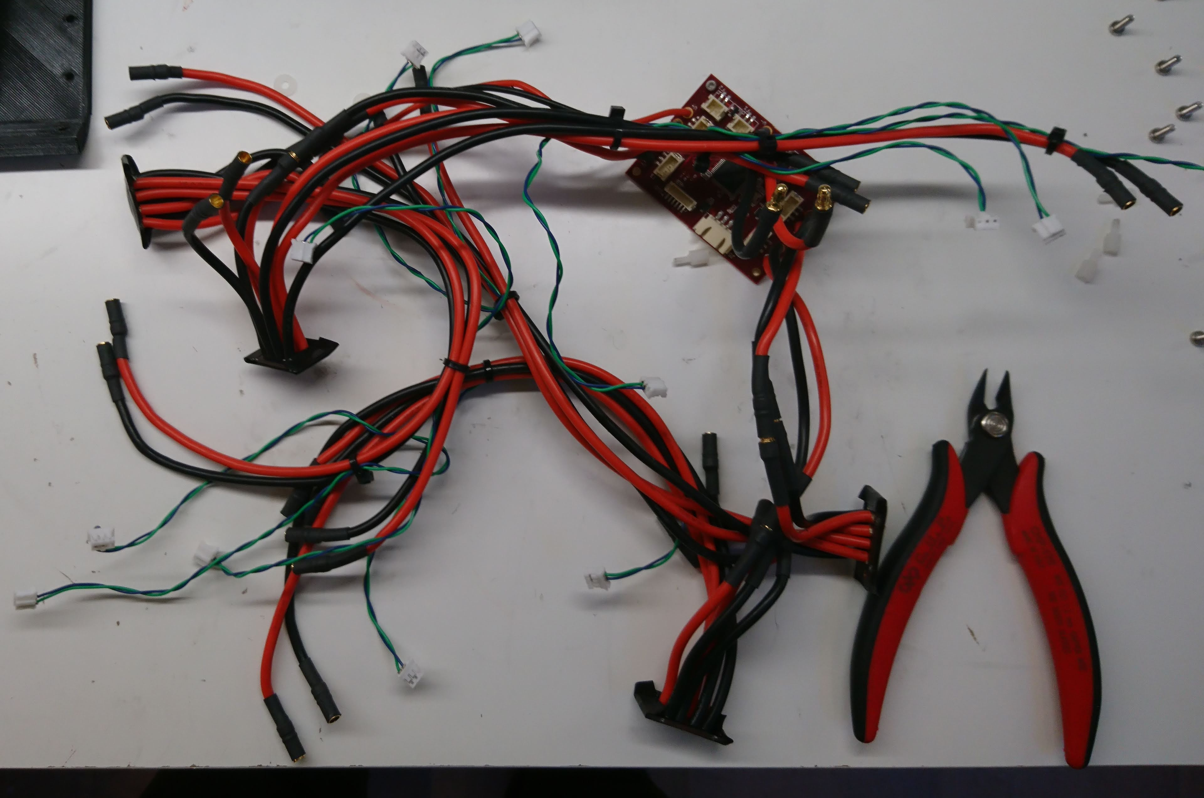
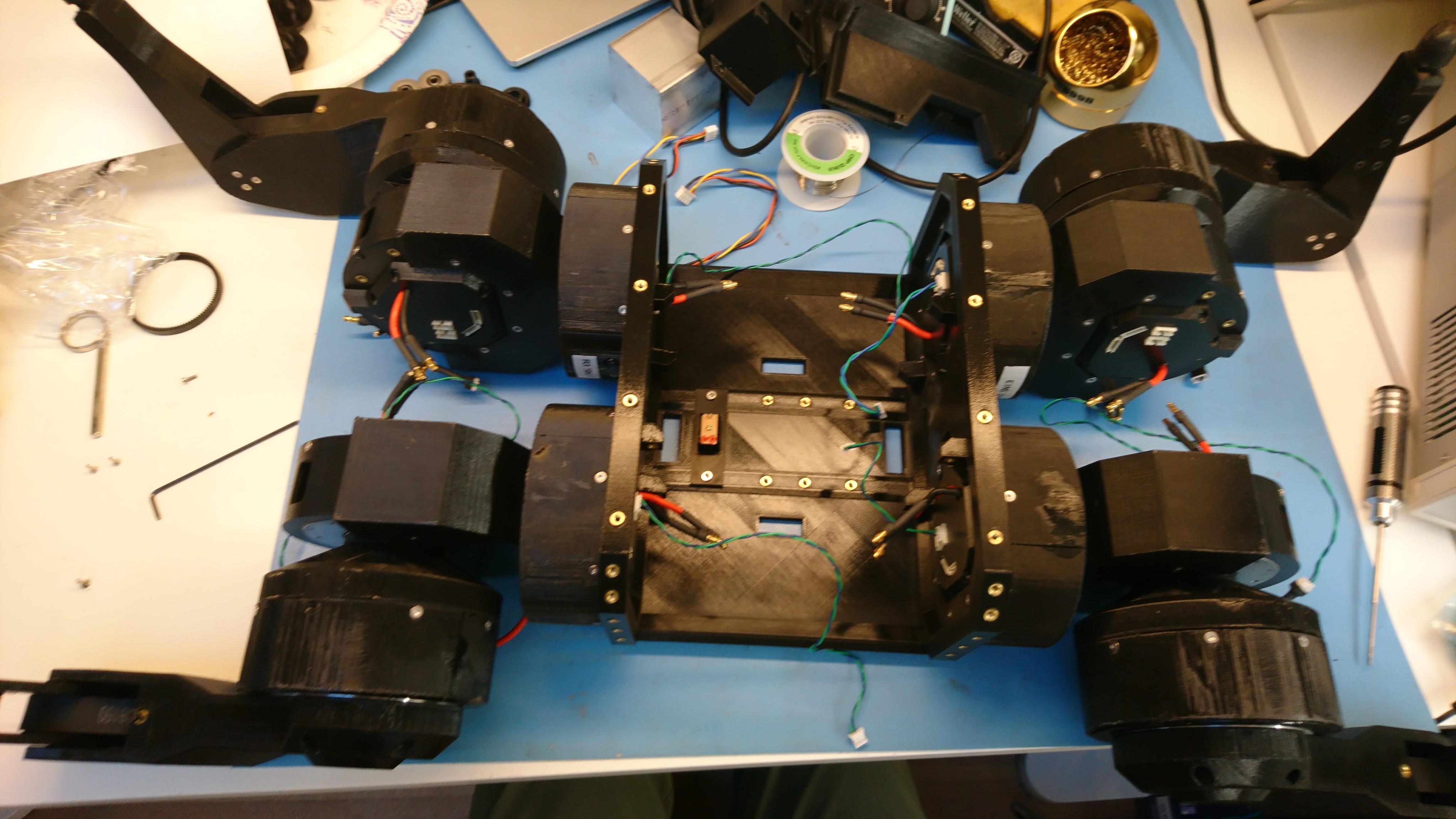
Now that I have a bunch of the mk2 servos set and ready to go, a new leg design, a new power distribution board to power them, and a raspberry pi3 hat to communicate with them, I built a new quadruped! I’m calling this the mjbots quad A1, since basically everything is upgraded.

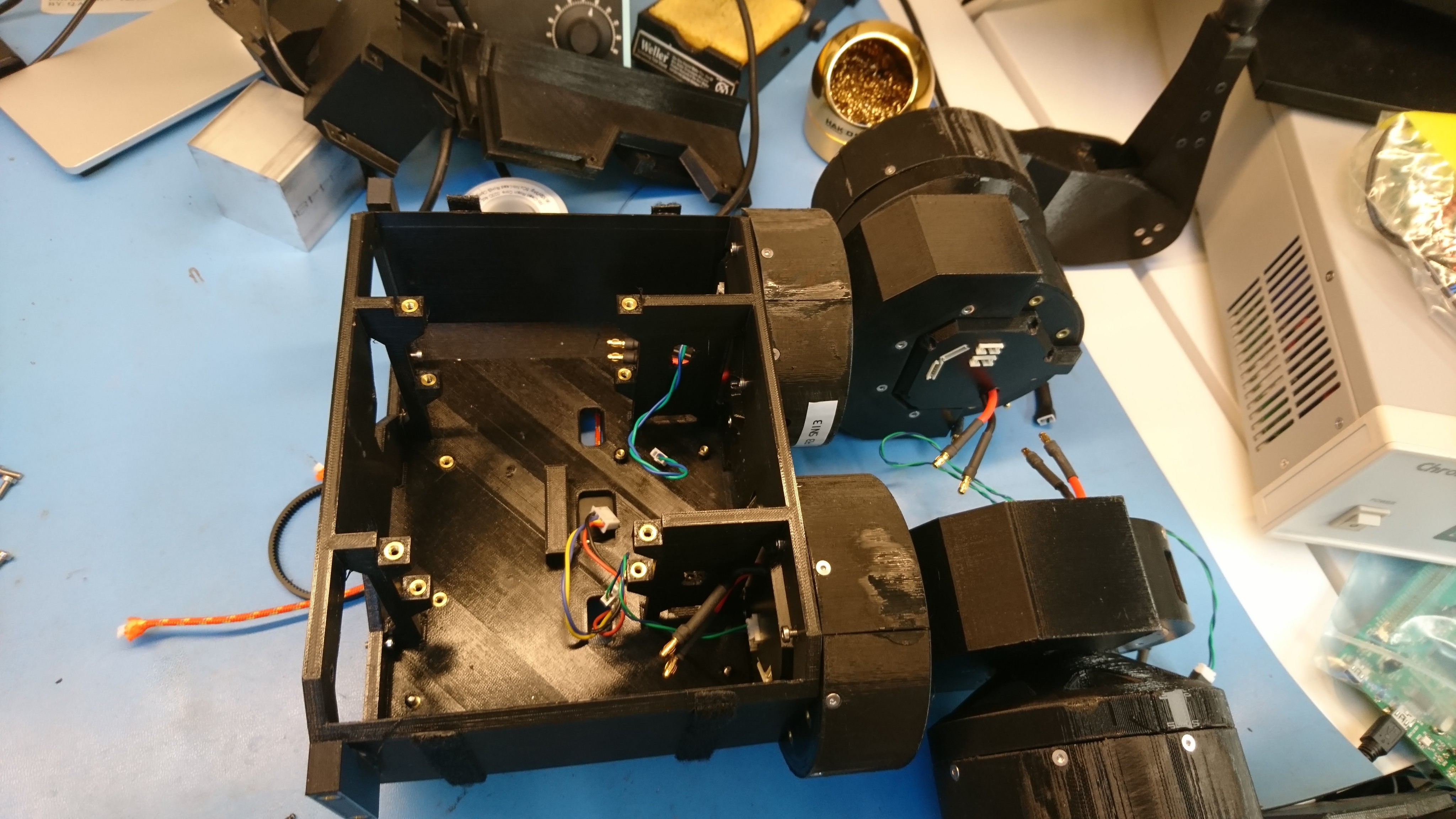
After I initially assembled the new legs onto the chassis, I realized I had the geometry slightly off and there was some interference through part of the shoulder rotation. I made up new printed parts and replaced everything in front of the camera. Thus, watch some high speed robot surgery:
The quad A1’s first job is to validate the new moteus controller in the quadrupedal configuration, after which I’ll use it as the primary development platform to get all my gait work done.