Yet another in the series on building a new leg for the quad A1:
Tag Archives: leg
A new leg for the quad A1 – Part 2
In the spirit of my last post on the topic, here is another video-only update on a new leg design for the quad A1:
Working on a new leg for the quad A1 – Part 1
I’m going to try something new for this effort, and instead of making a bunch of blog posts culminating in a video, I’m going to make a bunch of intermediate progress videos. They may, but may not, culminate in an overview blog post. Here’s the first!
Improved swing trajectory
Now that I finally have tplot2 working sufficiently to diagnose problems in 3D, it is time to start actually fixing those problems. The first obvious thing I noticed when watching data replay was that the legs scooted around a lot after making contact with the ground. Absent 3D visualization, I knew something was wrong, but couldn’t easily tell what.
Diagnosing the first problem
Once I was able to plot the commanded position and velocity trajectory, I could clearly see a number of problems. For one, the trajectory was not terribly achievable. The velocity jumped in a discontinuous manner between different phases of the swing cycle, which resulted in large tracking errors when moving the physical legs:

Also, there are those odd periods near the downturn where the commanded Z velocity goes to exactly zero for a while, then resumes its downward trend in a non-physical manner.
When I first wrote the simple walk cycle, I didn’t spend a whole lot (well almost zero) time debugging it, as I didn’t have appropriate debugging tools. Clearly it wasn’t working and something better needed to be done.
Updated swing trajectory
While not the entirety of the problem by any stretch, I figured fixing the swing trajectory was a fine first step that would be mostly independent of any other resolutions. I wanted the swing phase of the leg movement to have a few properties:
- Continuous velocity profile (I don’t care about jerk)
- When lifting off and touching down, maintain the ground velocity for a brief period of time
- For now, I’m not doing whole body control, so the trajectory can be scripted, and it is acceptable to lock in the target position at foot liftoff time
I decided to tackle the problem independently in the Z axis and in the XY plane. In both cases, the approach is based on piecewise cubic bezier curves. In one dimension, these curves have a continuous first and second derivative, but only the position and first derivative are controllable.
For the equation:

The position, velocity, and acceleration are as follows:

Z axis
To generate the Z trajectory, we’ll just stick two of these back to back in a mirrored fashion, so the Z height raises to a peak at the halfway point, then lowers back to the original value with a continuous velocity reaching exactly 0 velocity at the touch down point. That makes the overall Z trajectory look like:

X-Y Plane
In the X-Y plane, I broke up the swing into 3 piecewise sections. The first is a constant deceleration profile from the initial velocity to 0, and the last section is a constant acceleration profile from 0 to the target velocity. The middle section is just a single cubic bezier curve independently applied in the X and Y axes. A sample trajectory (with velocities shown as vectors), might look like:

Then to put the Z and X/Y pieces together, here’s a plot in the XZ plane of a similar system:

So yes, it seems to be doing what we want in that the velocity is continuous in all 3 axes — we lift off gradually, perform our swing, then set back down gradually.
Testing on the robot
Well, I actually tested it first in simulation, but where’s the excitement in that! Here’s what the tplot2 video looks like with the new leg trajectory in a slightly stuttery GIF:

The green and blue feet in the 3D view show that the legs track the control points well, and that 2D plots shows that yes, the Z position and velocity are smooth and continuous as we desired.
Quad feet construction fixture
The quad A1 was the first robot I built with foam cast feet. When I did the first feet, I jury rigged a fixture from some old toilet paper rolls to hold things in place while they were curing. When I went to rebuild with my most recent leg geometry, I figured it was time to get at least a little more serious. Thus, my new leg casting fixture:

When an insert is cast into place, it is set on one of the trays, the tray is inserted into a slot, and then a weight can be placed on top and constrained by the fixture.

This makes the casting process more repeatable and faster as I scale up production. As a bonus, it can also be used as a fixture to epoxy the lower leg to the insert:


Leg zeroing fixture
As part of provisioning a quad A1, or anytime the mechanical configuration has been changed, I need to go and record where the zero position of all the joints is. The “0” position for the software now is with the shoulders perfectly horizontal, and the upper and lower leg sticking straight down.
Up until now, every time I’ve done this it has just been by eyeballing and with lots of foam and bubble wrap to shim things into place long enough to record the level. Sometimes I had to go back and try a few times, as even determining when something is straight is not, well, straightforward.
So, I made two new fixtures to help with this process:

One that rests on a flat surface and supports the shoulder to be exactly level, and forces the upper leg to be exactly at a 90 degree angle. This assumes the robot is flipped over on the same flat surface. The second snaps between the upper and lower leg, forcing them to be exactly straight.
With these two fixtures, I was able to get repeatability of my calibrations down to less than half a degree, which should be good enough for now.

quad A1 leg updates
When I first designed the full rotation leg, I didn’t fully appreciate the importance of torque in the knee joint. Despite the fact that my first force based IK showed that when the legs are immediately under the body, the knee joint carries the entire load of the robot, I still managed to not add any reduction there.
The initial design used a 1:1 ratio, because that allowed me to use the same single piece 3d printed gear design I had used before. A 28 tooth gear with 5mm pitch resulted in a gear that was larger than the output plate on the qdd100 servo, so it could just be bolted directly on. To work with a smaller number of teeth, I had to split the gear into two parts, connected by pins, as the gear is now smaller than the qdd100 output plate.


So that I could use the same belts, I extended the upper leg about 8mm, and while I was at it, extended the lower leg by 15mm to make the overall leg a bit more symmetric.

We’ll see shortly how this works out when printed and assembled.

Final lower leg assembly
After casting the feet, the final step was to join the lower leg with the 3d printed foot bracket. This I just did with some slow cure epoxy.

It seems strong enough for now, I was able to manually apply 10kg of load to a single leg while perfectly horizontal with no signs of stress, which should be good enough for a 4g 4 legged jump.
All the legs (and a spare) are now assembled with belts and a lower pulley ready to go on a robot!


Casting feet
Previously, I described the overall plan for my improved foot. To make that work, I needed to cast a 3d printed part into the squash ball such that it would likely stay attached during operation, be suitable rigid and yet damped, and do so repeatably.
To start with, I used a random single yellow dot squash ball with a hole cut in one side using a pair of side cutters. For the casting foam, I just used Smooth-On Flex Foam-IT 17, which is what Ben Katz originally used at least. Initially I just mixed up a batch, poured it in to a random level, stuck my bracket in and hoped for the best.
Well, something sure happened! But not exactly what I wanted. The foam didn’t fill in the interior cavity, nor make a great connection overall with the bracket. On top of that, the process wouldn’t exactly be described as “repeatable”. Since I just eyeballed the level of foam, there was no way to get the same amount in.
For my next runs, I decided to do everything by weight. I tried a few different foam masses, curing orientations, and venting strategies. Eventually, I got something that seems to look pretty good. We’ll see how well it works on the actual machine shortly!
Here’s a bunch of different intermediate attempts:


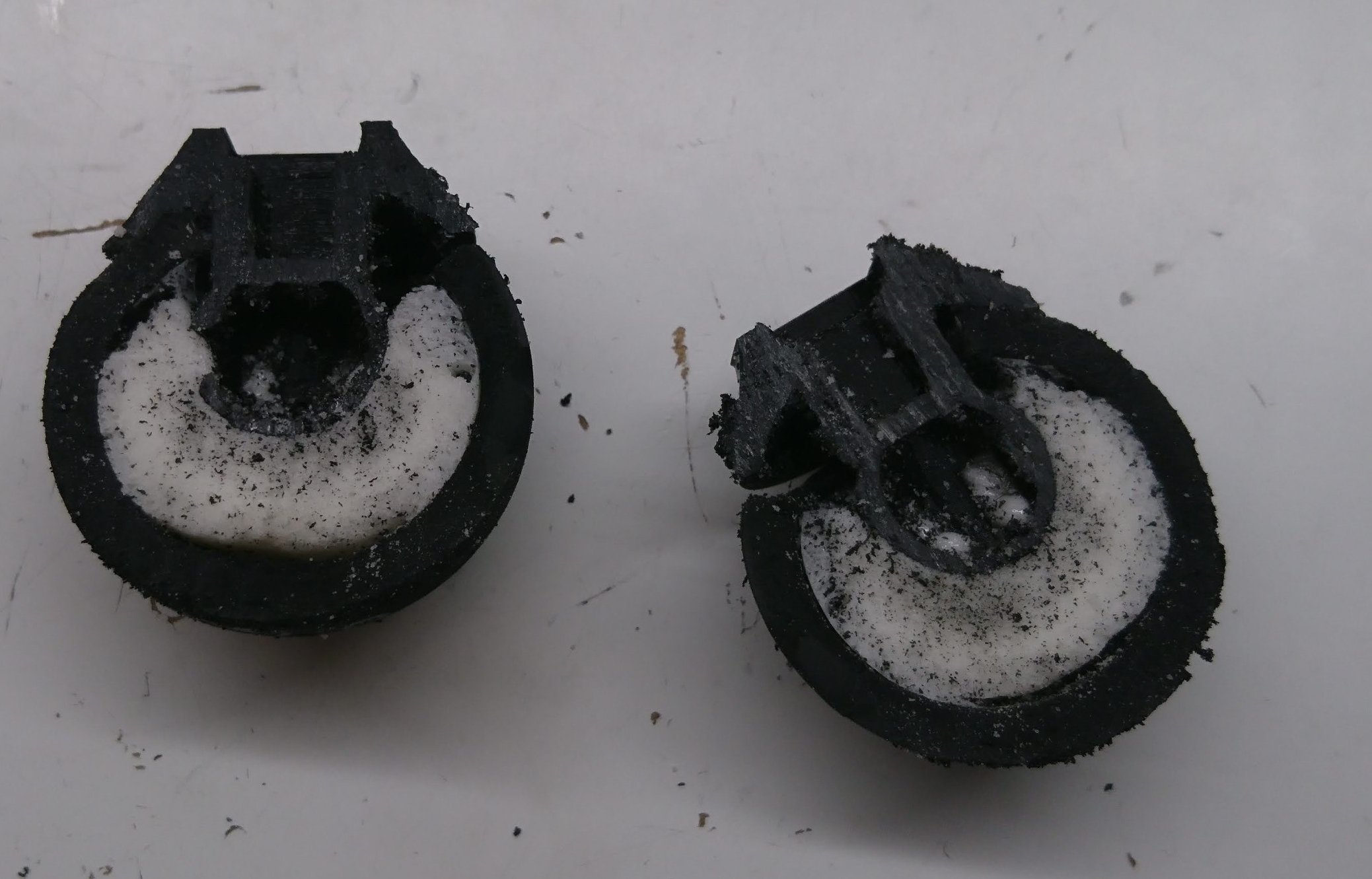
And here’s a cutaway of the process I’ve settled on for now. This particular one has a slight bit of overfill on one edge that is more than is typical, but the inside fill is pretty good:


quad A0 – Improved foot design
As mentioned long ago in my post on failing more gracefully, it was obvious I wanted to strengthen the lower leg and foot mechanism to remove the point of failure observed there. For now, I’m attempting to basically copy the original Mini-Cheetah foot principle, although with more 3d printing and less machining.

The basic idea is to print the entire lower leg in a single go laying on its side, so that delamination is unlikely. The foot bracket will be cast into a squash ball, then epoxied onto the lower leg.
Next up, we’ll see my experiments in casting!
