This is one of a series covering the new mjbots power_dist board. See part 1 and part 2 for more context.
As mentioned previously, hot swap controllers are primarily used to allow a card to be inserted live into a server backplane, while minimizing disruption to the primary power bus while doing so. Additionally, they often implement protection features like over-current and short-circuit protection, and some support energy monitoring.
Typical topology
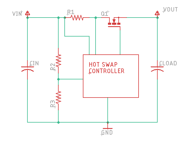
A typical hot-swap topology looks like:
Here, the high side FET is used for two purposes. During the “pre-charge” phase, the FET is operated in the linear regime, with a large voltage across it until the load capacitance is fully charged, at which point the FET reaches its “fully on” state and operates with its stated Rds on resistance. Notably, this means that the entire pre-charging energy is dissipated in those FETs, as opposed to the r3.1 design where a power resistor serves that purpose.
To accomplish the protection functionality, the current shunt (R1) is used to measure total current moving through the primary FET. Depending upon the particular chip, this could include over-current monitoring, where the FET is brought back into the linear operating region to limit the current, or short-circuit protection, where the FET is immediately turned off. Additionally, the resistor divider (R2/R3) can be used to program an undervoltage threshold.
Design constraints
The biggest challenge that a design faces with any hot swap controller is selection of the primary FET. Because it has to dissipate the entire pre-charge energy in a short time window, the device becomes very stressed. This limits the total capacitance that can be charged, the maximum voltage, and somewhat non-intuitively, the current that can be drawn during this startup window. For a design like the power_dist, where there is no “power good” signal distributed to downstream loads, they can draw what are effectively constant-power loads soon after the bus voltage reaches a valid intermediate state. Given that this can occur when there is still a large voltage across the high side FET, it can add a lot of energy dissipation.
To make this even harder, the design constraints are such that during the critical pre-charge window, FETs cannot be naively be placed in parallel. When operating in the linear regime, minute differences in device characteristics and temperature can cause drastic load imbalances. Thus controller design equations only allow parallel FETs for the purposes of increasing steady state on current, not increasing power or capacitance during the pre-charge window.
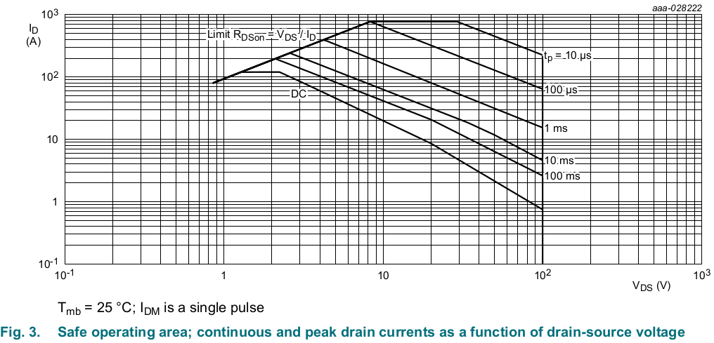
For a given FET, it will have a “safe operating area” plot like the below (this from the PSMN3R7-100BSE used in the soon-to-be-released power_dist r4):
This shows how much energy can be safety dissipated over different time windows. When designing the pre-charge system, it is then a balancing act of getting things to charge as quickly as possible, while not violating the SOA. Because of the details, going faster or slower can be problematic. Faster can be an issue because the energy may violate the short term peak energy, slower may be the culprit because the initial load current spends a longer time moving through the FET when it has a large voltage across it.
Next steps
In the next post, I’ll cover my various iterations, and where they fell short.
My initial design goals for this version are based largely around improving the major limitations identified before:
Positive side switching: By switching the positive rail, a whole class of use failures is removed, as most people expect ground to be common throughout a system.
Increased voltage range: moteus r4.5 and the pi3hat both support 44V, so any new power_dist board should support at least that.
Lower quiescent current: Ideally, the quiescent current would be measured in microamps, or at least at a level that it does not confuse BMS systems.
Energy monitoring: Often in the development of the quad A1, I wanted to have a system level power and energy monitoring solution so as to identify the energy cost of various maneuvers and gaits. Tracking that at the power_dist level seems like a logical place.
Wider load envelope: The 3.1 version had a relatively limited maximum downstream capacitance and turn-on current draw. It was enough to power on 12 moteus controllers and a small computer, but not much else.
To achieve these goals, I decided to try using what is known as a “hot swap controller”. These are integrated circuits that are intended for use in cards that plug into server backplanes. Given that any given card could potentially have a large decoupling capacitance, inserting it live into a backplane could cause arcing, and high currents that cause the overall bus voltage to drop outside of tolerable limits.
While such controllers are intended to be used at the point of load, they are largely applicable in this centralized system too, where the “hot plugging” is of a battery instead of an individual load.
And here is where my design story becomes “complicated”. Because both I didn’t fully work through the consequences of each design approach, and because I was not familiar with the intrinsic limitations of hot swap controllers, I ended up taking a route that involved 4 different prototypes before I arrived at one that was mostly acceptable. Rather than go down that route linearly, in the next post I’ll instead distill what I learned about hot swap controllers and design before describing the final solution.
The current iteration of the mjbots power_dist board released back in the summer of 2020 is pretty useful. It pre-charges the input, provides a soft switch, and gives you a bunch of output connectors to make wiring easier.
r3.1 Limitations
However, this version did have some limitations and potential problems. The first is that the pre-charge method it uses, a simple on/off pre-charge resistor, is unable to support a wide range of supply voltages. Either the resistor has a low value, in which case large input voltages will cause thermal failure, or for larger values, it isn’t able to actually pre-charge the bus sufficiently before engaging the primary MOSFET.
Secondly, it switches the negative rail. As pointed out in the documentation and by numerous YouTube commenters, if you are not careful, this can result in magic smoke being released if ground on the output and input is connected in any way.
Third, the protection afforded by the board is relatively limited. It merely performs the pre-charge function. It is still possible for short circuits or over-voltage events to result in damage to either downstream circuitry, or the upstream battery.
Fourth, the quiescent current is larger than I would like. At around 2-3 mA, it isn’t that large, but it means you can’t leave a battery connected for more than a day or so. Even worse, some BMS see that quiescent load as something they need to remain active for, which reduces standby battery life more substantially.
Looking forward
Given those shortcomings, I wanted to see if I could do better for the next revision. In the next several posts I’ll walk through my design process.
While testing some variants and new versions of the power_dist board, I wanted to be able to simulate the types of loads that it experiences with a fully loaded robot. Some things are easy, like this capacitor attached to an XT30 connector:
I also have giant power resistors in a similar form factor:
However, a dumb load resistor isn’t a particularly representative load. Most likely, the loads that a power_dist will drive are active loads with switching regulators. When the output voltage is lower, the current will be correspondingly higher. That is especially important when validating pre-charge behavior, because it means that the current is much higher during the initial pre-charge window than it would be for a pure resistive load.
Thus, I made a tiny switching regulator to which I can stick a load resistor to the output.
Unfortunately since MacroFab discontinued their prototype tier, it no longer is as convenient to get one offs populated in the US. So this one I did by hand with a stencil, solder paste, a 3D printed frame, and some new tools, a vacuum pick, and a hot plate. I discovered you can get room temperature stable solder paste now — how convenient!
There were a few bugs… I managed to not have 0603 resistors for the voltage sense divider on hand, but had 0402 of the right values so just stuck a blob of solder to connect them. On the same resistors, I also managed to get the PCB labels swapped. Fixing that resulted in a board that does what it is supposed to!
I’ve displayed versions of this numerous times in the past (May 2019, Feb 2020, March 2020), but now I’m proud to announce that I have a productized version of the power dist and precharge board available in the mjbots store for $79.
This board has convenient connectorization for powering sub-components of your robot, and also provides a smooth pre-charge sequence so that you can safely connect a large battery to high capacitance loads. I made a short video to show it off.
Another of the tasks I’ve set for myself with regards to future Mech Warfare competitions is redesigning the turret. The previous turret I built had some novel technical features, such as active inertial gimbal stabilization and automatic optical target tracking, however it had some problems too. The biggest one for my purposes now, was that it still used the old RS485 based protocol and not the new CAN-FD based one. Second, the turret had some dynamic stability and rigidity issues. The magazine consisted of an aluminum tube sticking out of the top which made the entire thing very top heavy. The 3d printed fork is the same I one I had made at Shapeways 5 years ago. It is amazingly flexible in the lateral direction, which results in a lot of undesired oscillation if the base platform isn’t perfectly stable. I’ve learned a lot about 3d printing and mechanical design in the meantime (but of course still have a seemingly infinite amount more to learn!) and think I can do better. Finally, cable management between the top and bottom was always challenging. You want to have a large range of motion, but keeping power and data flowing between the two rotating sections was never easy.
The legacy turret
My concept with this redesign is twofold, first make the turret be basically an entirely separate robot with no wires connecting it to the main robot and second, try to use as many of the components from the quad A1 as I could to demonstrate their, well, flexibility. Thus, this turret will have a separate battery, power distribution board, raspberry pi, pi3 hat, and a moteus controller for each axis of motion. These are certainly overkill, but hey, the quad A1 can carry a lot of weight.
The unique bits will be a standalone FPV camera, another camera attached to the raspberry PI for target tracking, a targeting laser, and the AEG mechanism, including a new board to manage the firing and loading functions.
The auxiliary CAN transceiver was switched to one that supports a larger common mode voltage. This will allow it to be connected to the power distribution board without smoking.
Each of the STM32s now has some GPIO pins connected directly to GPIOs on the raspberry PI primarily to be used for interrupts.
Pin headers expose a few gpio pins from each STM32 for interfacing with random external things.
The NRF radio module changed orientation and has improved power filtering.
I added a microphone to the auxiliary STM32. The goal is to eventually be able to use that to synchronize external video with onboard data collected during operation more easily.