Here’s the approximately annual giant video update:
If you’re interested in any of the topics in more detail, I’ve collected links to individual posts for each of the referenced items below.
Thanks for all your support in the last year!
Moteus
Announcement of moteus r4.3: Production moteus controllers are here!
Automated programming and test setup: Programming and testing moteus controllers
Dynamometer: Measuring torque ripple, Initial dynamometer assembly
Continuous rotation: Unlimited rotations for moteus
The virtual wall control mode: New “stay within” control mode for moteus
Handling magnetic saturation: Dealing with stator magnetic saturation
qdd100
Discussion of the overall design, and details on individual sub-components:
- moteus servo mk2
- moteus servo mk2: Planet Input
- moteus servo mk2: Outer housing
- moteus servo mk2: Front housing
- moteus servo mk2: Back housing
- moteus servo mk2: Functional test
- Making the reduced weight servo mk2
- moteus servo mk2: Reduced weight test
And the pre-production mk2 servos: Pre-production mk2 servos
Accessories
fdcanusb: Introduction and bringing it up
power_dist: The failed r2, the closer to working r3, and the final r3.1
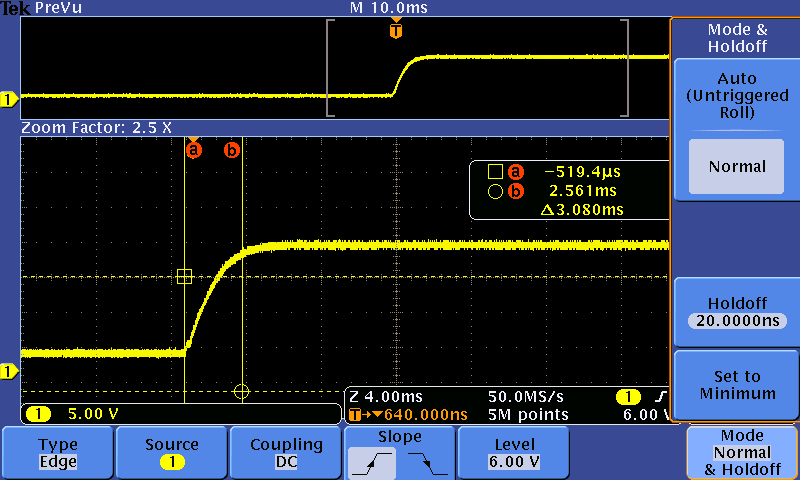
pi3hat: Initial announcement, bringing it up, and measuring its performance
Demonstrations
Ground truth torque testing: Ground truth torque testing for the qdd100
Skyentific’s telepresence clone: qdd100 telepresence demo
kp and kd tuning: Spring and damping constants
quad A1 – Hardware
Lower leg updates:
- The first quad A1 leg: Update leg design for mk2 servo
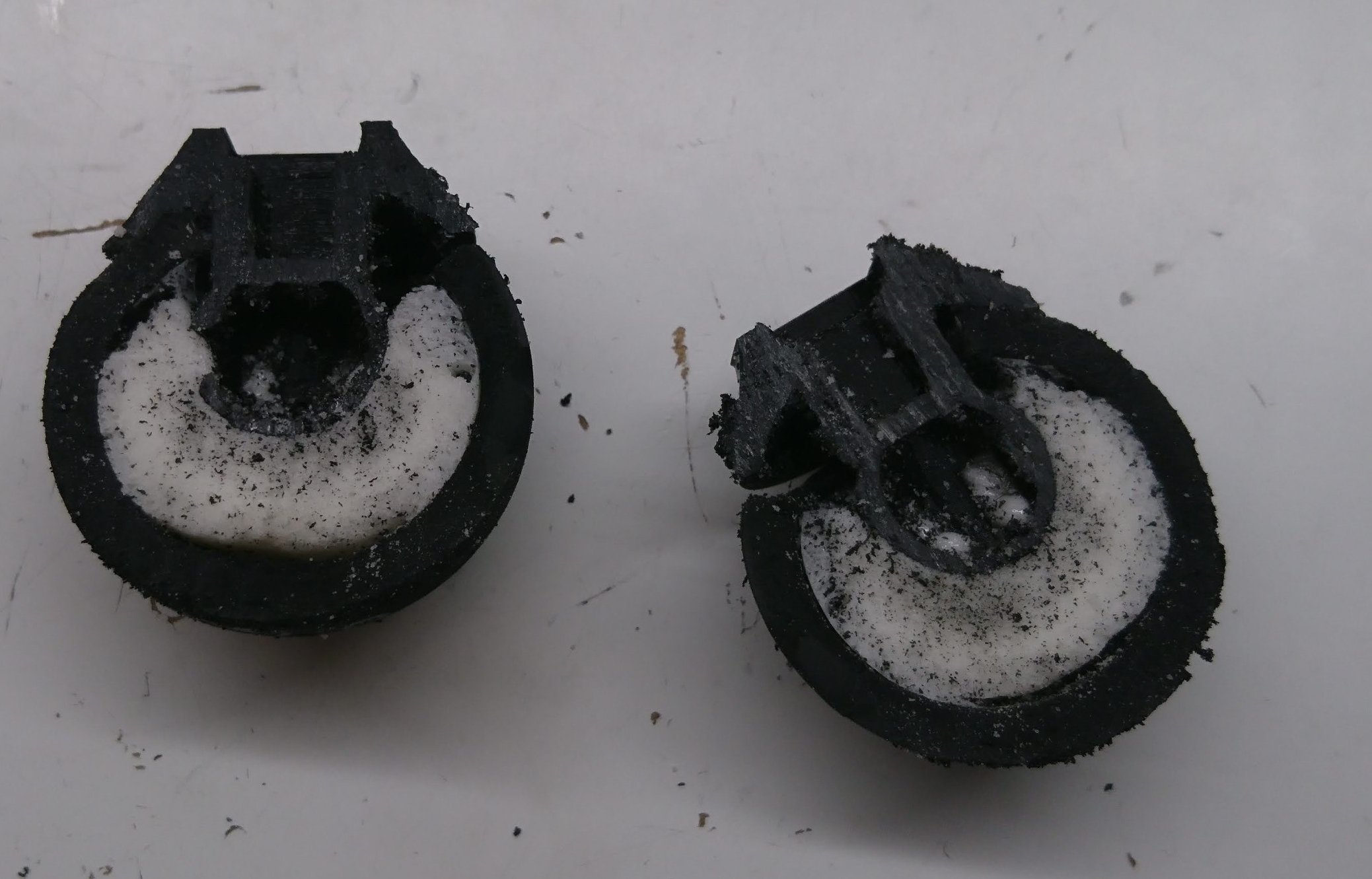
- The first foam cast foot: quad A0 – Improved foot design
- Longer and with a knee gear reduction: quad A1 leg updates
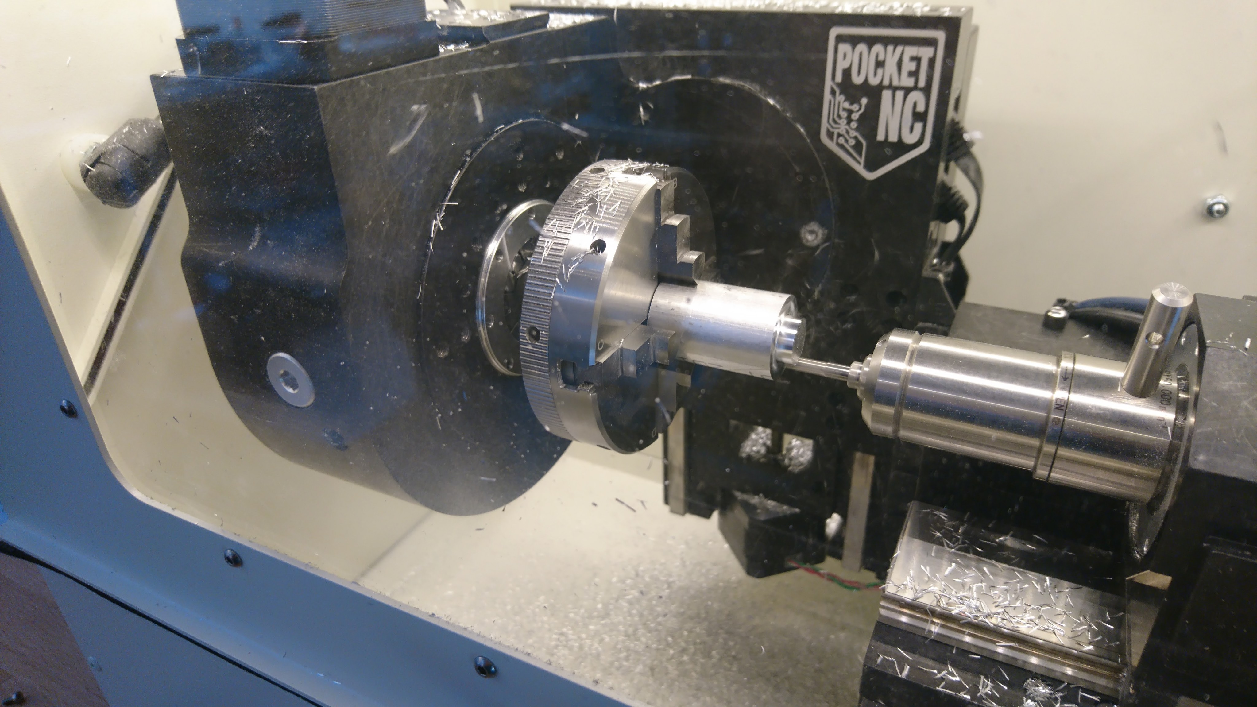
- A fixture to assemble legs: Quad feet construction fixture
- One of the feet failures: Another foot failure
Chassis: The first introduction, and some minor tweaks
Cable conduit changes: New leg cable management
quad A1 – Software
Cartesian coordinate control: Cartesian leg PD controller
Pronking: Successful pronking!
tplot2 and its sub-pieces:
- Updated serialization library
- Revised mjlib serialization design
- C++ serialization API
- Log file format
- tplot2
- Video in tplot2
- 3D rendering in tplot
- Video and telemetry synchronization
Simulation: Resurrected quadruped simulator
nrf24l01 transceiver and its sub-components
- Spread spectrum RF control and telemetry
- Spread spectrum protocol design
- Spread spectrum implementation
- Spread spectrum integration
Smooth leg motion: Improved swing trajectory
Balancing
- Primitive gait balancing – 1D
- Balancing gait in 2D
- Balancing on estimated terrain
- Testing real-life hill operation
All four feet off the ground: Higher speed gait formulation, and Stable gait sequencing
Improved stand up sequence: quad A1 stand-up sequence part N
Speed records:
- 0.5 m/s: Balancing gait in 2D
- 1.7 m/s: First look at higher speed gaits
- 2.0 m/s: Another speed record: 2 m/s
- 2.5 m/s: Another quad A1 speed record – 2.5 m/s