Tag Archives: moteus_r4

More MLCC learning

It seems that I’m learning much about PCB design the very hard way.  Back last year I wrote up my discovery of MLCC bias derating.  Now I’ll share some of my experiences with MLCC cracking on the first production moteus controllers.

When I was first putting the production moteus controllers through their test and programming sequence, I observed a failure mode that I had yet to have observe in my career (which admittedly doesn’t include much board manufacturing).  When applying voltage, I got a spark and puff of magic smoke from near one of the DC link capacitors on the left hand side.  In the first batch of 40 I programmed, a full 20% failed in this way, some at 24V, and a few more at a 38V test.  I initially thought the problem might have been an etching issue resulting in voltage breakdown between a via and an internal ground plane, but after examining the results under the microscope and conferring with MacroFab determined the most likely cause was cracking of the MLCCs during PCB depanelization.

dsc_0415
A very obviously cracked capacitor

Here’s a video describing the problem and potential solutions in way more detail than I’ll go into:

Needless to say, I hadn’t managed to see this failure in the 100 or so previous moteus controllers I’ve built, or I would have figured this out and resolved it!

For this first round of production controllers, I went and replaced every single capacitor near the edge of the board with a TDK variant that has internal soft termination, then tested them all at max voltage and a little beyond.  Future revisions will use that variant of capacitor everywhere, as well as relocating the capacitors to reduce the mechanical stress they experience during manufacturing, handling, and installation.

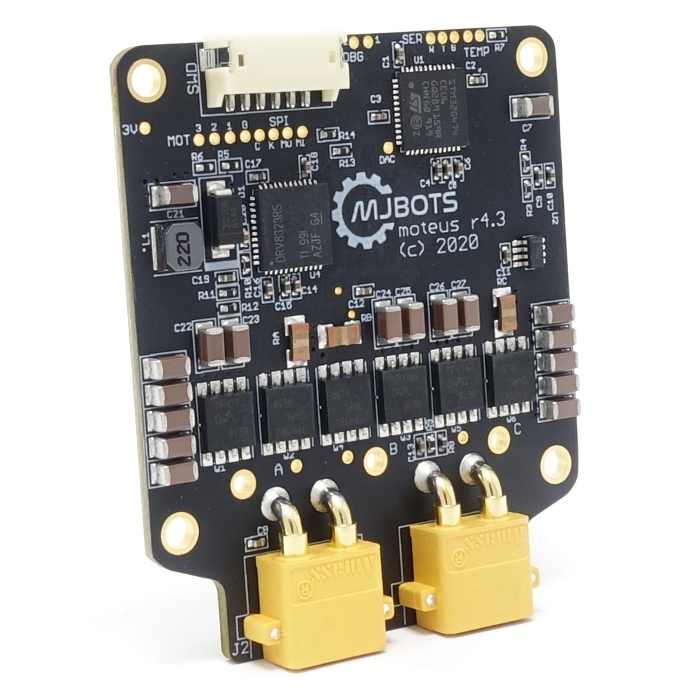
Production moteus controllers are here!

Developing the moteus brushless servo controller has been a very long journey, and while it isn’t over yet I have a reached a significant milestone.  The first batch of production moteus controllers are now available for general purchase at mjbots.com and shipment worldwide for $119 USD each!

moteus_r43_front_left

I’ll repeat some of the specifications here:

  • 3 phase brushless FOC control
  • 170 MHz 32bit STM32G4 microprocessor
  • Voltage: 12-34V
  • Peak phase current: 60A
  • Dimensions: 46x53mm – CAD drawing in github
  • Mass: 14.2g
  • Communications: 5Mbps CAN-FD
  • Control rate: 40kHz
  • Open source firmware: https://github.com/mjbots/moteus

Simultaneously, I’ve got development kits available that give you everything you need to start developing software for the moteus controller out of the box: moteus r4.3 developer kit

moteus_r4_3_devkit_back_left

Many thanks for all the feedback from the beta testers who have been experimenting with the r4.2 version!

CAN bootloader for moteus r4.x

One final piece of porting that needed to happen for the moteus controller r4.x series was the bootloader.  The r3.x series has a bootloader, which allowed re-flashing the device over the normal data link, but that was largely specific to the RS485 and mjlib/multiplex framing format.  Thus, while not particularly challenging, I needed to update it for the FD-CAN interface used on the r4.x board.

The update itself was straightforward: https://github.com/mjbots/moteus/compare/406f01…1123a9

For now, on the assumption I will in the not too distant future deprecate the r3.x series, just duplicated the entire bootloader, replacing all the communication bits with FDCAN and stm32g4 appropriate pieces.  As before, this bootloader is designed to only operate after the normal firmware has initialized the device, and also is required to be completely standalone.  To make code size easier to manage, it makes no calls to any ST HAL library and manipulates everything it needs purely through the register definitions.

Thankfully, the ST HAL sources are BSD licensed, otherwise I’m not sure I could have gotten the FD-CAN and flash peripherals to work just given the reference manual.  With it, copying out the necessary constants made for an easy solution.


Moteus controller devkit PCBs in house

Update 2020-01-15: All the development kit slots are full.  Thanks for your interest!

I’ve now received all the supplies I need to make up development kits for the moteus controller and to make a test quadruped!

I’m planning on making a few development kits from this production run so others can experiment with the moteus brushless controllers.  Some people have already expressed interest in getting one — you have hopefully been contacted earlier.  If you are interested in getting an opportunity to buy an early access kit and haven’t heard from me yet, fill out this form!

I expect the development kits to clock in at $199, and include everything you need to power and communicate with the moteus controller, as well as a brushless motor to test with.

dsc_0133
Some fdcanusb boards
dsc_0150
The moteus controller r4.2
DSC00164.JPG
An in-progress moteus development kit
dsc_0149
Lots of moteus controllers!


Endurance testing moteus controller r4.1

Before ordering a bigger batch of the new moteus r4.1 controller, I wanted some assurance that it would be able to run for an extended periods of time under representative loads while not breaking or having thermal issues.

dsc_2095
r4.1 mounted up

When I did this for the r3.1 controller, I had 2 motor joints and a planar leg built and did a jumping endurance test.  I could have done that now, but building up a leg fixture was more work than I wanted to mess with at the moment, so I went with a simpler approach:

dsc_2074
Getting ready…

I joined two of my fun past-times, robots and juggling!  I printed up an arm with a pocket, stuck a 1lb (450g) juggling ball in it, and set the thing throwing.  Mind you, this is probably one of the worst juggling robots in existence, I only built it to stress test the motor controller.  I’ve had it throwing the ball now for several hours at 4Nm without dropping, here’s a video of some of the testing.


moteus controller r4.1

Another step in my plan for the next revision of the moteus servo mk2, is an updated controller board.  As mentioned in my roadmap, I wanted to revise this board to make improvements in a number of domains:

  • Communications: Now instead of RS485, the primary communications interface is FD-CAN.  This supports data rates of up to 8 Mbit and packet lengths up to 64 bytes.  The header is nominally at the original CAN bit rate, but I have no need to be standards compliant and am running very short busses so I may run everything at the higher rate.
  • Connectors: Now there exist power connectors, in the form of XT30 right angle connectors and they are also daisy chainable like the data connectors.  Additionally, all the connectors exit from the bottom of the board to make routing easier in configurations like the full rotation leg.
  • Controller: This uses the relatively new STM32G4 controller series.  It is lower power than the STM32F4, supports FD-CAN, and also supports closely coupled memory, which may allow me to improve the speed of the primary control loop execution by 3 times.
  • Voltage range: This board now has 40V main FETS, with all other components at 50V rating or higher.  Thus it should be safe with inputs up to 8S (34V or so).
moteus_r41
moteus r4.1 rendering

It still maintains a number of the capabilities of the moteus r3.1 controller:

  • Integrated FOC encoder: An AS5048 encoder is mounted in the center of the back, which allows direct mounting above the rotor for FOC control.
  • Form factor: The entire board is 45x54mm, with M2.5 mounting holes.  It is smaller than a 60mm BLDC motor and much smaller than an 80mm one.
  • Integrated current sensing: It uses a DRV8323 to drive the FETS, which includes current sensing for closed loop current control.

My first attempt at this, “r4”, came back from fabrication in an nonredeemable state.  I used the digikey supplied footprint for the STM32G4 UQFN part, which looked mostly correct on the surface.  However, while the footprint was good, the pinout was for the TQFP variant!  This resulted in me shorting out several power pins to ground right next to the exposed pad in a way I couldn’t easily rework.

r4.1 seems to be in better shape so far.  It powers up, and I now have blinking lights!

dsc_1958
moteus r4.1 as built

Next up is actually porting the control software to the new controller and communications interface.