Tag Archives: moteus_r48

Velocity and acceleration limited trajectories

One of the oldest requested features for the moteus brushless controller has been a form of trajectory control beyond constant velocity trajectories. For most applications this is not an actual deal-breaker, because arbitrary trajectories can be approximated by piecewise linear constant velocity trajectories in the application layer. However, for many people, that is big hurdle to jump over to start with, and for some, it can actually limit application effectiveness because a fair amount of CAN bandwidth is required to achieve the high rate control necessary for smooth motion.

So, as of release 2022-04-07, moteus now supports velocity and acceleration limited trajectories out of the box. All devkits now come with human-eye-pleasing limits enabled by default, although bare boards leave it disabled as per board defaults. There are two parameters to control the feature:

  • servo.velocity_limit – The maximum velocity used when moving to a particular target goal
  • servo.acceleration_limit – The maximum acceleration used when moving to a particular target goal

Additionally, these limits can be overridden on a per-command basis, both using the diagnostic protocol “d pos” mechanism, and the register implementation.

Check out this video, then read below the fold for more details:

There are a few details to the implementation which help it fit better into the existing moteus control framework, while enabling some features that don’t exist elsewhere.

Special-valued limits

First, either limit may be “nan”, (the usual special value in moteus configuration-speak). In that case, no limits are applied. If both are “nan”, that results in identical behavior to what was previously used in moteus, in that a “d pos” command immediate attempts to achieve the desired position and velocity. If velocity is limited, but not acceleration, all such commands result in constant velocity trajectories to reach the target position, followed by continuing at the target velocity indefinitely. If acceleration is limited but not velocity, then the velocity will be continuous, but unbounded (except possibly by servo.max_velocity). If both are limited, then the velocity will be continuous and bounded.

Non-zero velocity targets

The target state is a position and a velocity. moteus will reach the position and be traveling at the desired velocity when it reaches it. After reaching the state, the controller will continue at that target velocity indefinitely, or until another command is received.

Idempotent commands

For many cases, it is still possible to construct commands such that they are idempotent. That means that you can send the same command over and over and it will not affect the semantics of the control. This is particularly easy if the destination state has a zero target velocity.

If the destination state has a non-zero velocity, then the command will need to change sufficiently far in advance to avoid “looping around”. If a command with a non-zero velocity is received after the machine has passed through the target state, then the only way to achieve it is to slow down, go back, and accelerate again so as to be moving at the proper speed. For applications like these, it is best to always have the target be at least several control cycles in the future so there is no risk of such looping.

Completion indication

It is now feasible, in many cases, to send moteus control commands very infrequently. A complete motion from stopped in one position to stopped in another can be initiated with a single command. So that the application code can advance in a timely manner, moteus now reports a “completion” indication that flags when the target position and velocity has been reached. This can be accessed as register 0x00b in register mode, or as servo_stats.trajectory_done in diagnostics mode.

Interaction with the “stop position”

Previously moteus had the “stop position” mechanism to emulate a constant velocity trajectory with a fixed endpoint. That mechanism is still present. While it has defined interactions with the acceleration and velocity limits, they are, shall we say, “not particularly useful”. Thus, it is recommended to not use the “stop position” feature combined with the velocity and acceleration limits unless you really know what you are doing.

Jerk limited trajectories

The implementation in moteus only supports limiting acceleration, not jerk. Thus the acceleration is allowed to be discontinuous. For an application where jerk limited trajectories are required, piecewise interpolation is still required. For accelerating phases, this can be trivially accomplished by slewing the acceleration limit override in each moteus command. For decelerating phases, or where precise control over position is required, a full fledged jerk-limited planner (like ruckig) will be required. The output from such a planner is probably easiest to feed to moteus as a piecewise series of constant velocity trajectories with no limits configured as before.

customizable PWM rate for moteus

Being a switch mode 3 phase motor driver, the moteus controller changes the current flowing through the phases of a motor by rapidly switching the phase terminals between the positive input voltage and the input ground. The control of this switching is denoted “pulse width modulation”, or PWM for short. To date, the rate at which it has switched has been fixed in firmware at 40kHz. As of release 2022-03-12, this can now be altered anywhere between 15kHz and 60kHz to better optimize peak power capability, control bandwidth, maximum speed, and heat generation.

Read on for more details:

Peak power

Switch mode motor controllers typically have large banks of capacitors across the input immediately next to the active switching elements. This bulk capacitance has the primary goal of minimizing voltage ripple during switching events. When a switch is engaged to apply more current into the motor, that energy is pulled from the capacitors, and when a switch is engaged that pulls energy back out, that energy is stored back into the capacitors. Only more slowly is the energy pulled to and from the primary input terminal. The magnitude of the ripple is determined by the effective capacitance, the power applied to the motor, and the switching frequency. More capacitance decreases the ripple, more power increases it, and higher frequencies decrease it, all in roughly linear relationships.

For moteus r4.5 and r4.8 (and likely subsequent revisions of this design), this voltage ripple is what controls the peak power that moteus can drive. moteus is designed to have a very small form factor, and thus uses only MLCC capacitors for its bulk DC decoupling. This results in it having an abnormally small bulk capacitance compared to otherwise similar controllers (doubly so because of MLCC capacitor derating).

The rated 500W of peak power for moteus (limited to 450W by default in config), can be achieved with the default 40kHz switching rate. By increasing the switching rate, the peak power can be increased to 750W, and if the switching rate is decreased to the minimum of 15kHz, then the rated peak power is around 190W.

Heat dissipation

Switch mode controllers generate heat while operating as a result of many factors. The two biggest ones for moteus can be broken down into “dynamic” and “static” components of the gate drive and switch MOSFETs.

The easiest to understand is the “static” component of the switching losses. When the power MOSFETs are fully turned on, the power dissipated in them is determined by their on resistance and the amount of current, using the formula P=I^2*R. The on resistance for MOSFETs generally increases with temperature, so the worst case will be at the maximum rated temperature of the device.

The dynamic component encompasses a few different pieces. One, is that while the MOSFETs are in the process of turning on and off, their resistance is much higher than when fully on. Another is that during the “dead-time” window between when the high side and low side of the H-Bridge is enabled and neither is actively driven, the current is conducted through the body diode of one of the MOSFETs, which has what can be modeled as a fixed voltage drop. The third big component of this is the energy required to charge and discharge the gate capacitors of the primary switching MOSFETs. The energy used in the dynamic region for a given power output stays roughly constant for each switching event. Thus switching faster results in more energy used per unit time scaling in a roughly linear manner.

Further, the dynamic component significantly depends upon the input voltage. Higher input voltages mean that the MOSFETs take longer to switch for a given gate drive current, that the power dissipated is larger during the switching events, and that more energy is required to charge and discharge the gate capacitors.

Thus as the switching frequency increases, the power used consumed during the switching events goes up, while the total time spent in the static region goes down. That means the efficiency goes down as the switching frequency goes up.

Control bandwidth and motor speed

For PWM rates of 40kHz or less, moteus implements its entire control loop at the PWM update rate. When this control rate is decreased, the bandwidth available for control of torque, and subsequently position decreases.

Also, the maximum electrical RPM that the controller can achieve is also directly related ot the control rate. However, few applications reach the 1.5kHz electrical frequency possible at 15kHz, so this is not often a concern.

Due to the implementation details, selecting PWM rates above 40kHz results in the control cycle running every other switching event. That means that the maximum control bandwidth and electrical speed is achieved for a pwm rate of exactly 40kHz. Higher or lower and those bandwidths and speeds are decreased.

Thermal experiments

To show the effects of changing the PWM rate on thermal performance, I made up a simple experiment with a moteus r4.8 and an mj5208 attached to a devkit bracket but disconnected from the moteus so that they would be thermally decoupled.

The fixed voltage mode was used to slowly spin the motor while progressively larger amounts of current were applied to the motor. This approximates operating with full torque at a standstill, where the motor performs almost no mechanical work. For each current, I waited for the temperature in the motor windings and the controller to stabilize.

Using this data, I was able to roughly estimate a few parameters at these different operating points. First, in ambient air with no heat sinking or forced cooling the mj5208’s thermal conductivity is around 4 C/W. moteus’s thermal conductivity in the same environment is around 40 C/W. The thermal efficiency and effective idle thermal generation of the controller at various operating points can be seen below along with the available peak power:

PWM FrequencyPeak Power24V36V
15kHz190W94% / 0.20W92% / 0.25W
40kHz500W88% / 0.25W85% / 0.30W
50kHz625W84% / 0.30W84% / 0.35W
Thermal efficiency for moteus r4.8 driving a nearly-stationary motor

These efficiency tables can be used to roughly determine the thermal design for moteus in a setting with air cooling, no heat sink, and any motor heating dealt with independently. If you are running the default 40kHz PWM rate at 24V and are applying 5W of power to your motor, that means the total power consumed will be 5W/0.88% +0.25W=5.93W. The 0.93W of waste power dissipated in moteus will result in its temperature being approximately 0.93W* 40C/W=37C higher than ambient.

That value can be improved either by lowering the PWM frequency or input voltage to improve efficiency, or by using heatsinking and/or forced air or liquid cooling to decrease the effective thermal conductivity of the controller.

How to configure moteus

Once you know the PWM frequency you want to use, selecting it is as simple as setting the servo.pwm_rate_hz configuration value to something between 15000 and 60000.

It is important to note that the maximum power configurable value, servo.max_power_W is now defined as the power when configured at 40kHz. Internally it is scaled accordingly if the PWM rate is changed. This means you can change the PWM rate without worrying about accidentally having too large of a power limit configured.

external primary encoders for moteus

With the r4.8 release of moteus, a not-yet-announced feature was included — the ability to have an off-board primary encoder! It didn’t get announced at the time, because the connectors necessary to populate the board were not obtainable. In fact, that is still the case, but I’ve located a substitute part which works well enough, so here we go!

Theory

The moteus controller uses an absolute magnetic encoder to determine the relationship between the rotor and stator of the motor at each given instant. That allows it to produce torque in the motor at any speed, from standstill to the maximum possible speed. Until now, the only magnetic encoder that was supported is the one mounted to the backside of the board. This is largely acceptable, as moteus is intended to be used in integrated applications.

However, some users like the moteus form factor and capabilities, but don’t have room to put the entire board right next to the sense magnet. Now the pads on the back can be used for just that:

These pads contain SPI signals that can be optionally configured to enable an external primary encoder. As of now, the only encoder IC supported is the same one that is mounted on the board, the AS5047P (or anything with an identical SPI protocol).

Usage

To use this mode, you need to connect the external AS5047P IC to the pads on the back of moteus. You can do that with either connectors, or by soldering bare wires to the pads. The following connector set is in stock at Digi-Key as of 2022-03-07 and is compatible:

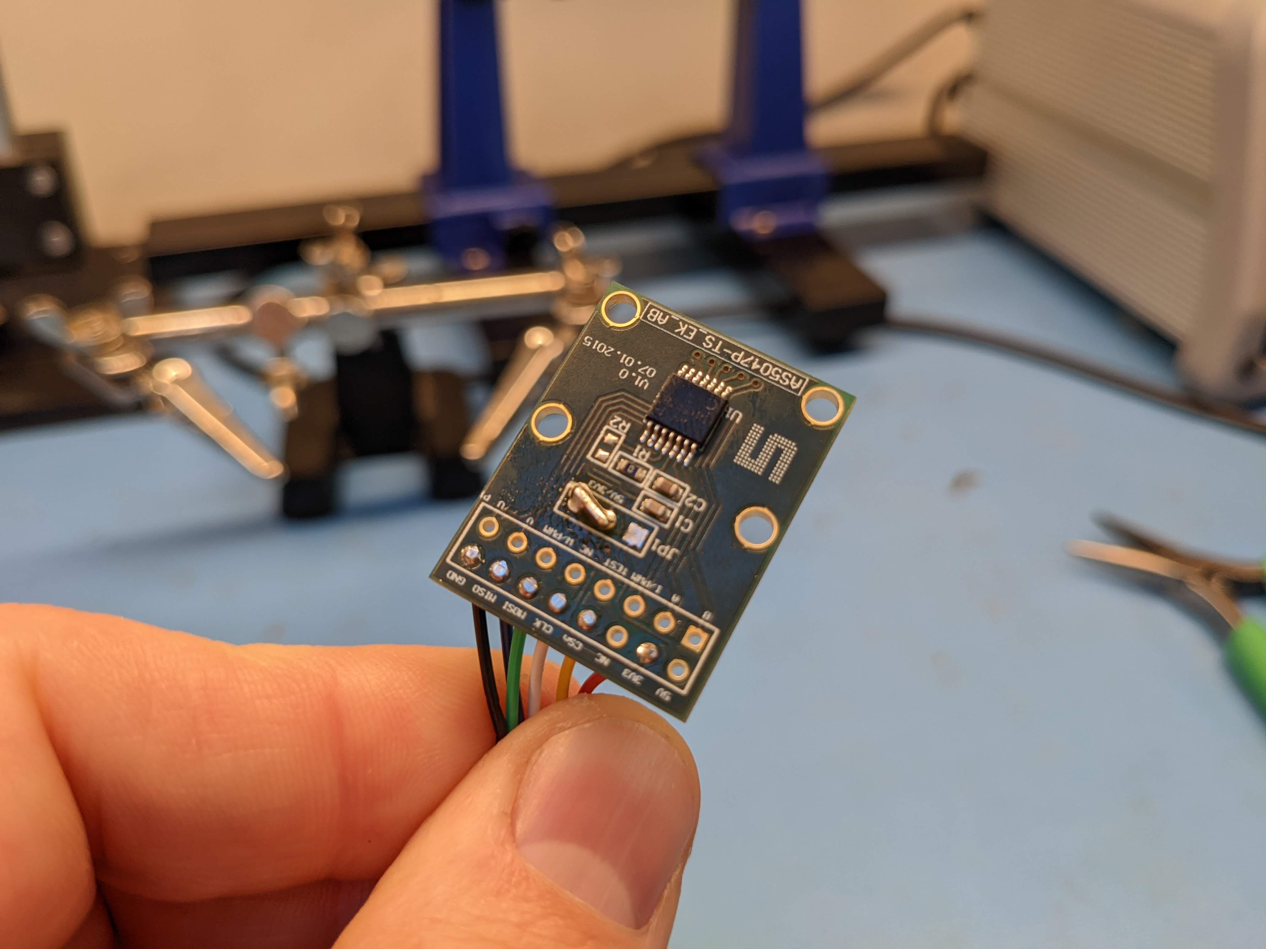
Additionally, Digi-Key stocks a breakout board for the AS5047P, with which slight modification can be used:

To use this, you need to position the jumper to connect the 3.3V supply as the primary source. In my example here, I pulled out the pins and soldered a bridge across it so it could fit flush against a motor.

AS5047P breakout configured for 3.3V

Finally, you need to enable the external encoder in configuration:

  • encoder.mode – Set to 1 for an external AS5047 SPI compatible encoder

At this point, the motor can be calibrated as usual.

Limitations

As moteus uses a high bit-rate for SPI (12Mhz), the allowable connection length is short, <20cm is recommended. The wires will be somewhat sensitive to interference, so the allowable length may be even shorter for environments with large amounts of EMI.

While encoders other than the AS5047 may be supported in the future, the possibilities are somewhat limited due to the way moteus samples the encoder currently.

Video

Here’s a video showing all this put together:

Fixed voltage mode for moteus

The most recent moteus firmware release, 2021-12-03, added not one, but two new control modes for less common applications. Previously, mentioned was the “voltage_control_mode” for using gimbal style high resistance motors without changing the sense resistors. In this post, I’ll describe a similarly named, but very different mode “fixed voltage mode” for operating brushless motors as if they were a stepper motor.

For some applications, you don’t care about torque control, or about power consumption at all. Traditionally you would use a stepper motor in those applications, with a correspondingly less expensive stepper motor driver. However, in some cases you may still want to have high rate trajectory control, CAN based telemetry, or have already standardized on moteus controllers for other moving parts of your solution. There are two new options that can be used in such situations:

  • servo.fixed_voltage_mode: When this is non-zero, the primary encoder is not used for control at all. Instead, positioning is performed entirely in the electrical phase space, with a fixed voltage applied always to the phase windings.
  • servo.fixed_voltage_control_V: The fixed voltage to apply to the phase windings.

When this new mode is active, the controller will continually burn power in the windings of the motor and uses no feedback from the motor at all. As mentioned above, this makes it operate like a micro-stepping stepper motor, or an inexpensive gimbal motor controller. If the externally applied torque is greater than that produced by the fixed voltage, the motor will “skip” and lose track of its position.

Voltage mode control for gimbal motors

The moteus brushless controller can drive many motors out of the box, but until now it has been challenging to use with gimbal style brushless motors. They are wound with thin wire so that they have a very high winding resistance, and thus can be driven by inexpensive low current controllers. Using something like moteus with a gimbal motor isn’t absolutely necessary, but does give benefits in terms of high performance trajectory tracking and torque control.

The problem

The primary challenge when using moteus with high winding resistance motors is the mechanism moteus uses to sense current through the motor phases. It has a set of 3 current sense shunts, basically resistors, that have a small voltage induced across them proportional to the amount of current flowing. When commanding a specific current, moteus continually adjusts the voltage on each of the phase windings until the desired current is achieved. These resistors are sized so that moteus has reasonable resolution up to its 100A maximum current rating. When used with a motor that has a maximum current of 1A though, almost all of this resolution is wasted.

In the past I have replaced the sense resistors on moteus boards in order to drive gimbal motors. That is the optimal solution, as it allows moteus to continue to sense the current through the windings and provide accurate torque control. But not everyone is set up to perform surface mount soldering, and accurate torque control at all speeds and temperatures is not required in many applications.

Voltage mode control

As of release 2021-12-03, moteus now has a new configurable option, called “voltage_mode_control”. In this mode, torque commands no longer use the current sense resistors for feedback. Instead, they use the calibrated phase resistance of the motor to derive what voltage would be necessary to achieve a given torque.

The downsides of this approach are that there are many factors that will make the mechanical output torque not match what was intended. For instance, the back EMF if the motor is moving at non-zero velocity, changes in the winding resistance due to temperature, or inductive coupling between the quadrature frames at non-zero velocity. All of these factors will reduce the accuracy of the torque command, so that the mechanical torque output will not match what was commanded. However, for many applications, the motor is not spinning quickly and precise torque control is not required.

Since this control mode takes effect only at the end of the normal moteus control loop, it means that all of the “position” mode control works as before. Thus the constant velocity mode, stop position, and the “within” mode can all be used without regard to whether the controlled motor is running in the normal “current mode control” mode, or in the new “voltage mode control”.

Results

With the new moteus_tool calibration mechanism, this means that gimbal motors can be used in a basic fashion out of the box with moteus by tweaking only a single configurable value: servo.voltage_control_mode. Here’s a video showing how that works with a real motor.

AS5600 support for moteus auxiliary encoders

The initial implementation of auxiliary encoders for moteus supported exactly one encoder, the AS5048B. The hardware can support any I2C based encoder, so supporting additional encoders has always been on the TODO list.

I’m excited to announce, that as of firmware release 2021-12-03, AS5600 encoders are now supported as well. They are a lot cheaper than the AS5048 as they have a much lower update rate and resolution, but that isn’t necessarily a problem if it is only used to disambiguate a modest gear reduction.

I tested this using an AS5600 evaluation board available from digikey:

Improved moteus_tool calibration

To use the moteus brushless controller with a motor, you first have to calibrate it with moteus_tool (for history, see “Encoder autocalibration” and “Auto-tuning current control loops“). This calibration process is primarily used to measure the mapping between electrical phases and the encoder, but as a secondary parameters also measures the winding resistance and Kv of the motor and determines the parameters necessary to set the current control bandwidth.

Motivation

To date, this process can be used with any motor, but making it work can involve fiddling with a number of inscrutably named command line parameters to moteus_tool. --cal-power, --cal-voltage, and --cal-speed are all there, however they don’t really do what you think based on their name, but it is necessary to adjust them to make many motors work.

I went to address this and make the calibration process more robust across a range of motor types, from small high speed motors, to large low Kv ones, high winding resistance, and low winding resistance. All of these can now be handled with mostly no additional options required.

The new process

In the new world, with no additional options, moteus_tool gradually eases up the voltage applied when measuring resistance and when measuring speed, so that it can be safely used with many motors with no additional tweaks. The power expended in the windings is limited to roughly 5W, which is about the only remaining necessary configurable parameter. You’d only need to change that for a very small motor for which 5W would unnecessarily heat it up.

The existing parameters all get new names which more precisely describe what they do. You rarely need to specify any of them anymore, but you can if for some reason you don’t want to trust the auto-detection mechanism.

NewOldWhat it does?
--cal-ll-encoder-voltage--cal-powerThe voltage used when spinning the motor open loop for encoder calibration.
--cal-ll-encoder-speed--cal-speedSpeed in electrical revolutions per second when spinning the motor open loop for encoder calibration.
--cal-ll-resistance-voltage--cal-voltageThe voltage used when measuring the winding resistance.
--cal-ll-kv-voltage--cal-kv-voltageThe voltage used when measuring the Kv parameter.
--cal-motor-powerThis new parameter controls how much power is dissipated in the windings when performing the encoder and inductance calibration with a default of 5W.
--cal-motor-speedThis new parameter controls how fast the motor is spun when measuring Kv with a default of 6Hz.

The old parameter names will continue to work for now and just emit a deprecation warning. Even so, the new parameters should now only very rarely be needed, as every motor I have tested works fine without specifying anything at all.

How to get it?

Just update your moteus python package to at least 0.3.30 and you’ll get all the new features in moteus_tool!

pip3 install --upgrade moteus

moteus firmware release 2021-09-19

This new release makes minor improvements to support for r4.8 moteus boards, notably it makes the Kv and winding resistance calculation more closely match that measured by r4.5 and decreases audible noise when controlling to 0 current or torque.

Get it from github: moteus 2021-09-19

Note, this does require a new version of moteus_tool to be able to flash over CAN, version 0.3.29. You can get it from pypi using any of the normal pip3 methods: https://pypi.org/project/moteus/

Compensating for FET turn-on time

A motor driver like moteus switches power to the phases of a brushless motor using a set of 6 (or possibly more), MOSFETs. The typical topology involves 3 high side N channel MOSFETs and 3 low side N channel MOSFETs arranged in 3 half bridges like this:

(example 3 half-bridge from DRV8353 reference manual)

Since the gates of these FETs need to be driven with potentially high voltages, and you never want the high side and low side to be on at the same time, typically a gate driver is used. For the moteus r4.5 and earlier controllers, the DRV8323 driver from Texas Instruments is what performs this function. This driver lets you configure the drive current for each of the gates for both operations, charging up the gate and discharging it. For high power drive systems, charging up or discharging the gate too fast can result in undesired transients like accidentally switching the other FET on due to capacitive coupling, or inductive ringing as the current starts moving through the FET instead of the body diode. If the gate charges too slowly, then the FET spends much of its time not fully on, which increases power dissipation in the FETs.

For the purposes of this write-up, this means that the FETs do not turn on or off instantly, and the turn-on time can differ from the turn-off time.

Control structure with PWM mapping shown

One of the lowest levels of control in moteus accepts a set of desired voltages on each of the 3 phases, and then selects a PWM duty cycle for the 3 phases which attempts to achieve those voltages. For most control purposes this mapping isn’t too critical, as usually it is driven by an outer current loop, which selects these values to try and achieve a desired phase current. Thus any non-linearities are mostly washed out, just reducing the control performance a bit. The times it is most important is during motor calibration when a fixed voltage waveform is applied for spinning the motor, and when the phase resistance and inductance of the motor are estimated.

To date, that function has used a relatively simple model that treats the 3 phases independently. For each phase, the voltage is mapped to a PWM using a piecewise linear approximation with two segments. This works reasonably well on the r4.5, and gets the resistance and inductive measurements into a usable territory.

Problems brewing

As a consequence of the global semiconductor apocalypse, I’m working on a new version of the moteus controller that uses a gate driver which it was possible to purchase with less than a year lead time. Unfortunately, it is more sensitive to failure induced by ringing than the DRV8323 was. Because of the abbreviated design timeframe, I left the power stage of the r4.5 alone when making this switch, and it had a fair amount of ringing when using the drive currents it is configured with by default. So, for the new board, it needs to be run with much slower gate drive waveforms than the r4.5 board could achieve.

Using the lower current results in a very distorted mapping between PWM and voltage on the phase terminals, such that calibration wouldn’t complete and measuring the phase resistance was not practical. You can get an idea of the problem by looking at the plot below of phase current during the motor calibration phase. The driving voltage is a sine wave, and the current is supposed to be a sine wave also. Because of the additional distortion, low voltage commands result in nearly no actual current production and there is a large undesired waveform when the three phases are active, but at different levels.

Thankfully current control mostly worked, although it likely suffered from degraded performance at small currents. Despite that, not being able to calibrate is a big deal, so I had to take another look at this control step to make it able to handle the larger non-linearity.

Quantifying the problem

I didn’t necessarily want to try and model the gate drive at a more detailed level to understand this, to tackled the quantification problem by brute force. I wrote a simple tool which commanded a fixed PWM on the A phase, and then did a 2D sweep over the B and C phases in a region where my power supply could provide sufficient current without undue heating. The plots of the B, and C currents as 3D surfaces are shown below (the A current can be found from those two currents).

B and C phase current vs PWM

I think numerically inverted that mapping, to determine the necessary B and C pwm values to achieve a given B and C phase current.

The C phase plot looked the same just mirrored. Notably, this has two distinct regions. There is a region which extends to infinity where the command B is related to the desired B 1 to 1 with a fixed offset. However, that region only seems to exist beyond a line that is related to the C command. On the other side of that line, the fixed offset is no longer required. I did a rough curve fit to this, which looks like:

In the above plot, the sampled data is now faded out, and the simple surface fit is fully saturated. It works plenty well, and is controlled by 2 parameters as before (since the dividing line between the two regimes seems to not be something that is likely to need to be configured).

Results

I reworked the mapping to always operate in terms of a B and C phase that are larger than the A phase, then shift things back to the correct phase and balance afterwards. That way this correction surface could be applied as is.

This new technique gives much better low-voltage performance, especially when more than one phase is active and when larger amounts of compensation are required. Here’s a plot showing the current waveform during a sinusoidal calibration sweep.

Comparison of PWM compensation methods

With the r4.5 board, you can see the low voltage performance improve a fair amount. With the newer r4.8 board and its higher required compensation, the improvement is dramatic.

moteus r4.8

I’m excited to announce the release of moteus r4.8!

Due to the ongoing semiconductor apocalypse, this minor release uses some alternate components which were easier to source. It remains compatible with the r4.5 and r4.3 both electrically, mechanically, and with firmware.

For now, the biggest win is that the board and the devkit are actually in stock!

A secondary win is that external primary encoders are now supported, via an unpopulated connector pad on the backside of the board. I’ll write up more about that in a later post.

Good luck building!