Tag Archives: pcb

5 Side PCB Test Fixture

If you look around online, there are lots of examples of PCB test fixtures used to perform end of line testing. In the low to medium volume scale, nearly all of these are either clamshell or 2 side affairs, where probe pogo pins or interfaces are connected to the bottom and top of the board.

When developing the moteus-n1, one of the challenges was the number of right angle board edge connectors it has. Those right angle connectors are what allow it to maintain a very low overall stack height when installed in applications, but are also much harder to perform testing on, since by definition the access points are not vertical. On the base n1, there are 6 total right angle connectors, 2 on each of 3 sides, and future variants may have additional bottom side CAN and power connectors populated to make 8 total right angle connectors.

In very low volume testing, say less than a hundred a day, it is feasible to just have a human manually connect cables to each of the connectors for each board being tested. As the volumes scale up though, this becomes a big bottleneck, and if the testing is not performed in a low-wage country, it can amount to a measurable portion of the overall product cost.

Design Overview

Thus, meet the test fixture I built for the moteus-n1:

It is manually actuated with a single big lever. As you pull the lever down, a series of guideways cause first the top plate to clamp the board into position vertically, and then subsequently three side plates slide in horizontally to attach probe points to three of the side edges. It is mounted in an 2020 extrusion frame that also hosts a 24V power supply, a Raspberry Pi and mjbots pi3hat, a lightly modified mjbots power_dist, and a custom STM32 nucleo I/O expander board.

I can’t say that the mechanics of the system are particularly elegant, but they work. When I started on the project some time ago, I went looking through a bunch of mechanisms to try and find something simple that could sequence the motions I wanted. I got pointed to thang010146’s youtube channel (for which you can get everything offline too) which is an amazing repository of ideas! However, after looking at a large fraction of those, and other resources to boot, the best I had come up with was a cam-like system where bearings were made to slide through pathways with a controlled profile. The profile can then be tailored to create arbitrary motion profiles for each of the driven pieces.

For instance, the vertical aspect looks like this in the closed position:

The guideway in the “closed” region forms an arc centered on the center of rotation of the handle, this keeps the top plate stationary. Then there is a region where the top plate is lifted, and finally a region at the end which is once again an arc about the center of rotation when the top plate is at its maximum extent. Thus, when the handle is pulled, the top plate initially remains level, drops down, and for the last N degrees of handle rotation, remains fixed at its lowest point.

The side plate that engages from the rear of the board is constructed nearly identically, with a guideway on the same face of the handle. The two plates that come from the left and right use a similar guideway, but here the guideway is in the curved section of the handle, which was harder to model in CAD.

This view from the back shows that the guideway for the left and right rails runs straight during the bulk of the handle pull, and then near the end pushes the side probes in towards the board. 3D printing this geometry was challenging, and I ended up printing a closed channel, and then post-processing it to remove a thin wall after printing was complete.

For the probes, each of the 5 sides has a removable probe plate which can be easily swapped out or changed. Most of the probes use the same modular test pogo pins that the most recent r4.11 test fixture used. Most of these pogo pin receptacles used the same installation approach that the previous fixture used, in that the holes for them were directly 3D printed. However, for the 1.5mm pitch JST ZH pins, PA50 size probes were required, and I could not get my prusa to reliably print usable hole sizes. So instead I had it print a tiny registration hole, and then used a $15 micro-PCB hand drill in two stages. First at 0.8mm all the way through, then at 0.9mm halfway through.

This allowed the receptacles to be pressed in reliably with a small arbor press:

This worked well for all the things that could be pogo-pinned, however the JST GH connectors are not amenable to be probed with any of the standard probe shapes. For those, I instead hand whittled mating GH connectors by removing the locking latch and shaping the remaining plastic to help them mate from a wider range of angles and offsets. Then I hot-glued them into place into the removable probe plate. I will admit they were finicky to get working well. The probe plate got re-printed a few times to line things up well, and the hand-whittling was an iterative process until I could get the connectors to reliably mate into the board.

Like in the previous fixture, a mj5208 motor is installed in the bottom, to provide a way to test the magnetic encoder and to test the power stage of the driver.

The I/O expander is an STM32 Nucleo board mounted into a simple custom PCB. It has a bunch of 0.1″ pin header connectors for all the probes to connect to, and routes all the things that need to be sensed with ADCs to resistor dividers, all the GPIOs to appropriate pins on the nucleo, and anything that is tested with an external device like the RS422 transceiver to yet other connectors. I populated it by hand, and included a 0 ohm resistor on nearly every line so that I could easily disconnect things that didn’t work, which ended up being necessary when I made some mistakes in pin assignment.

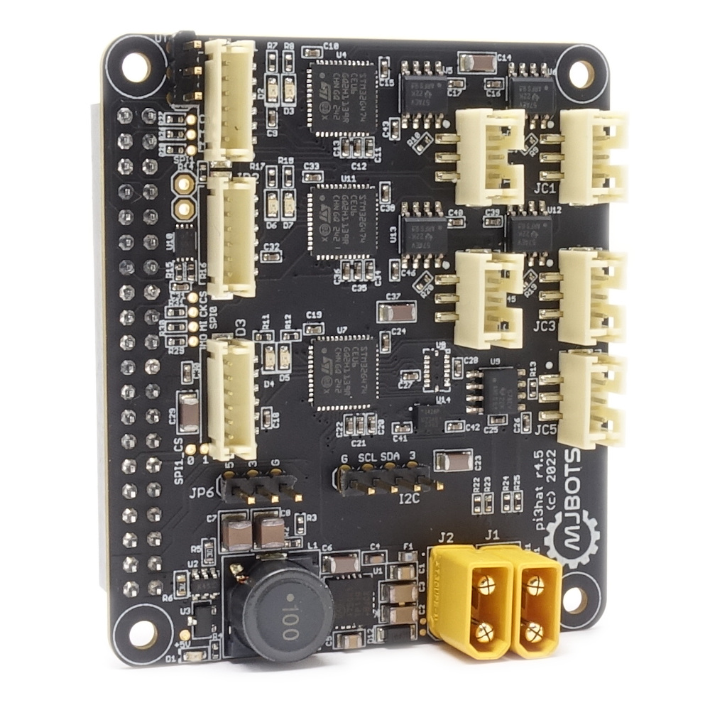
The Raspberry Pi 4 that runs the software has a mjbots pi3hat attached. That powers the rpi from the 24V input and also is used for a CAN connection to the power_dist board. A quick 3D printed mount holds it together and lets it clip onto the frame.

A hall sensor is mounted on the spring clip, so that the test application can automatically start the test cycle when the handle is fully closed.

Operation and Software

The software used is a derivative of the software used for the previous test fixture. First, it was updated to use the I/O expander board to take all the new measurements, such as verifying that all the ground and power pins on each connector are working properly, as well as all the additional GPIOs. Second, and more obvious, is that it was updated to use the python textual library to create a two-paned application.

One pane shows the ongoing results of the current board being tested, and the other pane shows the previous board’s results. The script was also updated to play an audible sound when a board is ready to be removed, so that uploading results from the previous board can take place in parallel with the beginning of the next test cycle.

Conclusions and Future Work

With this fixture, it is possible to reliably test and package more than 70 boards an hour, including all the additional test coverage. That is up from around 30-40 boards per hour with the old fixture. While the r4.11 has less need for side probing, it is still possible that a fixture based on this designed for it will be made at some point, if nothing else to add verification of the ABS port and the improved test cycle time.

power_dist r4.5b

Here is yet another new product announcement! In the same line as the new pi3hat, here is a new minor revision of the power_dist, the r4.5b:

The changes are largely the same as for the new pi3hat:

  • The input voltage range is extended from 10-44V, to 10-54V.
  • The CAN-FD port has +-58V bus fault protection, up from +-12V.
  • Additionally, the measurement noise of the output current has been improved from 300mA to approximately 30mA.

Check it out at mjbots.com today!

pi3hat r4.5

I’m excited to announce a minor upgrade to the mjbots pi3hat product line, the pi3hat r4.5!

This has a few upgrades over the old r4.4b:

  • The input voltage range is expanded from 8-44V to 8-54V.
  • All CAN-FD ports have +-58V bus fault protection, up from +-12V.
  • 0.1″ pin headers are present for the Raspberry Pi I2C, UART, and for 3.3V and 5V outputs

Check it out at mjbots.com today!

Updated moteus test fixture

I documented the first test fixture I built for moteus some time ago. As the shipment volumes have gone up, the fixture became something of a limitation, and also was a little problematic in a few ways.

The old “state of the art”

First, it relied on attaching 3 connectors by hand for each test, which was a decent fraction of the cycle time. Second, the pogo pins it used were non-replaceable, and also connected only to the debug phase wire test vias, which were tiny. They wore out relatively quickly, and replacing them required building a whole new board. Finally, since the pogo pins were PCB mounted, a PCB needed to be printed for any change in the pin locations or which pins to probe.

New fixture

Enter the new fixture:

From the side
With no board installed
Without the top platen
Lid raised, showing board contacts

This one uses modular test probe receptacles with replaceable tips, so that the tips can just be swapped out as they wear. These don’t appear to be available in an inexpensive manner in the US, but aliexpress has many options with 5 or 6 probe types in many sizes.

Second, the receptacles are all aligned with a 3D printed baseplate and platen to align them before contacting the PCB. This works alright down to the 1.5mm spacing test points on moteus, although that pitch is pushing what can be achieved with a 3D printed part.

Third, power, CAN, and the debug serial connections are now all probed from the bottom, so only one connector, the SWD programming port needs to be connected by hand.

Finally, the whole structure, including the top clamp is 3D printed now, which makes it potentially possible to do top probing and more easily adjust the dimensions.

With this new fixture, my cycle time for a test is around 60s. At that point, the time spent in the test program is about the same as the time it takes to unpack and package up the boards, so it isn’t really the limiting factor any more.

moteus r4.11

Here’s yet another update to the moteus line, moteus r4.11!

r4.11 is electrically, mechanically, and software compatible with r4.3, r4.5, and r4.8.

This revision supports two alternate footprints for the CAN-FD transceiver to better support component availability and refines the power stage for the DRV8353 gate driver. moteus r4.8 was the first version to use the DRV8353 because of, once again, component availability issues. However, it was developed on a very abbreviated schedule. With r4.11 the EMI is much improved over r4.8 and r4.5, and the efficiency is much better than r4.8 at all input voltages and PWM frequencies.

PWM Frequency24V r4.1124V r4.836V r4.1136V r4.8
15kHz95% / 0.28W94% / 0.20W95% / 0.30W92% / 0.25W
40kHz93% / 0.35W88% / 0.25W90% / 0.38W85% / 0.30W
50kHz91% / 0.36W84% / 0.30W89% / 0.40W84% / 0.35W
moteus r4.11 and r4.8 thermal efficiency and idle power driving nearly stationary motor

The matching development kit will be available shortly, once the r4.8 developer kits sell out.

power_dist load test circuit

While testing some variants and new versions of the power_dist board, I wanted to be able to simulate the types of loads that it experiences with a fully loaded robot. Some things are easy, like this capacitor attached to an XT30 connector:

I also have giant power resistors in a similar form factor:

However, a dumb load resistor isn’t a particularly representative load. Most likely, the loads that a power_dist will drive are active loads with switching regulators. When the output voltage is lower, the current will be correspondingly higher. That is especially important when validating pre-charge behavior, because it means that the current is much higher during the initial pre-charge window than it would be for a pure resistive load.

Thus, I made a tiny switching regulator to which I can stick a load resistor to the output.

Unfortunately since MacroFab discontinued their prototype tier, it no longer is as convenient to get one offs populated in the US. So this one I did by hand with a stencil, solder paste, a 3D printed frame, and some new tools, a vacuum pick, and a hot plate. I discovered you can get room temperature stable solder paste now — how convenient!

There were a few bugs… I managed to not have 0603 resistors for the voltage sense divider on hand, but had 0402 of the right values so just stuck a blob of solder to connect them. On the same resistors, I also managed to get the PCB labels swapped. Fixing that resulted in a board that does what it is supposed to!

moteus r4.5

Meet the newest revision of the moteus controller!

Yes, it does look mostly the same as the r4.3 that has been getting a lot of use lately. This revision exists mostly to improve manufacturability, but I snuck in a minor design improvement while at it. Now, the maximum voltage input is rated up to 44V from the 34V of the r4.3! (Note though, that the pi3hat and power_dist still are limited to 34V). Otherwise the new controller is fully electrically, mechanically, and software compatible with the r4.3.

It is now the default in the mjbots store, only $5 more than the old version at $84.

And, by popular demand, it still has a devkit!

More MLCC learning

It seems that I’m learning much about PCB design the very hard way.  Back last year I wrote up my discovery of MLCC bias derating.  Now I’ll share some of my experiences with MLCC cracking on the first production moteus controllers.

When I was first putting the production moteus controllers through their test and programming sequence, I observed a failure mode that I had yet to have observe in my career (which admittedly doesn’t include much board manufacturing).  When applying voltage, I got a spark and puff of magic smoke from near one of the DC link capacitors on the left hand side.  In the first batch of 40 I programmed, a full 20% failed in this way, some at 24V, and a few more at a 38V test.  I initially thought the problem might have been an etching issue resulting in voltage breakdown between a via and an internal ground plane, but after examining the results under the microscope and conferring with MacroFab determined the most likely cause was cracking of the MLCCs during PCB depanelization.

dsc_0415
A very obviously cracked capacitor

Here’s a video describing the problem and potential solutions in way more detail than I’ll go into:

Needless to say, I hadn’t managed to see this failure in the 100 or so previous moteus controllers I’ve built, or I would have figured this out and resolved it!

For this first round of production controllers, I went and replaced every single capacitor near the edge of the board with a TDK variant that has internal soft termination, then tested them all at max voltage and a little beyond.  Future revisions will use that variant of capacitor everywhere, as well as relocating the capacitors to reduce the mechanical stress they experience during manufacturing, handling, and installation.

Programming and testing moteus controllers

Like with the fdcanusb, I built a programming and test fixture for the moteus controllers.  The basic setup is similar to the fdcanusb.  I have a raspberry pi with a touchscreen connected via USB to a number of peripherals.  In this case, there is a STM32 programmer, a fdcanusb, and a label printer.  Here though, unlike with the fdcanusb fixture, I wanted to be able to test the drive stage of the controllers and the encoders too.

My solution was to create a mechanical fixture that each board slots onto, with pogo pins that connect to test points for the phase outputs.

dsc_0428

While it doesn’t make as good a connection as the solder through holes normally used to connect a motor, it is good enough to verify that the controller works.  As a side-bonus, it also makes it trivial to test that the absolute magnetic encoder works properly.

This video shows how the programming and testing process works, and walks through testing a few boards.

Power distribution board r3

While I was able to make the r2 power distribution board work, it did require quite a bit more than my usual number of blue wires and careful trace cutting.

dsc_0394

Thus I spun a new revision r3, basically just to fix all the blue wires so that I could have some spares without having to worry about the robustness of my hot glue.  While I was at it, I updated the logo:

dsc_0393

As seems to be the way of things, a few days after I sent this board off to be manufactured, I realized that the CAN port needed to actually be isolated, since when the switches are off, the ground is disconnected from the rest of the system.  Sigh.  Guess that will wait for r4.

Here is r3 all wired up into the chassis:

dsc_0395