As of release 2023-09-26, moteus controllers can now use CUI AMT21 series encoders for any encoder source. CUI’s AMT21 series encoders are rugged, with resolution up to 14 bits, and since they use RS485 for communication can be located a significant distance from the motor driver if necessary. Setting one up is easy with the moteus-n1, which is what I’ll cover here.
Hardware
The moteus N1 has JST GH-6 connector labeled “RS422” with all the pins necessary to power and communicate with an AMT21. Since the AMT21 is RS485, not RS422, it is required to tie the A and Y pins together and the B and Z pins together. An easy option is to do so in the harness, either by crimping multiple wires into the Molex terminal for the AMT21, or by splicing wires. The desired schematic looks like:
Software
With the moteus-n1, the software configuration is straightforward, and basically the same as for the AksIM-2.
Once the aux1 UART is configured, then it can be selected as the source for any of the motor_position sources and selected for either commutation sensing, output/load sensing, or as an auxiliary sensor. For instance, to use it as the primary encoder instead of the onboard one, you would do:
motor_position.sources.0.aux_number 1
motor_position.sources.0.type 2       # uart
motor_position.sources.0.cpr 16384    # AMT21 devices report as 14 bit
motor_position.commutation_source 0
motor_position.output.source 0
moteus-r4
As with the AksIM-2, a moteus-r4 can be used to drive the CUI AMT21 series, but additional interface hardware is required. An example schematic can be found in the “RLS AksIM-2” section of the initial “worked examples” post.
As of release 2023-09-26, moteus r4 and moteus-n1 now both support the MA732 as an external SPI encoder. The magnetic sensing performance of the MA732 is normally a bit worse than the AS5047P that is used as the onboard encoder with moteus, but it has two possible advantages.
The first, is that it is much smaller, using a 3mm x 3mm QFN package. The second is that it supports off-axis applications. You will need to read the datasheet, and set the 'aux?.spi.bct' configuration parameter correctly, but this can enable operation in interesting geometries, like a ring magnet with a hollow shaft, or where the coaxial placement is otherwise not feasible.
It has been on github for a few days now, but I’m excited to announce the newest moteus firmware release, 2022-07-11. This release includes some big features, and some quality of life improvements all around.
Flexible I/O subsystem: This release includes the new flexible I/O subsystem. This adds support for many new encoder types and lets you connect them up in a wide variety of ways.
Cogging torque compensation: Preliminary support for cogging torque compensation is present in this release. It works pretty well on a number of motor types already, future articles will describe it in more detail.
Encoder eccentricity compensation: This feature lets you linearize the output position and velocity in the face of non-linear encoder readings. A write-up for it is also forthcoming in the not-too-distant-future.
Transparent no-BRS CAN-FD communication: If your CAN-FD network is only capable of operating at 1Mbps, and you send queries frames with BRS turned off, moteus will now respond in kind. This eliminates most needs to change the CAN bus frequency due to marginal electrical properties.
This is an exciting time for moteus, and the new features will keep coming!
Third, the official reference documentation can be read here. This describes in detail all of the possible configuration values.
With those niceties out of the way, lets get into the examples!
1: Onboard AS5047P
This configuration is the default for moteus, and uses the onboard absolute AS5047P magnetic encoder for all positioning.
Torque: Yes
Velocity: Good
Position: Good
Configuration: This is the default for moteus, so no configuration is required.
Discussion: This configuration provides a decent all-around compromise between complexity and performance. Torque control is available and velocity control is good outside of ultra-slow regimes. The position is absolutely known to within one rotation of the rotor, across power cycles.
2: Hall effects / hoverboard
Here, the built-in hall effect sensors from a brushless motor are connected to three pins on the ENC port (aux1). Hall effect sensors are sometimes the only sensored commutation method practical to integrate into a motor system, and are the most common means of providing commutation signals for things like hoverboard motors.
Torque: Yes
Velocity: OK
Position: Incremental Only
Hardware: First, for moteus r4.8/11, either a Pico-SPOX 6 connector (TE 5-1775444-6) must be soldered onto the blank ENC pads of a moteus board or a cable must be soldered directly on to the pads. Then a matching cable harness must be constructed to mate the motor’s hall effect sensors to the Pico-SPOX connector (Housing: Molex 0874390601, Terminal: Molex 0874210100). If the sensors require 5V, then a boost regulator and level translators will be required. Otherwise, the 3.3V output of the ENC port can provide up to 100mA of power to the sensors, and their outputs should be connected to the C, K, and O pins (4, 5, and 6 on the connector).
Configuration: This example requires both configuration and alternate options specified duration calibration.
conf set aux1.spi.mode 1      # disabled
conf set aux1.pins.1.mode 6   # hall
conf set aux1.pins.1.pull 1   # pull-up
conf set aux1.pins.2.mode 6   # hall
conf set aux1.pins.2.pull 1   # pull-up
conf set aux1.pins.3.mode 6   # hall
conf set aux1.pins.3.pull 1   # pull-up

conf set aux1.hall.enabled 1  # enabled

conf set motor_position.sources.0.type 4   # hall
To calibrate, two additional options must be passed:
--cal-hall              # Instruct moteus_tool to use hall effects
--call-motor-poles 30   # How many motor pole pairs are present
Discussion: Performance-wise, this is a relatively poor option. Torque control is available, which is mostly what is used in hoverboard applications. Since the effective encoder resolution is very coarse, velocity control only works well at moderate to high speeds (say 0.3 Hz or higher). Position control is *not* absolutely referenced (i.e. it starts from 0 every time you power on) and it is only good to around 4 degrees for 30 pole pair hoverboard motors. With the current moteus configuration options, there is often jitter when stopped when using velocity or position control.
3: External AS5047P
This configuration can be used when the performance of the onboard AS5047P would be adequate, but for whatever reason, the moteus controller cannot be positioned immediately behind the sense magnet.
Torque: Yes
Velocity: Good
Position: Good
Hardware: Like with the hall effect example, for moteus r4.8/11, this requires that a Pico-SPOX connector be populated on the ENC blank pads (TE 5-1775444-6) or that a cable be directly soldered to the pads. A cable must then be constructed to attach the external AS5047P to the mating Pico-SPOX connector (Housing: Molex 0874390601, Terminal: Molex 0874210100). All of the pins are required:
G: Ground
3: 3.3V
C: SPI chip select
K: SPI clock
I: SPI CIPO/MISO
O: SPI COPI/MOSI
As the SPI lines are high frequency, they must be relatively short (<20cm), and mounted in such a way to avoid electrical interference. That may require shielding around the cable, or around portions of the mechanical assembly.
Configuration: The following configuration changes are necessary from a default setup:
conf set aux1.pins.0.mode 2   # spi_cs
conf set aux1.pins.1.mode 1   # spi
conf set aux1.pins.2.mode 1   # spi
conf set aux1.pins.3.mode 1   # spi
conf set aux1.spi.mode 2      # ext_as5047
Discussion: After the hardware has been constructed and the above configuration changes made, use and performance is identical to the onboard AS5047P configuration.
4: Sine / Cosine
Some absolute encoders emit their output in the form of two analog signals, the “sine” and “cosine”. For a given angle, each signal emits an analog voltage biased about a non-zero operating point based on its namespace. If the sine and cosine are 3.3V level, or can be downshifted using a resistive divider to fit within that range, then they can be used with moteus.
Hardware: Like with the hall effect example, for moteus r4.8/11, this requires that a Pico-SPOX connector be populated on the ENC blank pads (TE 5-1775444-6) or that a cable be directly soldered to the pads. A cable must then be constructed to attach the encoder to the mating Pico-SPOX connector (Housing: Molex 0874390601, Terminal: Molex 0874210100). The sine and cosine channels must be connected to one of:
ENC pin 4 / K / aux1 pin 1
ENC pin 5 / I / aux1 pin 2
ENC pin 6 / O / aux1 pin 3
Any two of those may be used. The ground signal should be connected, and the 3.3V signal can be used to provide up to 100mA of power to the target encoder.
Configuration: The following configuration changes are required from a default setup:
conf set aux1.pins.1.mode 8           # sine
conf set aux1.pins.2.mode 9           # cosine
conf set aux1.spi.mode 1              # disabled
conf set aux1.sine_cosine.enabled 1   # enabled
The next value must be calibrated. The raw values of the sine and cosine channel can be observed in telemetry as the encoder rotates through several revolutions. Take the midpoint, and use it below:
conf set aux1.sine_cosine.common 1692 # from hand-calibration
Calibration requires no special options.
Discussion: As a sine/cosine encoder is just an alternate way of connecting a rotor absolute position sensor, the basic properties are the same as for the onboard AS5047P encoder. However, the analog signal has less effective resolution, and more noise than a digital encoder. Thus, the audible noise may be greater for a given selected encoder bandwidth, and the control performance may be worse.
5: Quadrature / Index (ABI)
A lowest common denominator of absolute encoders is the quadrature and index interface. Here, two digital signal lines step through a quadrature relationship as ticks on the encoder pass, and a separate “index” line becomes positive at the 0 point of the encoder. This does provide absolute positioning, but requires that the motor possibly spin through an entire rotation at power on in order to discover what that absolute position is.
Torque: Yes
Velocity: Good
Position: OK
Hardware: Like with the hall effect example, for moteus r4.8/11, this requires that a Pico-SPOX connector be populated on the ENC blank pads (TE 5-1775444-6) or that a cable be directly soldered to the pads. A cable must then be constructed to attach the encoder to the mating Pico-SPOX connector (Housing: Molex 0874390601, Terminal: Molex 0874210100). The three signals can be connected to any of the following pins:
ENC pin 2 / C / aux1 pin 0
ENC pin 4 / K / aux1 pin 1
ENC pin 5 / I / aux1 pin 2
ENC pin 6 / O / aux1 pin 3
The ground signal should be connected, and the 3.3V pin may be used to provide up to 100mA of power to the target encoder.
Configuration: The following must be changed from default (assuming that the I pin is connected to K/ aux1 pin 1, and the two quadrature lines are connected to I / aux1 pin 2, and O / aux1 pin 3.
conf set aux1.pins.1.mode 7         # index
conf set aux1.pins.2.mode 4         # quad_sw
conf set aux1.pins.3.mode 4         # quad_sw

conf set aux1.spi.mode 1            # disabled
conf set aux1.quadrature.enabled 1  # enabled
Quadrature encoders have a rated cycles per revolution or counts per revolution. The counts per revolution is 4x the cycles per revolution, and is what moteus requires. The following configuration is suitable for a 1000 cycle per revolution or 4000 counts per revolution encoder.
conf set aux1.quadrature.cpr 20000
conf set motor_position.sources.0.type 3    # quadrature
conf set motor_position.sources.0.cpr 4000
Calibration requires no special options.
Discussion: This option can provide nominally the same performance as the onboard encoder with two caveats.
First, a “homing” step must be performed before control can begin. This means that actuating the motor must be possible without damage from the turn-on state, and not incompatible with the end application.
Second, it is possible for counts to be “missed” because of electrical interference. This can result in decreased performance or loss of control depending upon the severity. Proper routing and shielding of quadrature lines are essential to robust performance. The aux1.quadrature.error diagnostic field can be used to monitor for events that are consistent with electrical interference (it is normal to start at 1 at turn-on).
6: I2C Disambiguator
Often a motor controlled by moteus drives a gear reducer before eventually driving the output. In such cases, the onboard moteus encoder is not able to uniquely determine which sector the reducer output is located. One means of resolving that ambiguity is to place a low-rate absolute I2C based encoder on the output shaft.
Hardware: The only pins that support I2C on moteus r4.3/5/8/11 are the two data pins on the ABS port (a JST ZH-4 connector). A harness must be constructed to connect those two signal lines. On an unmodified board, 3.3V resistive pullups are hard-wired onto the board. If a 5V sensor is desired, either a boost regulator will be required to operate it from the ABS port power, or a separate 5V regulator will be necessary to power it.
ABS pin 1 – 3.3V
ABS pin 2 / aux2 pin 0 – SCL
ABS pin 3 / aux2 pin 1 – SDA
ABS pin 4 – GND
Configuration: Assuming an AS5048B encoder is attached, the following configuration changes are required:
conf set aux2.pins.0.mode 13        # i2c
conf set aux2.pins.1.mode 13        # i2c
conf set aux2.spi.mode 1            # disabled
conf set aux2.i2c.devices.0.type 1  # as5048
conf set motor_position.sources.1.aux_number 2
conf set motor_position.sources.1.type.i2c 7     # i2c
conf set motor_position.sources.1.i2c_device 0
conf set motor_position.sources.1.cpr 65536      # for the as5048
conf set motor_position.sources.1.reference 1    # output
Since two encoders must be correlated, the sign and offsets should be manually calibrated. Set them such that motor_position.sources.0.compensated_value in the diagnostics pane increases in the same direction for both and that it is 0 for both at the same position. Additionally, the gear box reduction ration needs to be set.
conf set motor_position.sources.1.sign 1           # hand-calibrated
conf set motor_position.sources.1.offset 0         # hand-calibrated
conf set motor_position.sources.0.offset 0         # hand-calibrated
conf set motor_position.rotor_to_output_ratio 0.5  # reduction ratio
Discussion: The control performance of this example is identical to that of the primary encoder in use, which here would be the onboard AS5047P. The advantage is that the absolute position of the output shaft is known exactly at power on, even with the reducing stage.
7: Onboard + Quadrature Output
For this example, a high resolution quadrature encoder is used in combination with the onboard encoder to improve the velocity and position tracking performance of the controller.
Torque: Yes
Velocity: Excellent
Position: Excellent
Hardware: Since the onboard encoder is being used, the quadrature encoder must be connected to the 2 pins on the ABS port (aux2) using a JST ZH-4 connector.
ABS pin 1 – 3.3V
ABS pin 2 / aux2 pin 0 – Quadrature A
ABS pin 3 / aux2 pin 1 – Quadrature B
ABS pin 4 – GND
Configuration: This configuration assumes that a 5000 cycle per revolution / 20000 count per revolution encoder is being used. For that, the following changes must be made:
conf set aux2.spi.mode 1             # disabled
conf set aux2.pins.0.mode 4          # quad_sw
conf set aux2.pins.1.mode 4          # quad_sw
conf set aux2.quadrature.enabled 1   # enabled
conf set aux2.quadrature.cpr 20000

conf set motor_position.sources.1.aux_number 2
conf set motor_position.sources.1.quadrature 3    # quadrature
conf set motor_position.sources.1.cpr 20000
Since multiple encoders are being correlated, we need to manually inspect the motor_position.sources telemetry view to identify if both sources increase as the output is moved in the same direction. If not, then the sign of the quadrature source should be -1.
conf set motor_position.sources.1.sign -1
Finally, the output position is configured to be derived from the quadrature signal, with a reference source from the onboard encoder so that it starts at the correct absolution position.
conf set motor_position.output.source 1
conf set motor_position.reference_source 0
Discussion: For this example, a quadrature encoder of much higher resolution than the onboard encoder was selected. Thus the resulting control performance has improved control at very low speeds, and improved position stiffness at any speed. The relative performance gain is directly proportional to the increase in effective resolution.
8: RLS AksIM-2
The RLS AksIM-2 is an encoder that reads a ring with magnetic tracks encoded on it to produce high resolution absolute position. It can be used when a hollow shaft is desired, or when high performance velocity control or high stiffness position control is required.
Torque: Yes
Velocity: Excellent
Position: Excellent
Hardware: moteus only supports the RS-422 asynchronous serial configuration of the RLS AksIM-2. The exact part numbers used in this demonstration are:
MB049SFF17BDNT00 – encoder
MRA049BG034DSN00 – magnetic ring
ACC049 – development cable
It requires the two data pins on the ABS port of moteus r4.3/5/8/11. To use it, a RS-422 level transceiver is required. One option which has been demonstrated to work is the MAX3490. Additionally, the AksIM-2 requires 5V power, this can be provided via a boost regulator driven from the ABS port or a separate 5V regulator.
ABS pin 1 – 3.3V
ABS pin 2 / aux2 pin 0 – RX
ABS pin 3 / aux2 pin 1 – TX
ABS pin 4 – GND
Configuration: The required configuration is straightforward. This example will leave the onboard encoder configured, but it could also be disabled if not used. It also assumes that the AksIM-2 has been configured ahead of time (either at the factory or using RLS tools) to 1000000 baud.
conf set aux2.pins.0.mode 3   # uart
conf set aux2.pins.1.mode 3   # uart
conf set aux2.spi.mode 1      # disabled
conf set aux2.uart.mode 1     # aksim2
conf set aux2.uart.baud_rate 1000000

conf set motor_position.sources.1.aux_number 2
conf set motor_position.sources.1.type 2        # uart
conf set motor_position.sources.1.cpr 4194304   # 22 bits (for any AskIM-2)

conf set motor_position.commutation_source 1
conf set motor_position.output.source 1
Discussion: This example provides excellent control performance both at very low speeds, high position stiffness, and gives a hollow shaft capability. The primary downsides are complexity and cost. An active adapter is required, and in single unit quantities, the AksIM-2 and an encoder ring is more than twice as expensive than a moteus itself.
9: iC-Haus iC-PZ
The iC-Haus iC-PZ is a reflective optical encoder that reads a marked code ring. It is high resolution and accuracy and supports a number of communication interfaces. The only one that moteus supports currently is the SPI protocol.
Torque: Yes
Velocity: Excellent
Position: Excellent
Hardware: Like with the hall effect example, for moteus r4.8/11, this requires that a Pico-SPOX connector be populated on the ENC blank pads (TE 5-1775444-6) or that a cable be directly soldered to the pads. A cable must then be constructed to attach the external AS5047P to the mating Pico-SPOX connector (Housing: Molex 0874390601, Terminal: Molex 0874210100).
Additionally, while the iC-PZ can provide 3.3V compatible I/O pins, and thus no SPI level translation is required, it also requires a 5V supply. Thus either a boost regulator is required to use the ENC port provided 3.3V power, or a separate 5V supply is needed.
All of the pins are required:
G: Ground
3: 3.3V
C: SPI chip select
K: SPI clock
I: SPI CIPO/MISO
O: SPI COPI/MOSI
Configuration: The iC-PZ requires a moderate amount of provisioning before it will produce usable values. While it is possible to do so using only diagnostic mode commands with moteus, the process is involved enough that it is not recommended. Instead, this configuration assumes that the encoder has been provisioned using the iC-Haus tools first.
conf set aux1.pins.0.mode 2  # spi_cs
conf set aux1.pins.1.mode 1  # spi
conf set aux1.pins.2.mode 1  # spi
conf set aux1.pins.3.mode 1  # spi

conf set aux1.spi.rate_hz 6000000
conf set aux1.spi.mode 3           # ic_pz

conf set motor_position.sources.0.cpr 16777216   # 24 bits
Discussion: The iC-PZ provides the same benefits as the RLS AksIM-2 above in terms of improved control performance and hollow shaft capability. It still requires adapter hardware with moteus, although the required hardware is slightly less complex than with the AksIM-2. Also, it is lower cost, but does require a more complex provisioning stage and optical cleanliness.
10: Fixed Voltage
Sometimes you can’t fit an encoder into a design, but you still want low speed operation. For those cases, moteus can be configured to drive a brushless motor as if it were a stepper motor with micro-steps. This means that there is no velocity or position feedback, and the motor will constantly dissipate a roughly fixed power, even when stationary or unloaded.
Torque: No
Velocity: Poor
Position: Poor / Incremental Only
Hardware: No additional hardware is required.
Configuration: Auto-calibration is not possible in this mode, but the required configuration is minimal. The number of pole-pairs must be entered manually if the output is to be scaled correctly, and the fixed control voltage must be specified by the designer. A larger fixed voltage will dissipate more power but provide more holding torque.
conf set motor.poles 14   # the number of pole-pairs for the motor

conf servo.fixed_voltage_mode 1         # enabled
conf servo.fixed_voltage_control_V 0.3  # selected by the designer
Discussion: In most cases where you want to drive a motor in a stepper like manner, a dedicated stepper driver is more appropriate. However, if you already have multiple moteus controllers in your system, or you want to use the advanced trajectory controls, this might be a valid design choice.
11: GPIO
Any of the pins on any connector can be used for 3.3V digital input or output. Some pins can be used for 3.3V analog input, and some can be used for 5V digital input. A dedicated “function” on the aux port is not required, so any pins which are not otherwise needed for a function can be so configured.
Hardware: moteus does not require any specific hardware, although if you want to use a given digital input or output to do something, you will likely need to construct at a minimum a harness to connect it to one of the ENC or ABS ports.
Configuration: Each pin can be configured independently:
conf set aux2.pins.0.mode 14    # digital input
conf set aux2.pins.1.mode 15    # digital output
conf set aux1.pins.2.mode 16    # analog input
Discussion: Once configured, the digital readings from each pin are accessible in the auxN.pins diagnostic mode tree and by using the 0x05e or 0x05f register mode registers as 7 bit integer bitfields.
Writing to the digital outputs can be conducted with the diagnostic protocol as follows
aux1 out 33 # a decimal bitfield
or by using register mode registers 0x05c / 0x05d.
Finally, analog inputs can be read in the diagnostic tree at aux1.analog_inputs, and in register mode at registers 0x060 – 0x06c.
Conclusion
While the flexible I/O subsystem already enables a lot of new configurations for moteus, keep on the lookout as it makes even more things feasible in the future!
This will be the final post describing the fundamentals of configuring the new flexible I/O system. There have been a number of previous posts (part 1, part 2, part 3). In this iteration, we’ll cover how to configure the sinks that consume the “source” encoder data. As a reminder, the block diagram of the I/O system looks like:
Commutation
To perform commutation with field oriented control, moteus needs to know the relationship between the rotor and stator in the magnetic domain. With the addition of the new flexible I/O system, some of the configurable values associated with this remain as they were, where there are some new ones.
First, the number of poles for the motor is still at motor.poles, and whether or not to invert the ordering of the output phases is at motor.phase_invert. Similarly, the theta mapping table has the same semantics before and remains at motor.offset.
Newly added is motor_position.commutation_source which controls which 0 indexed source is used to drive commutation.
It is shown in the block diagram above, but not discussed here yet are the cogging compensation parameters. They’ll be covered soon, I promise!
Output
The other primary purpose of encoder data within moteus is to act as feedback to the position control loop. For this, the source to use can be selected with:
motor.output.source
Additionally, an offset and sign can be configured at this stage with motor.output.offset or motor.output.sign. A gear reducer can be configured by entering a non-unity value for
motor.rotor_to_output_ratio
Values here will typically be smaller than 1. For instance, a 1:4 gear reducer would be 0.25.
Finally, to support disambiguation after a reducer with low-performance sensors, a second source may be configured for that purpose with:
motor.output.reference_source
The “reference source” will be consulted only at system power on after it is valid, in order to resolve the ambiguity resulting from the reducer. It can also be used if the output is incremental, but another absolute source is present that is lower quality or lower rate, to reference the output at power on.
Application
There are no configurable values necessary to operate any of the new I/O system from the application level. There are new registers that can be used to read the position and velocity from each of the sources, whether or not they are configured for any sinks. Similarly, the digital input, digital output, and analog inputs can all be operated from the register or diagnostic protocol. All of these can be seen in the reference documentation.
In the last two posts (part 1, part 2), I started talking about the new, more flexible I/O subsystem for the open source moteus brushless motor controller. In this post, I’ll continue by describing what a “source” is, and how it is configured.
For reference, the block diagram showing how auxiliary ports, sources, and sinks are related is below:
Each “source” in the above diagram represents a single encoder. To the sinks it provides a position and velocity, along with various validity indications for that data. Each has three basic configuration components: where to get the raw data, how to transform that raw data, and the low-pass filter configuration. We’ll cover each in turn.
Source raw data location
The location where a source retrieves raw data is selected by picking the auxiliary port number to use (1 indexed, so 1 is auxiliary port 1) and which function within that auxiliary port the data should be retrieved from. For instance, if we want a quadrature encoder connected to auxiliary port 2 to feed into source 3, we would set:
There are two other minor complications. The first, is that for I2C functions, a separate configurable value is used to select which I2C device should be used.
motor_position.sources.X.i2c_index
If an “incremental” raw source is used, like quadrature, then an index function can be used directly at the source level to allow the source itself to report a correct absolute reading. This is necessary if the source is to be used for commutation. It is configured by entering the 1 based auxiliary port number into:
motor_position.sources.X.incremental_index
Source transforms
The are a number of transforms applied in sequence, each of which may be configured:
Offset: This is an offset in count space to add to the raw value before any other transformation is performed.
Sign: This may be 1 or -1. If -1, then the value will be inverted.
CPR: This is the “counts per revolution” and must be configured. For auxiliary port functions which have a CPR configuration, this must match it.
Eccentricity Compensation: A table of 32 points that describe percentage offsets from a perfectly linear response. It can be generated through a separate calibration tool, and all 0’s performs no eccentricity compensation.
The nominal output after all transforms have been completed is an angular position value between 0.0 and 1.0.
Low pass filter
The PLL based low pass filter is the final stage in the source pipeline. It is configured through a single parameter to select the 3dB cutoff frequency:
motor_position.sources.X.pll_filter_hz
If the encoder is intended to be used for either commutation or for output position control, this frequency should be at least as large as the mechanical bandwidth of the system and at least as large as the torque bandwidth for stable control. Higher values than that trade off audible noise versus control performance.
Reference frame
Each source can be configured to be in one of the “rotor” or the “output” reference frames. This controls whether the rotor to output ratio is applied when using the value for either commutation or output control.
motor_position.sources.X.reference
Where 0 is used for rotor and 1 is used for output.
Nearly done with configuration
I’ll tackle the final part of configuration in the next post, the sinks that use this encoder data.
In the last post, I covered the goals behind more flexible I/O support in the moteus brushless controller. This time, I’ll start to cover the configuration model that I implemented to make that support work. It is broken up into 3 distinct phases, auxiliary ports, sources, and sinks.
Slightly simplified I/O structure flow diagram
Auxiliary port pin configuration
To begin with, the available connectors and external pins on moteus are organized into “auxiliary ports”. For the moteus r4.3/4.5/4.8/4.11, the correspondence is that the external primary encoder connector, if present (r4.8 and newer), is “auxiliary port 1”. The ABS port and some on-board debug pads are “auxiliary port 2”. For each port, there are two levels of configuration, at the pin level and the function level.
At the pin level, each pin can be assigned to exactly one possible function from the available set. The possibilities include each of the possible encoder functions, as well as digital input output, or analog input. For each board, not all pins are capable of all functions, if an unsupported configuration is attempted, it just results in a runtime error. The current set of capabilities for the connectors available on moteus r4.11 looks like:
Some modes can be assigned to any pin no matter the board version. These modes are digital input or output, hall effect input, software based quadrature, and index input.
The pin configuration is selected by a single enumeration for each pin, located at aux[12].pins.X.mode. Additionally, a pull-down, pull-up, or open-collector can be configured for each pin at aux[12].pins.X.pull, although not all functions and pins support all pull-up values. For instance, analog inputs do not support pull-up or open-collector, and digital outputs support no pulls at all.
Note that the pin number in configuration is the “logical pin” number and is listed in the “Aux” column of the above table. It basically counts from 0 starting at the first pin available for input or output.
Auxiliary port function configuration
After the pins are configured, each of the possible functions on an auxiliary port has a configuration section which allows it to be enabled, and in most cases provides additional options as well. If a function is enabled, but pins with appropriate capabilities are not configured for that function, then a runtime error is generated.
The functions that are currently implemented and their configuration options are:
SPI: Whether an AS5047 or a iC-PZ encoder is present, and what bit-rate the SPI bus should operate at.
UART: The only supported type currently is the RLS AksIM-2. The baud rate and polling rate can be configured.
Quadrature: The counts per revolution.
Hall effect: A bitfield describing the polarity of the 3 hall effect inputs.
Index: None
Sine/Cosine: The neutral value can be configured as measured by a 4096 count ADC converter (this usually must be calibrated).
I2C: The I2C bitrate and mode can be configured, along with up to 3 different I2C devices. For each device, the address and polling rate can be selected. Currently available devices are the AS5600 or the AS5048A.
Notably, with the exception of I2C, only one instance of each function can be enabled for a given auxiliary port. Thus it is not possible to have two independent quadrature encoders connected to a single auxiliary port, even if the available pins would otherwise permit it. Digital input, digital output and analog input do not require a “function”, so as many of those may exist as desired.
Next up
In the next post, I’ll cover how the sources section of the above diagram is configured.
The moteus controller, being a brushless servo drive, needs to use encoders to measure things like how the rotor is positioned relative the stator, and possibly output shafts that have passed through a reducing stage. The support for this has gradually expanded over time, but is still relatively limited as far as those things go. The available options are:
However, the moteus hardware has always been capable of more, both because the processor is a very capable one, and the exposed IO pins are relatively flexible. While looking at some future designs that incorporate even more IO options, I decided it was time to update the firmware to finally start taking advantage of that flexibility.
My goals can be broken down into two parts. First, what types of IO (input/output) to support, and second, how those inputs and outputs can be used.
I/O Support
For the types of encoders, there are first a number of “primitive” types that are somewhat like common interchange formats for encoders:
Index – Here a single digital line is used to indicate when the rotating device is at a fixed position.
Sine / cosine – Two analog values report the sine and cosine of the angular position.
Hall effect sensors – Many brushless motors have 3 hall effect sensors permanently mounted inside which, while it cannot determine the position of the rotor relative to the stator fully, can determine the electrical phase configuration.
Second, there are a number of digital sensors which are relatively common in servo applications that are moderately convenient to interface.
iC-PZ – This is an absolute optical reflective encoder from iC-Haus which has relatively loose mechanical tolerances and very high resolution. It supports a number of protocols, multiple of which could work with moteus. Many diameter code rings are supported for hollow shaft applications.
RLS AksIM-2 – This is an absolute magnetic encoder with similar performance properties to the iC-PZ and also supports a variety of code ring diameters.
Third, the exposed pins of moteus could be used for application specific purposes:
Digital input – Some of the STM32 pins support 5V tolerant inputs, and all support 3.3V
Digital output
Analog input
Step/direction control
RC PWM/PPM input
How they can be used
There are a number of ways that encoders can be used, and it would be nice to be able to use some or all of them in different applications:
Electrical commutation – Determine the electrical phase for performing field oriented control.
Output position control – Provide feedback to the servo position and velocity control loop.
Disambiguate gear reducers – When an absolute sensor is present before a gear reducer, a separate sensor of lower quality can be used to determine in which sector of the output the reducer is currently in.
Application monitoring – In some cases, moteus may not need to use the value at all, but the application would like to monitor the position or rate of an encoder that happens to be colocated with a moteus.
Next steps
In the next post, I’ll take a look at the configuration model I implemented to support these goals in moteus!
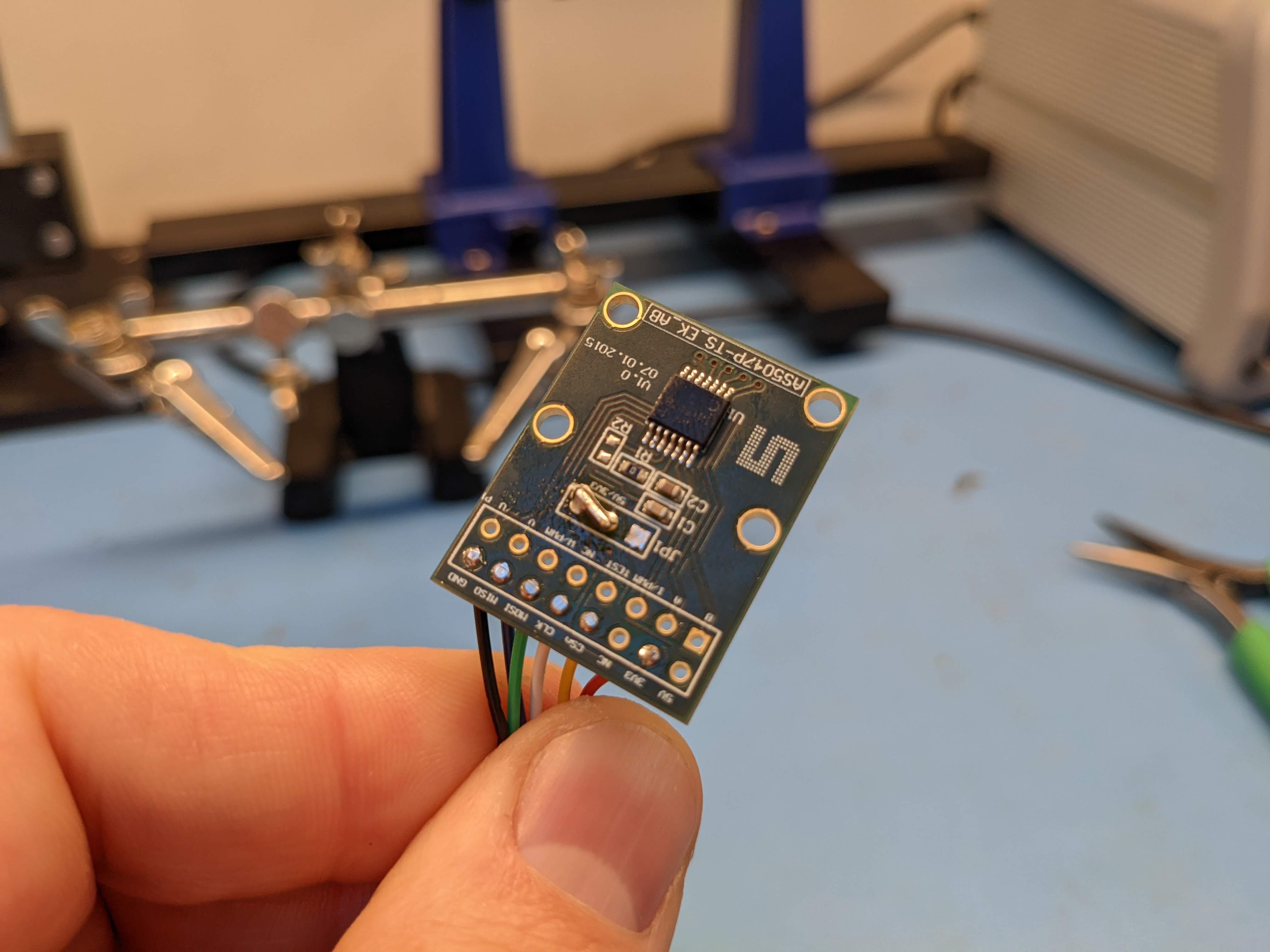
With the r4.8 release of moteus, a not-yet-announced feature was included — the ability to have an off-board primary encoder! It didn’t get announced at the time, because the connectors necessary to populate the board were not obtainable. In fact, that is still the case, but I’ve located a substitute part which works well enough, so here we go!
Theory
The moteus controller uses an absolute magnetic encoder to determine the relationship between the rotor and stator of the motor at each given instant. That allows it to produce torque in the motor at any speed, from standstill to the maximum possible speed. Until now, the only magnetic encoder that was supported is the one mounted to the backside of the board. This is largely acceptable, as moteus is intended to be used in integrated applications.
However, some users like the moteus form factor and capabilities, but don’t have room to put the entire board right next to the sense magnet. Now the pads on the back can be used for just that:
These pads contain SPI signals that can be optionally configured to enable an external primary encoder. As of now, the only encoder IC supported is the same one that is mounted on the board, the AS5047P (or anything with an identical SPI protocol).
Usage
To use this mode, you need to connect the external AS5047P IC to the pads on the back of moteus. You can do that with either connectors, or by soldering bare wires to the pads. The following connector set is in stock at Digi-Key as of 2022-03-07 and is compatible:
To use this, you need to position the jumper to connect the 3.3V supply as the primary source. In my example here, I pulled out the pins and soldered a bridge across it so it could fit flush against a motor.
AS5047P breakout configured for 3.3V
Finally, you need to enable the external encoder in configuration:
encoder.mode – Set to 1 for an external AS5047 SPI compatible encoder
At this point, the motor can be calibrated as usual.
Limitations
As moteus uses a high bit-rate for SPI (12Mhz), the allowable connection length is short, <20cm is recommended. The wires will be somewhat sensitive to interference, so the allowable length may be even shorter for environments with large amounts of EMI.
While encoders other than the AS5047 may be supported in the future, the possibilities are somewhat limited due to the way moteus samples the encoder currently.
TLDR: moteus can now filter the encoder, resulting in less audible noise. Use firmware version 2021-04-20 and ‘pip3 install moteus’ version 0.3.19, then re-calibrate to get the benefits.
Background
The moteus controller uses an absolute magnetic encoder to measure the position of the rotor. It uses this knowledge to accurately control the current through the three phases of a brushless motor so that the desired torque is produced, i.e. “field oriented control”. This works well, but has some downsides. One, is that magnetic encoders work by sensing the magnetic field produced by a “sensing magnet” that is somehow affixed to the rotor. This sensing process always introduces some noise, so that the sensed rotor position is never perfect.
Because of this, even if the rotor is perfectly stationary, moteus will constantly be tweaking the phase of the motor current to track the noise. This results in slightly increased power consumption, and more important to most, audible noise as the slight variations in control current can induce vibrations in the phase windings of the motor.
Fortunately, in most applications, the rotor is not actually capable of accelerating with the full bandwidth that the magnetic sensor is capable of sensing. Thus, we can filter it to remove high frequency noise without any loss of performance.
Approach
The filter method that moteus uses is an “all-digital phase locked loop“. Formulated in the traditional PLL terminology, this consists of three pieces: a numerically controlled oscillator, a phase detector, and a PI controller.
The “numerically controlled oscillator” is just a counter that tries to “guess” what the encoder is doing by propagating a value forward at an estimated velocity. For an ADPLL in this setup (where our encoder gives us an absolute phase measurement), the “phase detector” just subtracts the measured phase from the estimated phase. The PI controller determines how the estimated oscillator tracks disturbances in the actual encoder frequency.
In my post on automatic torque bandwidth selection for moteus, I derived the necessary equations for determining the torque bandwidth. Here, I’m just going to reference the excellent article by Neil Robertson, “Digital PLL’s” (part 1, and part 2), over at dsprelated.com. There, he derived the necessary proportional and derivative gains for a given bandwidth and damping ratio:
Where is the “damping ratio“. For our purposes, we’ll use 1.0, which is known as “critically damped” and is often a good balance between stability and response time.
Experiments
To see this in action, I ran some experiments on a moteus devkit. I added back in a conditional ability to emit a few bytes of debugging information at the full control rate to the firmware, and used that to emit the encoder value as used by FOC at each control cycle. I made up a script, that can plot the power spectral density in the encoder measurements. This is basically the noise present at any given frequency. When run on an unmodified development kit with no encoder filtering, the result looks like:
Power spectral density of moteus AS5047P encoder in a devkit
This shows that there are peaks in the noise at around 700Hz and 2kHz and after that the noise drops off rather rapidly. Then if we enable filtering at a few different bandwidths, you can see how the plot changes:
Power spectral density of AS5047P with various filter bandwidths configured
The filter bandwidths here varied from 5000 rps (~800Hz) down to 100rps (~15Hz). The filtered noise profiles follow what one would expect for each of the filters.
Audible noise
To measure the combined effect of this and torque bandwidth on audible noise, I switched to a controller attached to an 8108 motor, as I’ve seen those tend to demonstrate more audible noise. The motor had a constant back and forth motion at 0.5Hz for 60s and the result was captured with a studio mic set about 1cm away from the motor. In each test, I ran moteus_tool --calibrate and selected only a torque bandwidth, letting it pick an appropriate encoder bandwidth. For the 100Hz torque bandwidth and above tests, the same position PID values were used, although they needed to be tweaked for stability at the lower bandwidths. I similarly plotted the power spectral density for several filtering values and for silence. The total signal strength measured in negative dB is noted in the label:
It is not shown here, but the unfiltered noise is about the same as the 400Hz one. Thus, the maximum improvement is around 6dB of audible noise. Filtering at 100Hz gives most of that benefit for this motor, with slight improvements beyond that. Most of the audible energy is in the spectrum below 1kHz and there are several frequency bands where the encoder does not appear to be the dominant source of audible noise, as all options are equivalent in those.
For comparison purposes, the ODrive firmware defaults to filtering both the torque and encoder at around 160Hz (1000rps).
moteus_tool integration
As of version 0.3.19, moteus_tool has support for configuring the encoder bandwidth during calibration. By default, it will select a value appropriate for the selected torque bandwidth, or you can specify it manually with --encoder-bw-hz.


 is the “


