Tag Archives: gearbox

Making the reduced weight servo mk2

Earlier I described my design plan for reducing the overall mass of the moteus servo mk2.  Constructing a prototype of this turned out to take many more iterations and time than I had expected!  Along the way I produced and scrapped two front housings, two outer housings and a back housing.

dsc_0095
Soooo much PocketNC time for naught!

I made one complete prototype which only had the weight reduction applied to some of the parts and lacked a back cover and any provision for a wire cover.  It was the one from the moteus controller r4.1 juggling video:

dsc_0098

dsc_0096-1

Because of the multiple tries on the large-for-me front and back housing, I had to make soft-jaws and prepare stock in a more efficient manner.

I also had to get new workholding solutions for the PocketNC in the form of the wcubed vise.

Design updates

Every one of the pieces got reworked in some manner or designed from scratch for the things that did not exist previously.

Front housing: Here I iterated on how much material to remove from the central cavity.  Initially I removed more, but it gave the primary output bearing problems to be loaded intermittently.  Also, I had adhesion problems with the ring gear when too little material was left there.  I settled on a continuous ring for the output bearing and a decent amount of material for the internal gear.

20200107-front-housing-left20200107-front-housing-right

Back housing: I tweaked the back housing mounting points so that the outer housing could be symmetric.  Also, I added a facility for the wire cover to guard the phase wires entering the controller.

20200107-back-housing-left20200107-back-housing-right

Outer housing: The outer housing was largely unchanged from my initial weight reduced design, although I produced one bad one due to a simple mistake locating the mounting hole, and a second because the stud lengths between the front and back were different in an earlier iteration.

20200107-outer-housing

Planet output: The planet output design changed only to add some weight reducing cutouts.  This was the last part for which I was still using mk1 servo spare parts for, so now I actually manufactured a prototype in house.

20200107-planet-output-left20200107-planet-output-right

Planet input: Here there are now weight reducing cutouts, and the mating studs use less material.

20200107-planet-input-left20200107-planet-input-right

Back cover: The back cover design is basically unchanged, I just had to make one for the first time.

20200107-back-cover-left20200107-back-cover-right

Wire cover: The wire cover is a part of the design I had deferred until now.  It bolts to the back housing and shrouds the phase wires.

20200107-wire-cover-right.png20200107-wire-cover-left

Assembly

Here’s some assembly pictures:

dsc_0093
All the machined pieces prior to assembly


dsc_0099.jpg
Bearings installed in front housing and planet output

dsc_0101
Planet output and ring gear installed

dsc_0103
Stator installed

dsc_0104
Planets installed and pins in planet input

dsc_0106
Rotor and outer housing

dsc_0112
Back housing, controller, and wire cover

dsc_0113
All put together!

DSC00168

DSC00171


moteus servo mk2: Reducing weight

After having produced the first functional demonstration of the moteus servo mk2, my next step was to decrease the weight.  While I was at it, I made two other changes:

  • Axial connections: I switched to a design with entirely axial connectors, which removes the need for 4th axis machining when producing the parts.
  • Planet Input Bearing: I switched the planet input bearing to be inserted from the rotor side.  This way, the bearing is captured between the planet input and the rotor, rather than between the planet input and the gears.  That also improves the ability to assemble and disassemble the unit.

moteus_mk2_reduced_weight_2

Slimming down the housings drops around 100g from the total weight.  I may still try to take out some weight from the planet input and output, but they don’t weigh much to begin with so the potential gains there are small.

Next up I’ll manufacture and assemble this, then get it running.


moteus servo mk2: Functional test

Now that I have at least one functioning version of each of the pieces made for the moteus servo mk2 (planet input, outer housing, front housing, and back housing), I integrated all of them together into a functional prototype.

dsc_1841
A bunch of pieces

dsc_1842
Front housing with stator, internal gear, and planet output installed

dsc_1844
Planet input, gears, and shafts installed

dsc_1855
All put together… a bit on the heavy side for now

And finally, spinning it up!

moteus servo mk2

As described in my roadmap, making a new revision of the moteus servo is up there on my list of things to do.  The initial servos were a work of art, yes, but also pretty fragile, very labor intensive, and still not all that robust.  My goals this time around are:

  • Manufacturability: The servo mk1 took about 2 or 3 man-days of manufacturing time per servo once all the steps were factored in.  I’d like to get that down to an hour or two at most per servo.
  • Robustness: The planet input, outer housing, back housing, and controller cover of the mk1 servo were 3d printed, mostly to save cost and time.  This necessitated adding reinforcing rings on the outer housing, as it is nearly impossible to 3d print something with the required material properties in a single print.  At this point, all of these components should just be made of aluminum like the others.
  • Repairability: Once the mk1 was assembled, there was no way to disassemble it, as installing the stator interfered with the ability to remove the outer housing, and the outer housing in place interfered with the ability to remove the stator.
  • Convenience: The mk1 servo used the r3.1 moteus controller, which had RS485 connectors sticking straight out the back, and bare power wires coming out the back.  That orientation for connecting things was not terribly convenient in the full rotation leg design, and required making extension cables.  The newer moteus controller has the connectors sticking out the bottom, so the servo needs to accommodate that.

CAD explosion

moteus_mk2_side_view
CAD rendering

Changes in moteus servo mk2

The current design for the moteus servo mk2, as the exploded video above shows, has a number of changes.

First, the outer housing has been changed to be purely cylindrical.  This allows it to be machined out of round tube stock, and also assembled and removed in any order.  Thus the front housing now has a slightly larger outer diameter, and has threaded holes around the perimeter and 8 primary mounting holes instead of 6.

The rotor is custom machined, so that the sun gear holder assembly is no longer required.  A not shown in the explosing mini 3d printed adapter will hold the magnet and fit inside the rotor bearing on the back.

The planet input now has a small indexing slot to eventually register a magnet holding assembly that can be used to sense the position of the output stage, and a position sense board is installed in the front housing to sense it.

All of the gears are now custom manufactured (at shop.mjbots.com – Internal Gear, Planet Gear, Sun Gear).  This reduces the cost considerably, improves tolerances, and requires no post-machining.

The back housing has been updated to mount a newer moteus controller, provide heatsinking to it, and also be slightly slimmer due to being manufactured from aluminum.

The overall dimensions are approximately the same as the mk1, with the depth increasing by a few millimeters (largely because of the connectors on the new moteus controller), and the outer diameter decreasing by a few millimeters.  I believe I should be able to get the weight to be about the same as the mk1, around 430-450 grams.

Next steps

First, I’ll make a functional prototype to verify that all the parts fit together and work.  Then I’ll work to get the weight back down to closer to the mk1, after which I’ll start producing enough of these to make more robots.

shop.mjbots.com

In my quest to create a more dynamic quadruped, I’ve started accumulating a lot of parts from bulk buys that could be reasonably useful to other hobbyists and experimenters.  To maybe make life easier for everyone, I’ve started up what may be the worlds ugliest online shop where you can buy some of these components.  For now, I have some bearings and custom gears that are useful when building servos for dynamic robots.

Check it out! https://shop.mjbots.com

Unfortunately US shipping only for now, email me or DM on discord to arrange something internationally.

Some samples of what I have online now:

M0.5 100 Tooth Steel Ring Gear

m05_100tooth_internal_right

55mm +0/-0.02 mm outer diameter and 5mm width, only $17 each.

M0.5 20 Tooth Sun Gear

m05_20tooth_sun_front

5mm tooth width, 4mm ID bore, 8mm OD hub, only $6

6708-2RS ABEC-1 Bearing 40x50x6mm

6708-2RS-bearing-right

50mm OD, 40mm ID, 6mm width, only $8


mjbots quad A0: October 2019 Roadmap

My last video gave an overview of what I’ve accomplished over the past year.  Now, let me talk about what I’m planning to work on going forward:

I intend to divide my efforts into two parallel tracks.  The first is to demonstrate increased capabilities and continue learning with the existing quad A0, and second is to design and manufacture the next revision of all its major components.

New capabilities and learning

The first, and most important capability I want to develop is an improved gait and locomotion system.  While the moteus servos in the quad A0 are capable of high rate compliant control, the gait engine that I’m using now is still basically the same one that I made for the HerkuleX servos 5 years ago.  It just commands open loop positions to each of the servos and uses no feedback from the platform at all.  This severely limits what the robot can do.  For instance, if the terrain is not level, legs will drag on the ground or it will not walk at all.  The maximum speed is relatively slow and achieving it requires careful tuning of servo-level gains.  While it is more robust than nearly any other open loop 4 legged walker while standing up, even small disturbances can cause it to fall over.

At a minimum, I’d like to switch to controlling the position and force of the endpoint of each leg and switch to a gait engine that takes into account the actual position of each joint during the gait cycle.  That should enable it to maintain good ground contact with all feet that are intended to be in a stance position.  Now, often feet will skip around, as the servo gains are all relatively high to account for the lack of feedback.

The next level would be to take into account an IMU to ensure balanced feet lift offs.  While I have an IMU in this configuration, it currently isn’t usable due to my improvised attempts to improve the overall system update rate.  I’ll need to update some of the hardware to get an IMU again before I work on this part.

New hardware revisions

I have learned a lot with the moteus controller, servo, and the quad A0 over the last year.  I’d like to take that learning and update the components to achieve:

  • Manufacturability: Many of the sub components now are very labor intensive to produce or assemble.
  • Cost: I have in many cases made things much more expensive than they needed to be in order to shave a bit of time off the prototyping process.  Also, I have enough confidence now to get larger volumes of parts, which further reduces cost.
  • Capability: There are many easy areas where the system performance can be greatly improved.

My overall goals are to make a system that is capable and affordable — to provide an ecosystem of parts and systems for researchers and hobbyists to use.  That means keeping everything open source, and providing access to all subcomponents and designs while still being able to provide a complete system that is capable out of the box.

Here’s a quick rundown of the various areas I’m tackling:

Moteus controller

My next revision of this controller will be a slightly bigger change, in that the form factor, the microcontroller, and the connectors used will all be altered.  I’m planning on switching to an STM32G4 for the controller, using daisy-chained connectors for power in addition to communications, switching to FD-CAN for communications, and reworking the form factor to enable all the primary connectors to exit from one edge of the servo.

Also, I’ll take this opportunity to design for automated end of line test.  That means I will leave enough probe points such that a test fixture can validate the correct operation of a board without intervention.

I don’t anticipate the performance to change a whole lot, although I may increase the allowed input voltage.  Even so this will still be a very capable board, with 3 phase current sensing, >=50A peak phase current, >= 400W peak power and a switching and internal control loop rate of >=40kHz.
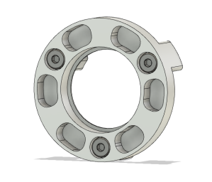
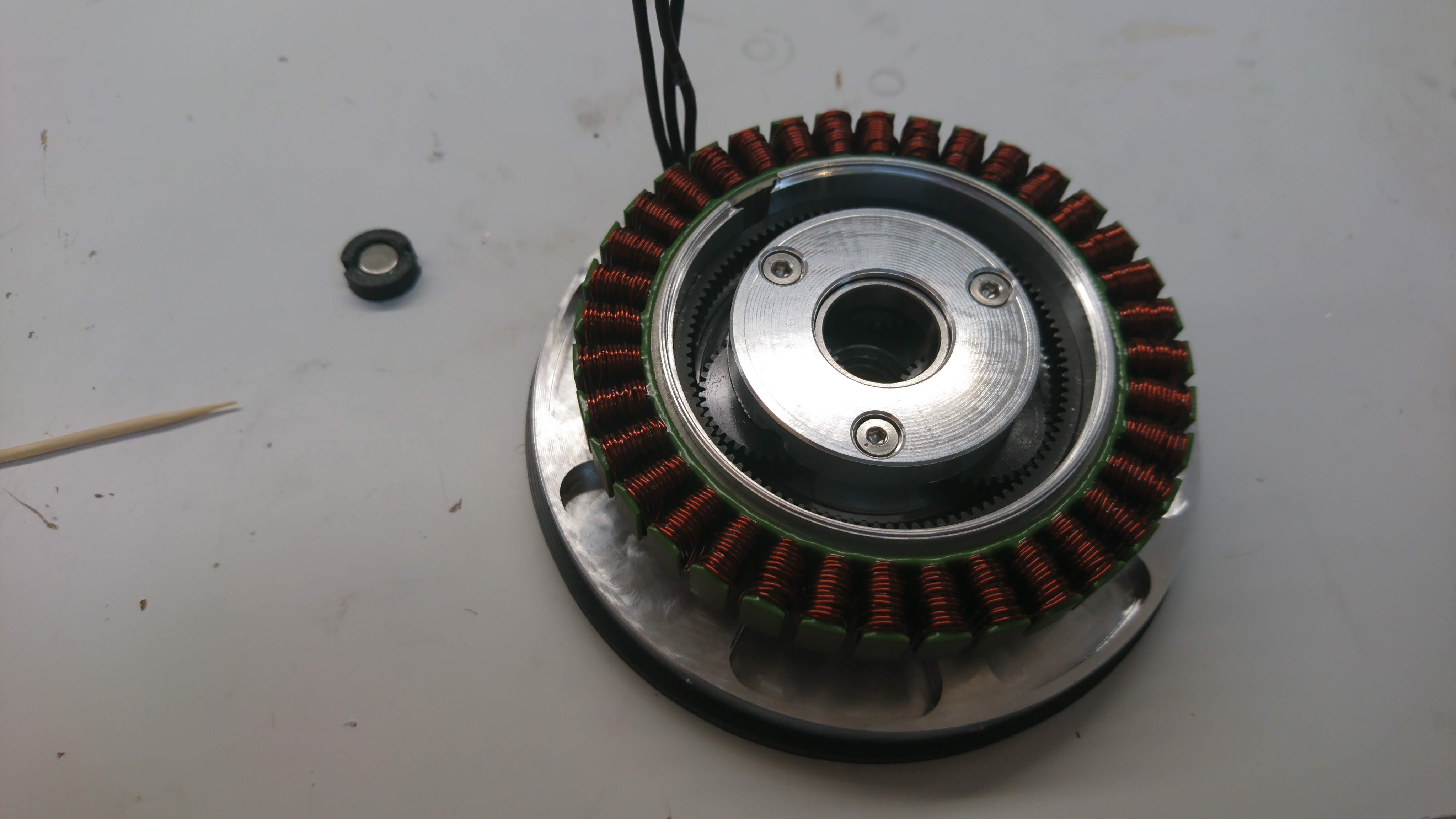
Moteus servo

The first round of gearbox servos went through many revisions to achieve something that was functional.  That said, while functional, they are fragile, and require about a full man day of assembly time per servo.  I’m working to get pre-production volumes of around 100 units for all the components such that no post machining will be required and the servos can just be assembled together.

While I’m at it, I intend on switching everything to metal from 3d printed plastic, and reducing the overall dimensions.  It is likely the mass will increase a little from the current 410g, but I’m hoping that it won’t be that much compared to the increased strength and rigidity.

Junction board / raspberry pi 3 hat / pre-charge board

I intend to rework the architecture behind the power and data distribution internal to the quad A0.  Currently there is a raspberry pi3 hat, which merely powers the raspberry pi and provides an RS485 interface.  Then a “junction board” splits out the RS485 bus into four separate connectors as well as splitting out power to all four legs and housing the IMU.  Finally, a separate “pre-charge” board ensured that the servos can have power applied safely.

I intend on moving all data distribution and the IMU onto the board that mounts on the host computer.  Thus it will have power in, an IMU, and 4 (or maybe more) CAN bus outputs.  Then, a separate power distribution board will include the pre-charge circuit as well as connectors for power for all four legs.  Simultaneously, I plan on adding an actual power switch, so that I don’t have to keep pulling the battery in and out to cut power.

Chassis

The quad A0 chassis is a single monolithic 3D printed block.  Actually attaching legs to this is nigh impossible.  It takes a long time, and not all of the joining screws can actually be used because of interference with other pieces.  Also, using the Ryobi style batteries results in a lot of dead space due to the mounting stud.  I am planning on switching this chassis to be printed in multiple components that are assembled together with screws and threaded inserts and switch to a battery form factor that is more compact.

That should also allow for mounting the primary computer inside the chassis, and still leave enough room for a bigger computer, like an NVIDIA Jetson nano.

Legs

I’ve already had one failure in the current iteration of the leg that indicates some redesign is necessary.  Also, the two primary brackets that connect the shoulder to the upper leg, and upper leg to lower leg should be made from aluminum instead of being 3d printed.  Those brackets had to be really big and printed in odd orientations in order to be strong enough, and they could be a lot lighter, more convenient, and more cost effective in metal.

Looking forward

Thanks for all of your positive feedback so far, and I look forward to more exciting times executing these plans!

Quadruped robots: One year in!

While I’ve been working to some degree on quadrupedal robots for the last 5 years, it has been just about 1 year since I kicked up my effort a notch, with my post about improved actuators for SMMB.  I figured it was a good time now to produce a video summarizing what I’ve gotten done over the last year:

Concurrently, I’ve posted a “state of the project” text update on hackaday.io, just to get a wider readership.  If you’ve been reading here all along, there won’t be anything terribly new there, but it is a decent summary of where I stand.

Oh, and I’ve decided to give the robot a more memorable name for now.  The “mjbots quad A0”!  Yeah, I’m no marketing whiz, but it will suffice.

Coming up next, is a brief roadmap of where I plan on focusing my efforts in the next 3 to 6 months.


Revisiting machining the sun gear holder

My very first sun gear holder I machined myself was something of an artistic feat.  Each operation was re-run many times, and as a result the part was largely a one-off.  The final part properties were not really indicative of the final program.  My next step in my learning adventure was to up my Pocket NC game and get to a single reproducible program that would emit a part that I could use, then be able to run it over and over again.

The biggest problem I had in making this happen was pull out problems that manifested intermittently, but persistently.  When machining the part in a single operation, the mill needed to be able to reach all the way to, and slightly past the center of rotation of the B axis of the machine.  With the Z travel of the Pocket NC, that means that you need a stickout of almost 27mm or sometimes even more.  Standard length tools can kind of do that, but they don’t result in much of the shank being in the collet.  All my testing with them resulted in occasional pull out at some point during the hour or two of machining.

I tried getting a Kyocera 2 inch endmill 2 flute end mill, which has a minimum stickout of about 34mm.  To run it without mind numbing chatter required dialing the feeds and speeds so far back that the part would take twice as long to complete.  That hardly seemed worth it.

Next, I stepped back and decided to try a 2 operation approach using the Sherline 4 jaw chuck.  This has the advantage that the part is always kept well within the Z travel of the mill, so that standard length end mills can be used, but the disadvantage that you have to manually flip the part over and try to keep things registered.  I don’t have great, or really any, metrology that would allow me to measure the resulting concentricity errors so I was really trying to avoid using this approach, however, I was kind of at a loss at this point so decided to give it a go.

For this configuration, I used a 1.5″ round stock cut to approximately 1″ long.  The first operation used a Datron 3mm end mill to do nearly everything on the back side, with a final chamfer mill pass to break the edges.  The second operation used a Datron 2mm end mill to do everything there, with the chamfer mill once again to do the countersinks and break edges.

The parts that come off here are usable, and about what I expected to achieve without heroics in terms of final accuracy from a Pocket NC.  All the diameters and dimensions are around at most a thousandth off from what I intended.  The walls aren’t as vertical as I would like, but they are serviceable.

Final part
Final part

dsc_1534
My various experiments, single op in back, multi-op in the front

Granted, I probably won’t be using these parts for much of anything going forward, but it was a great learning experience in making the Pocket NC do what I wanted.  Next in this adventure is probably machining a planet input, which I forsee continuing to use in future iterations of the gearbox.