Standard time
While I despise switching between daylight savings time and standard time, the switch does bring new timing to regular routines that can suprise you!

While I despise switching between daylight savings time and standard time, the switch does bring new timing to regular routines that can suprise you!
For many years https://jpieper.com was a home for my personal writings and projects. As some of those projects turned into mjbots, the line became pretty blurry. To try and shore up some personal work/life balance, I’ve moved nearly all posts that in hindsight were “mjbots” related over to https://blog.mjbots.com and removed them from here.
There should be redirects for all old articles and the URL scheme should be identical such that nearly all old links should continue to work. If you were subscribed via email, you should have received one final message, as this new site no longer supports direct email notification. If you were subscribed by RSS, you now get to pick if you want to update your feed to point to https://blog.mjbots.com/index.xml or include it in addition to this one.
Who knows, maybe I’ll have a fun personal project to write about again!
Blinking lights is something that I guess I’ve been enamored with for a while - see 2001 dorm (with awesome work from Brad on visualizations), 2007 bike, and 2015 trumpet. When I got a last minute opportunity to play sousaphone at this year’s HONK fest with Brassterisk I figured I needed something to dress up my otherwise rather drab horn.
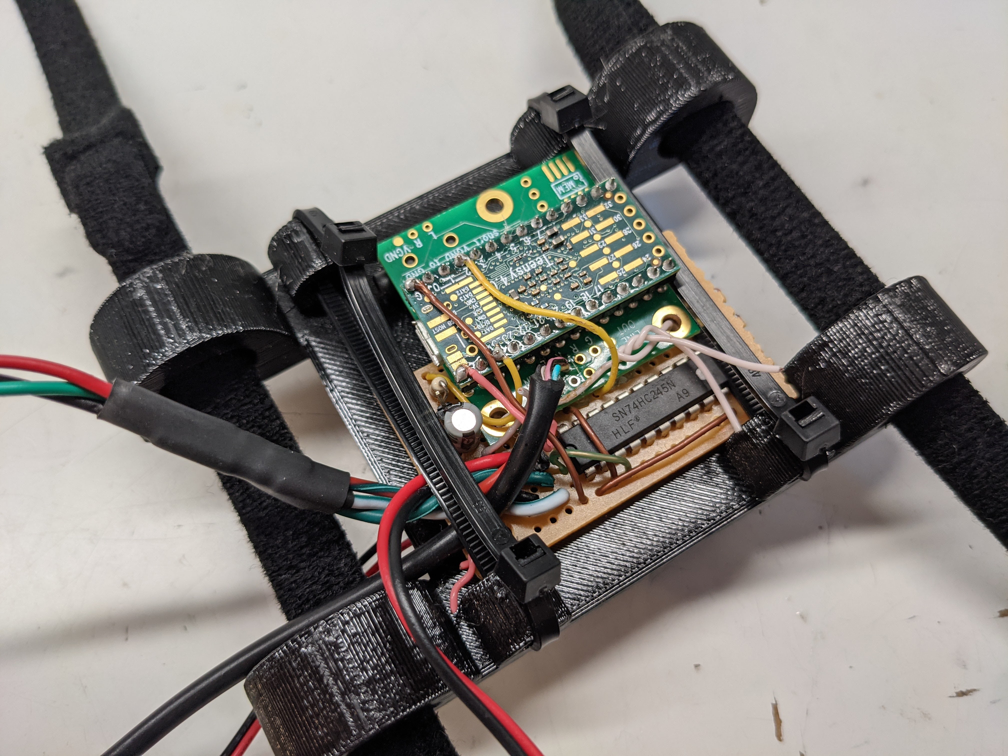
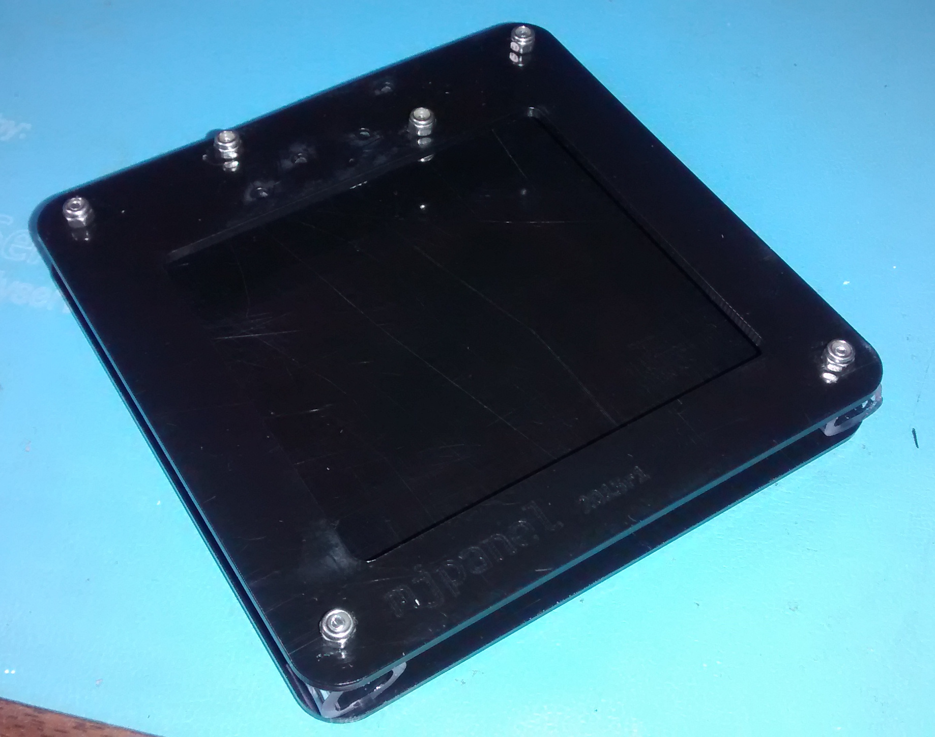
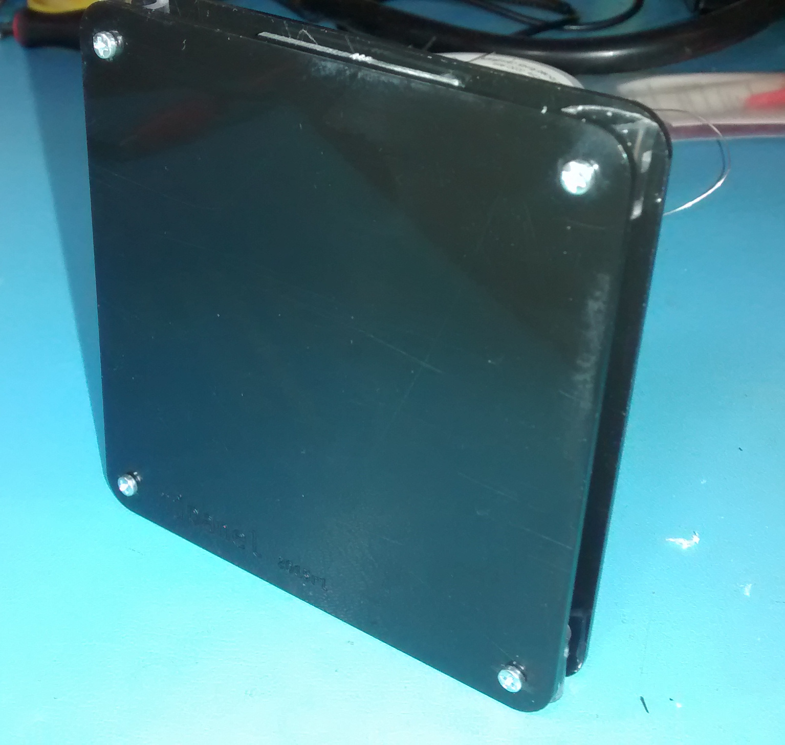
The "control board"
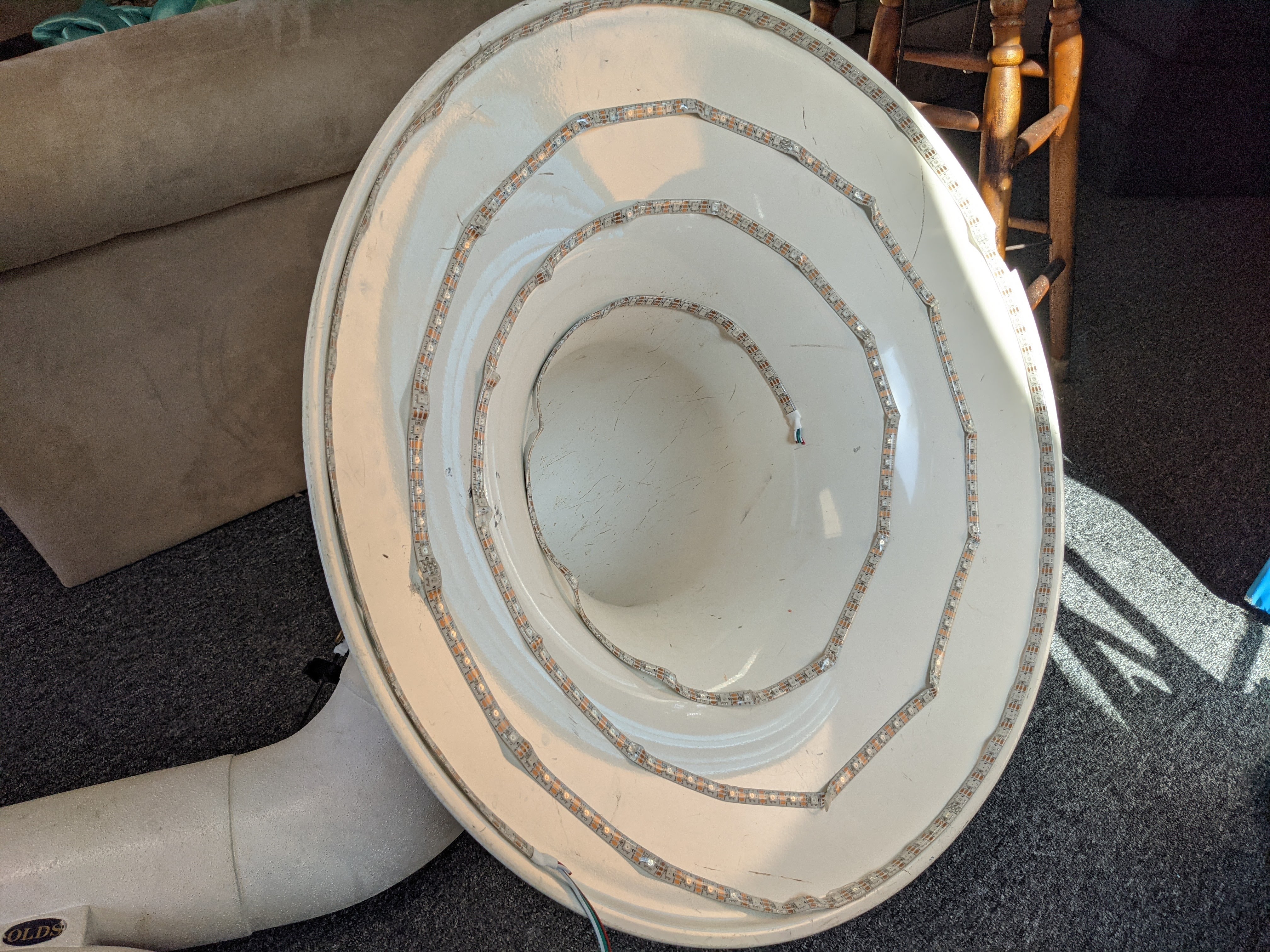
Light installation on bell
It is just a Teensy 4.0 I had lying around, together with an audio board, a basic lav mic, and a spare 74XX245 from my grab bag held together with hot glue and proto wire. It drives a cheapo 300 LED RGB strip that is VHB’d to the bell. I think the LEDs will only last a few more transport sessions, but with any luck I’ll make a slightly more polished revision with better longevity in the not too distant future.
Behold, lights:
If this space is looking stale, that’s because it is! I am traveling until the middle of August. Look forward to more robot and Pocket NC updates then!
In the meantime, check out these cool posts from the last year:
For many years now on and off I’ve played in the programming contest associated with the International Conference on Function Programming. Each time it has been fun, exhilarating, and definitely humbling! www.icfpcontest.org
This year, the competition runs from Friday June 21st through Monday June 24th. Once again we’ll be competing as “Side Effects May Include…". Look for us on the leaderboard and cheer on!
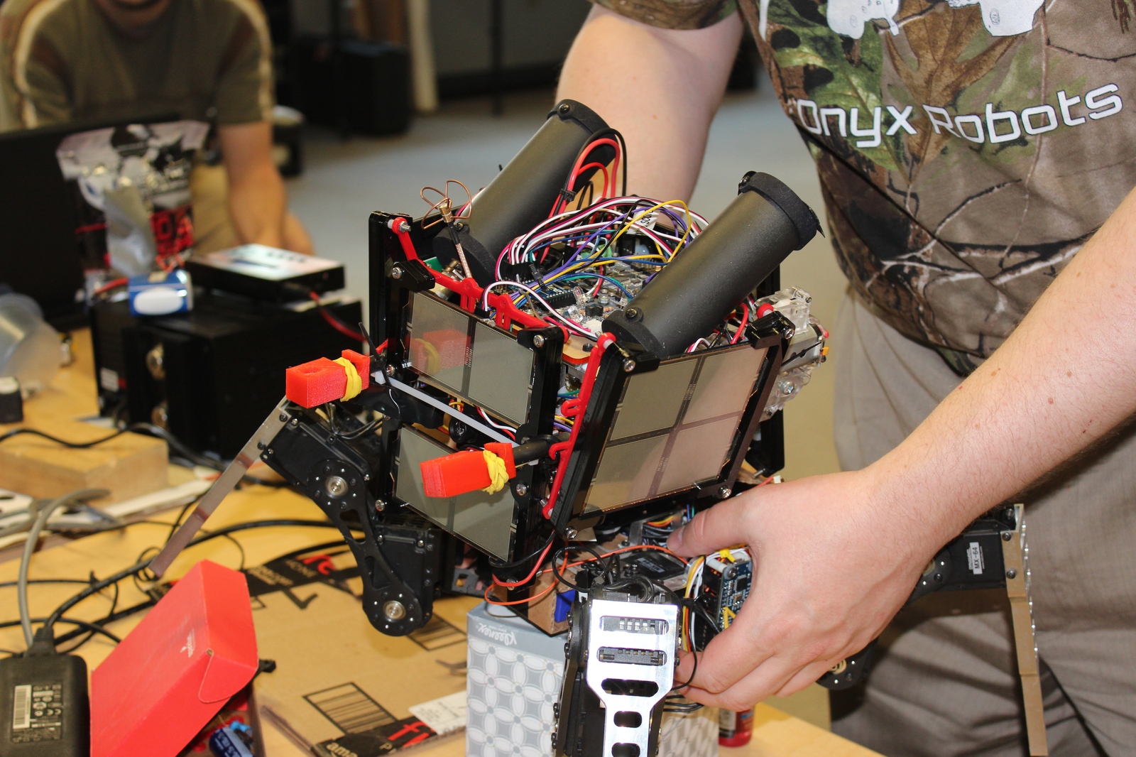
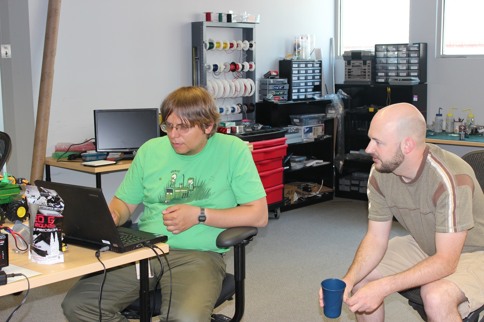
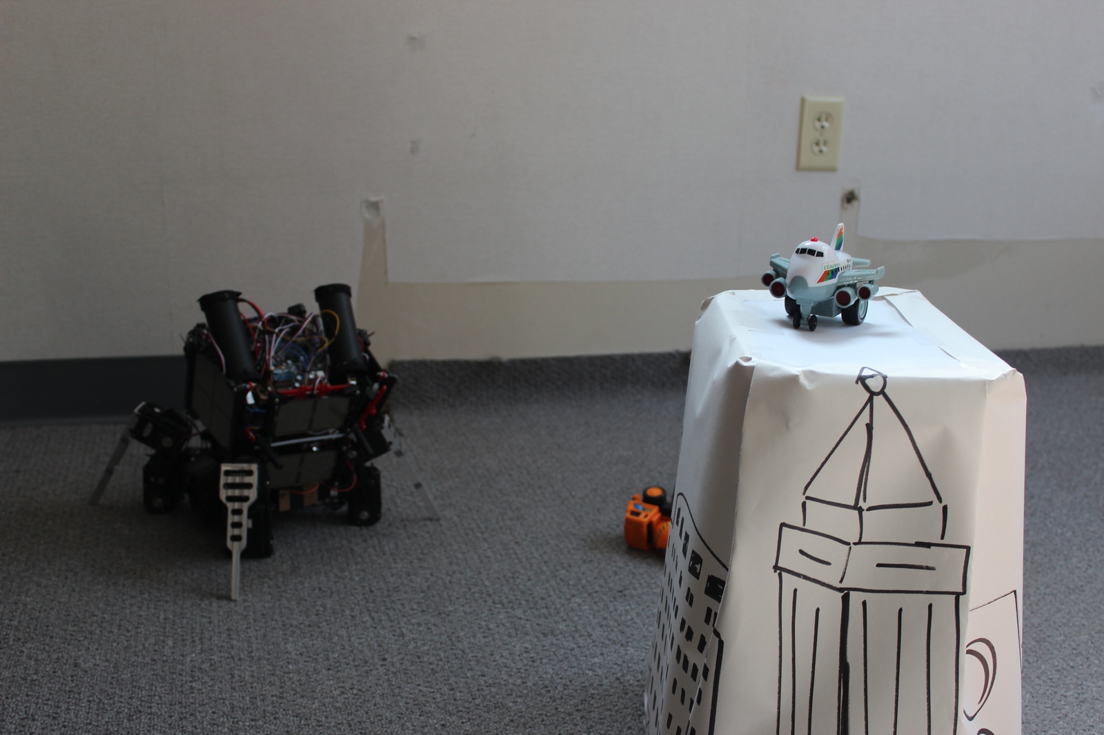
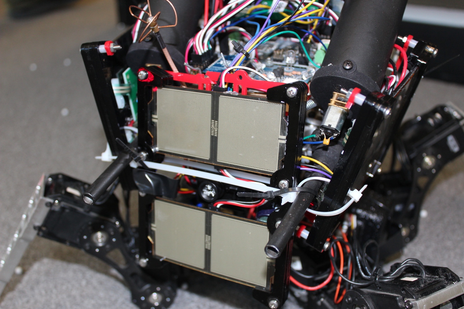
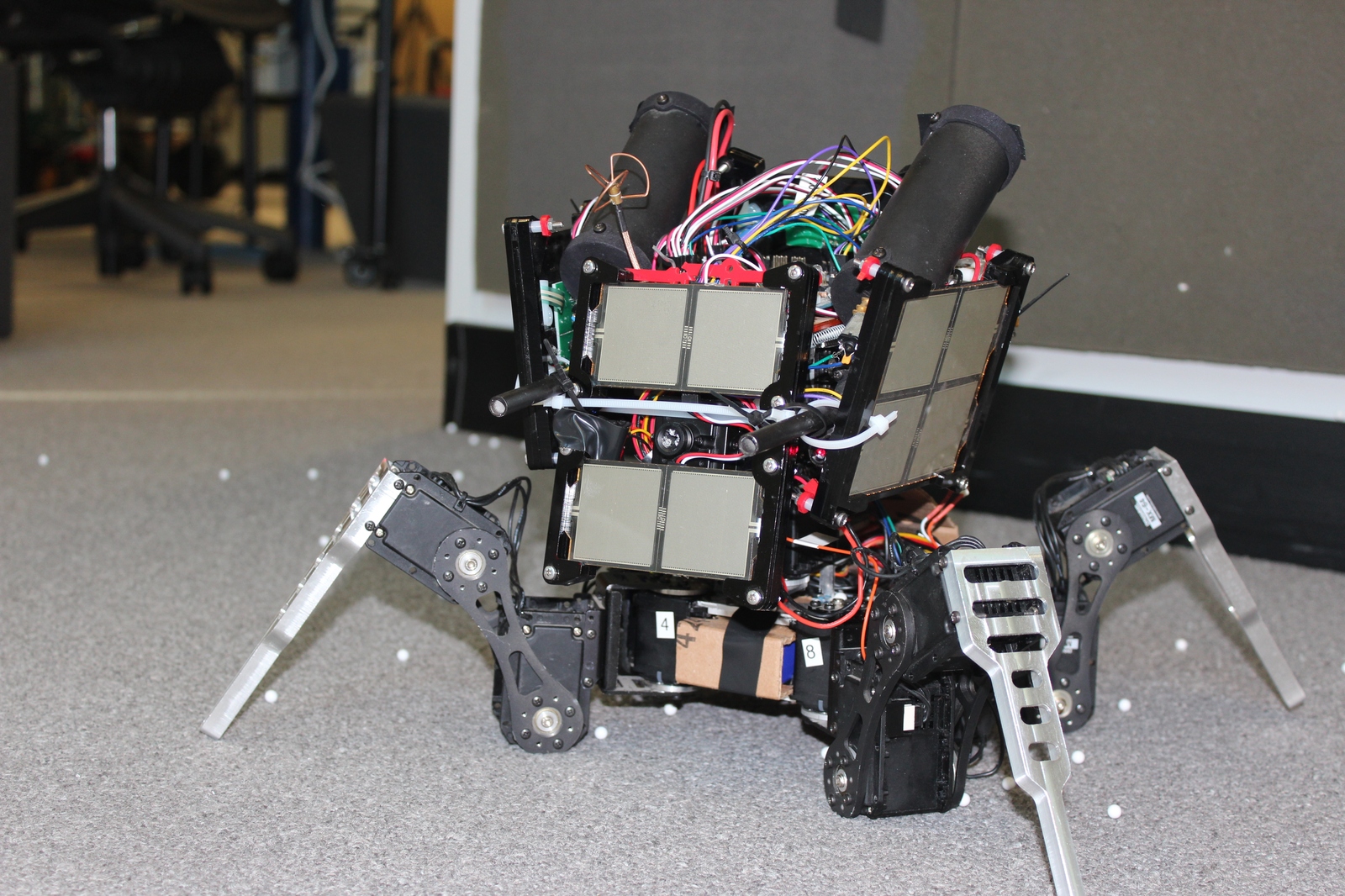
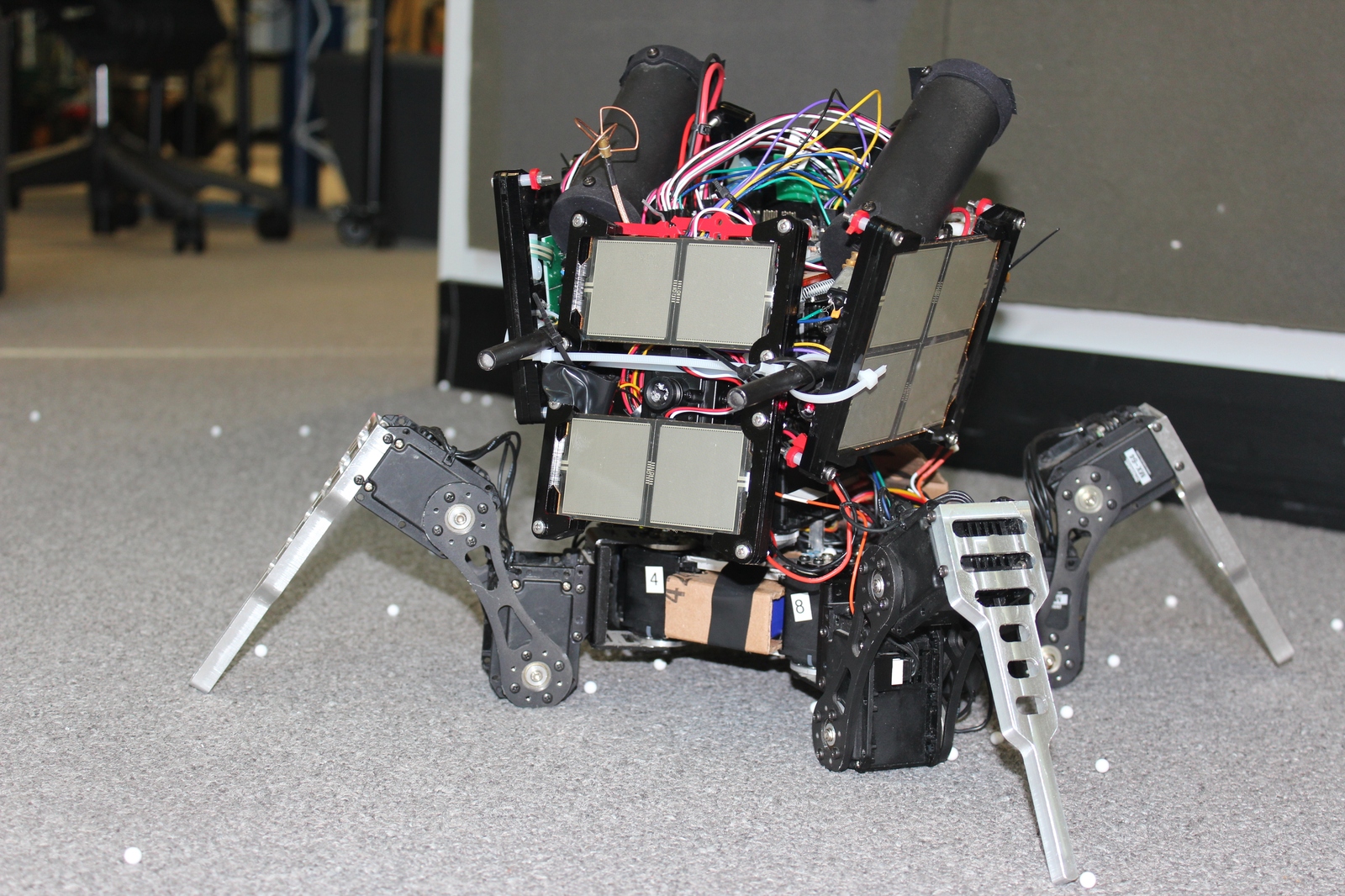
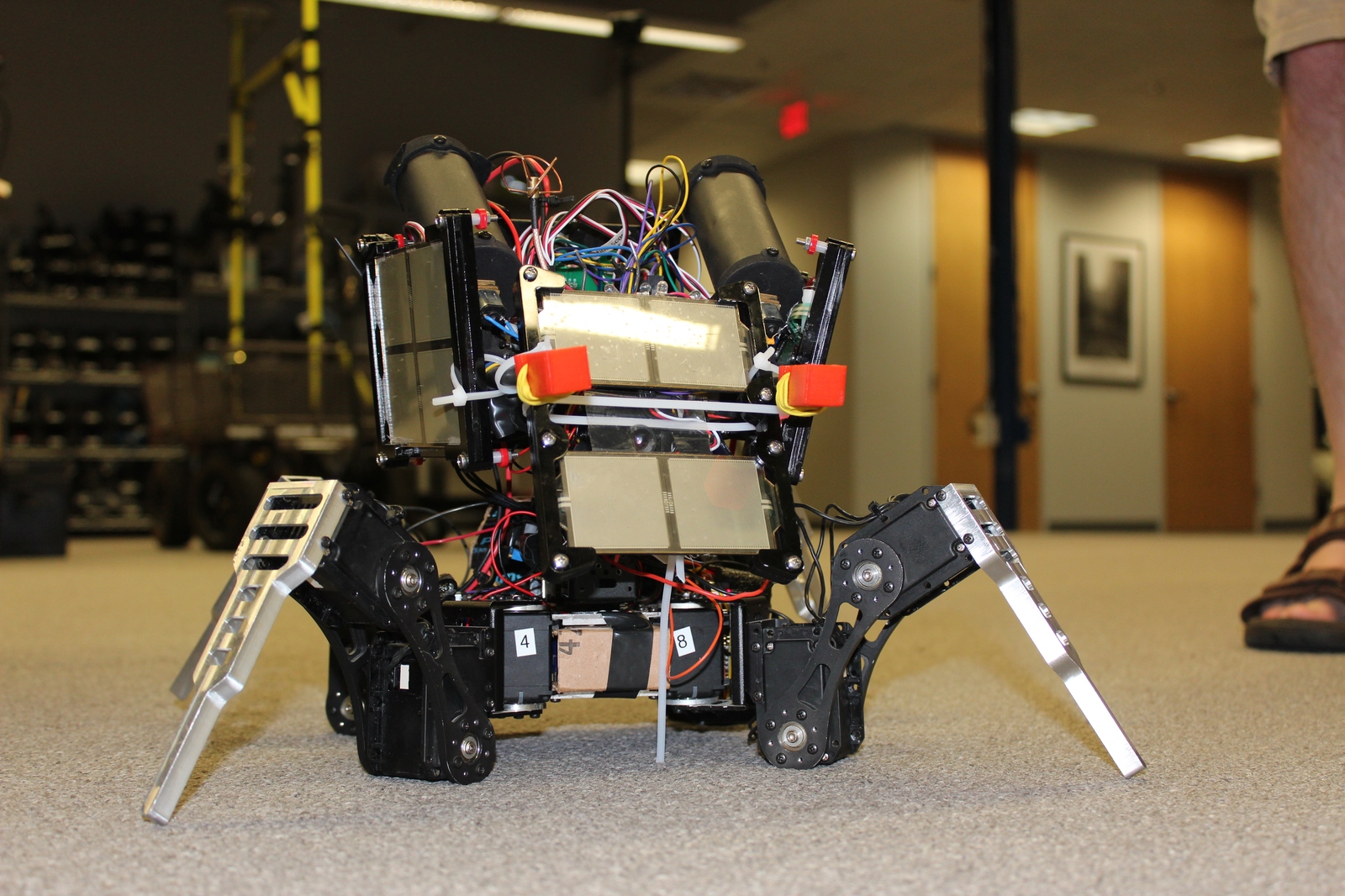
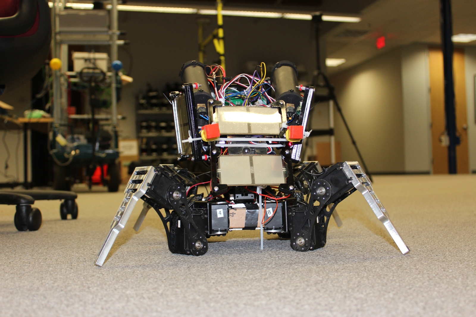
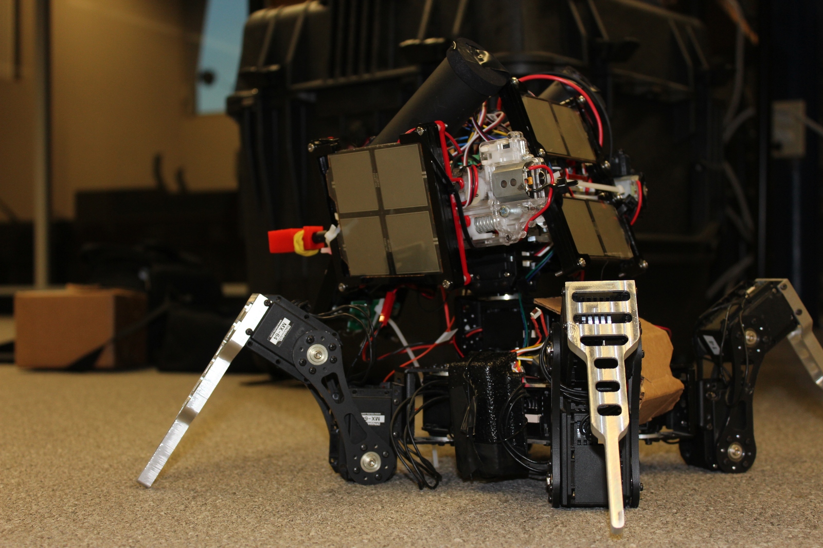
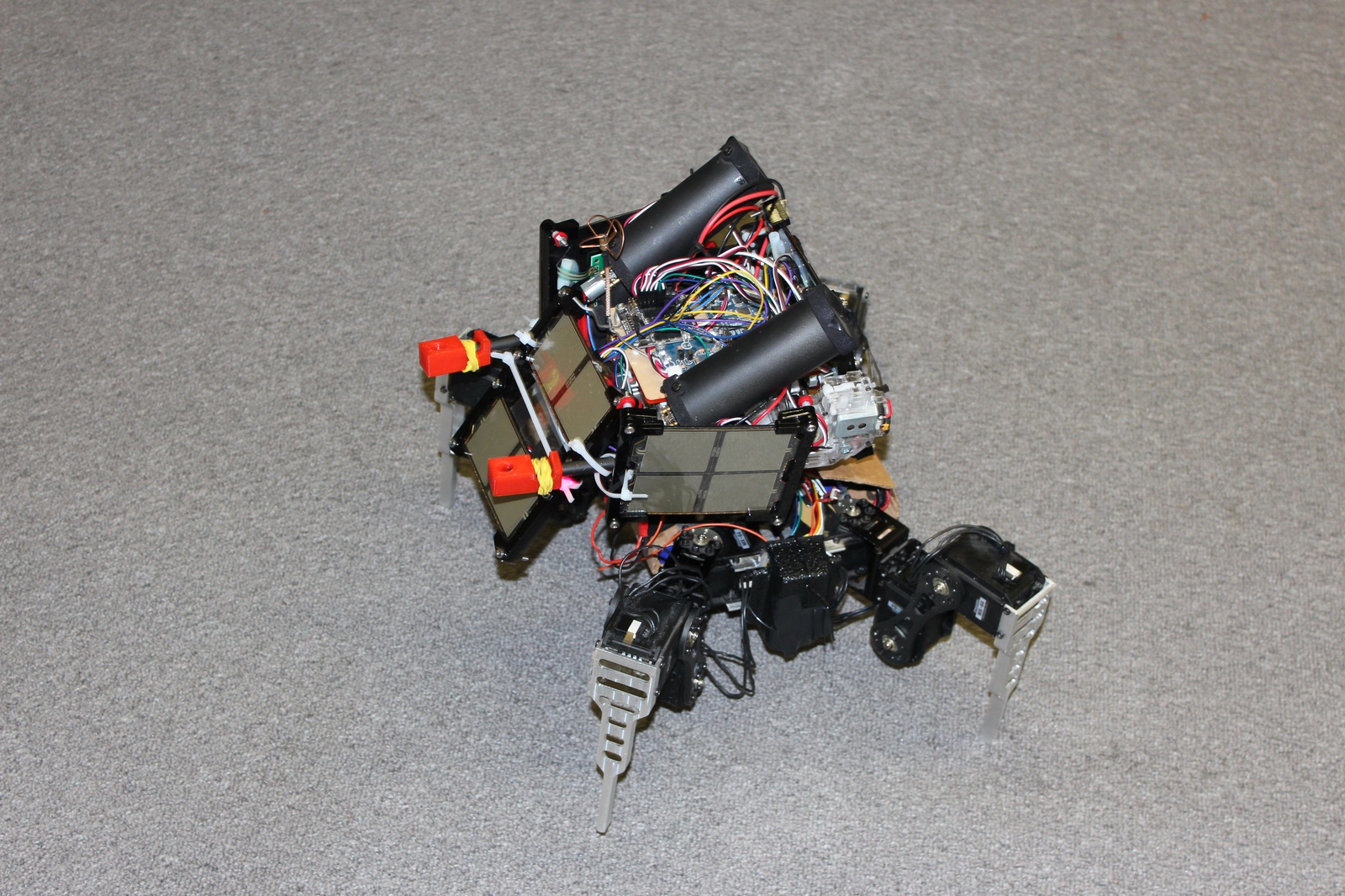
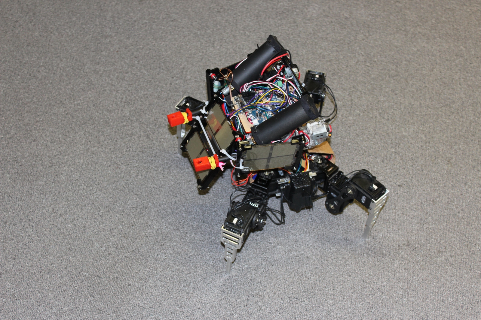
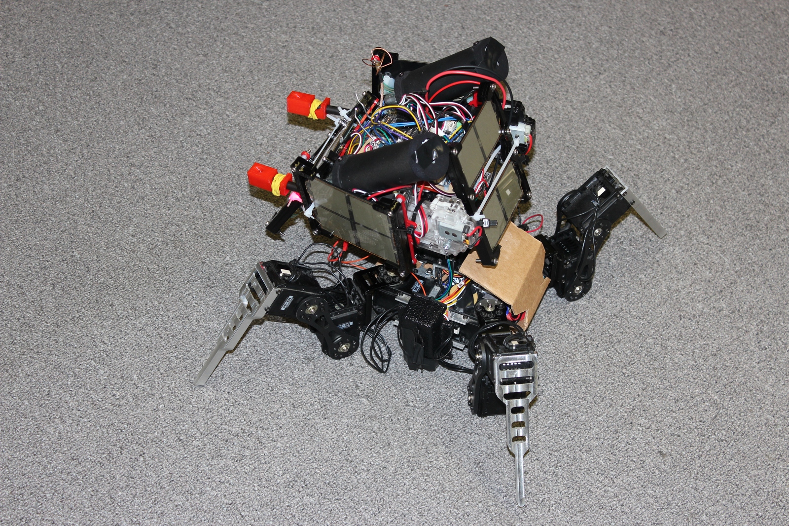
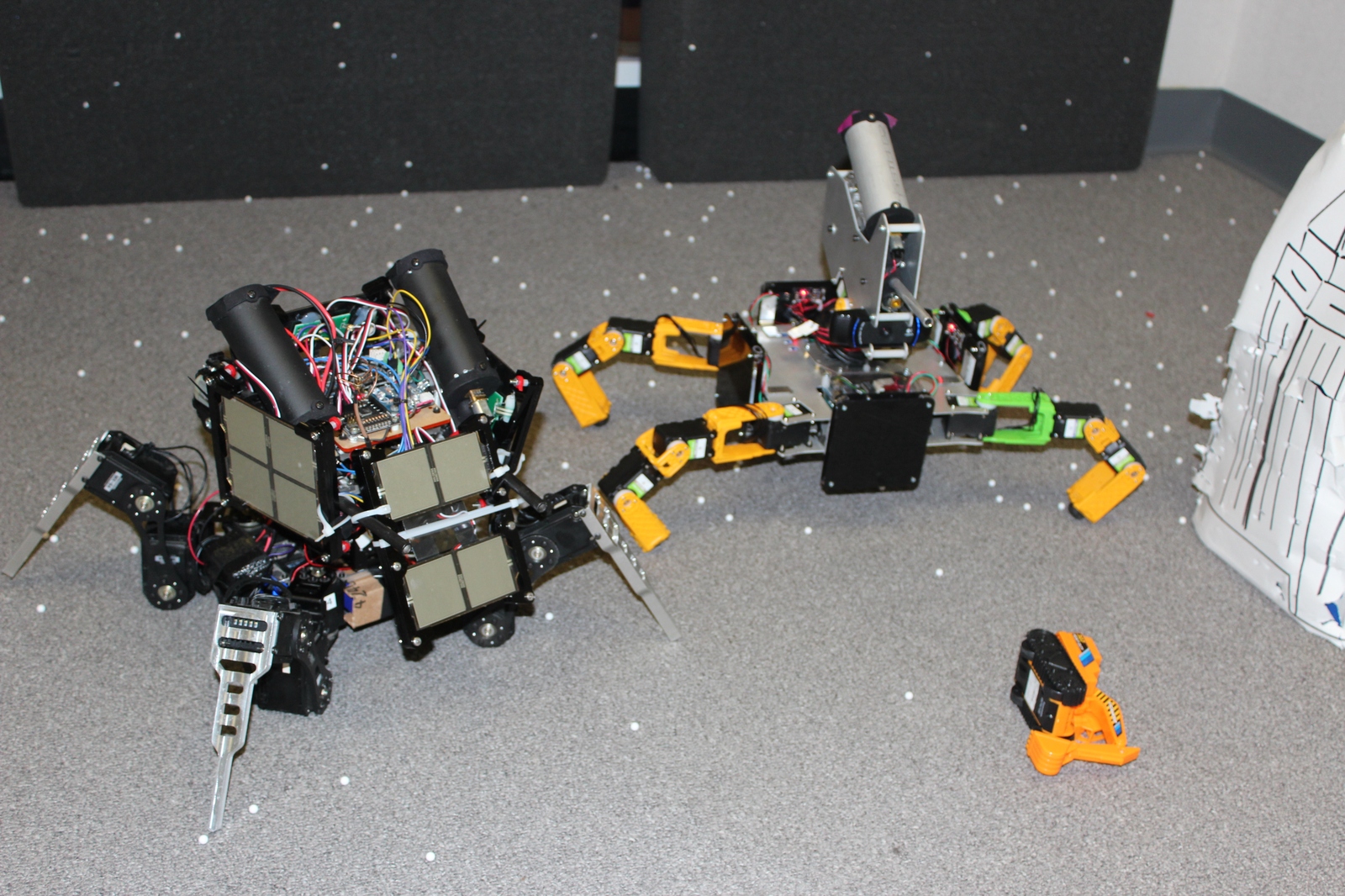
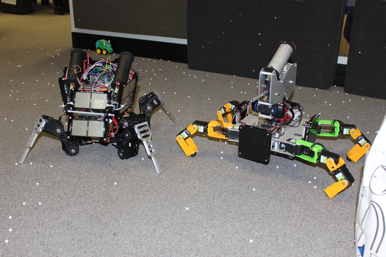
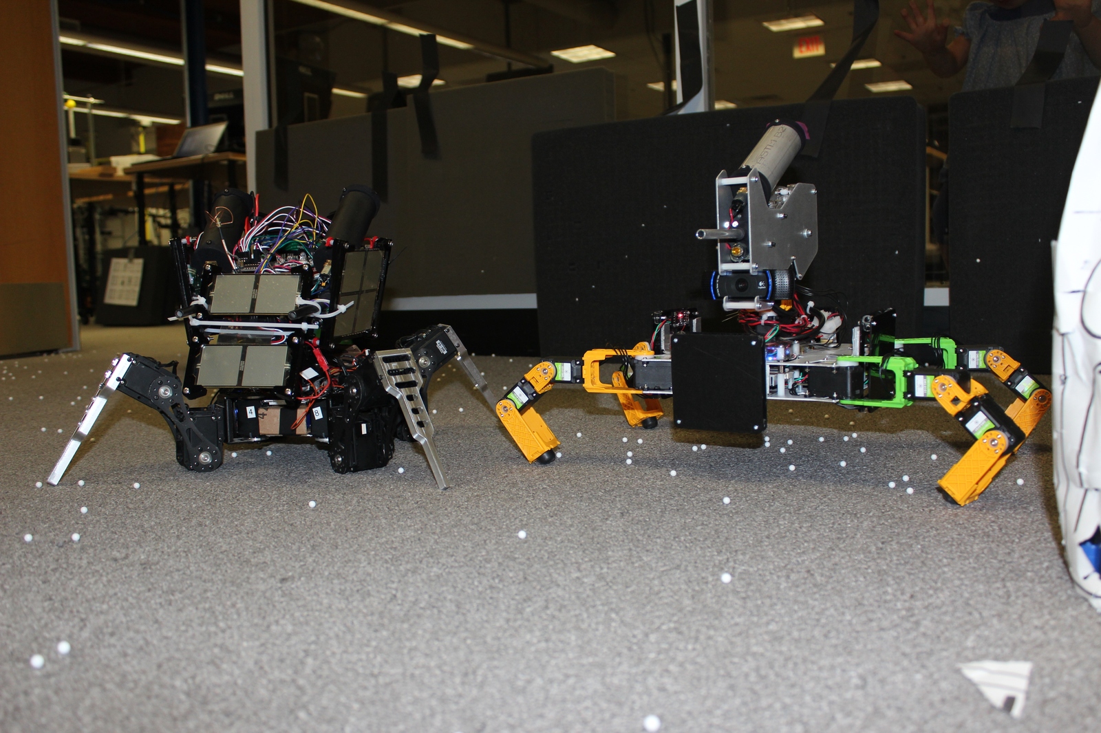
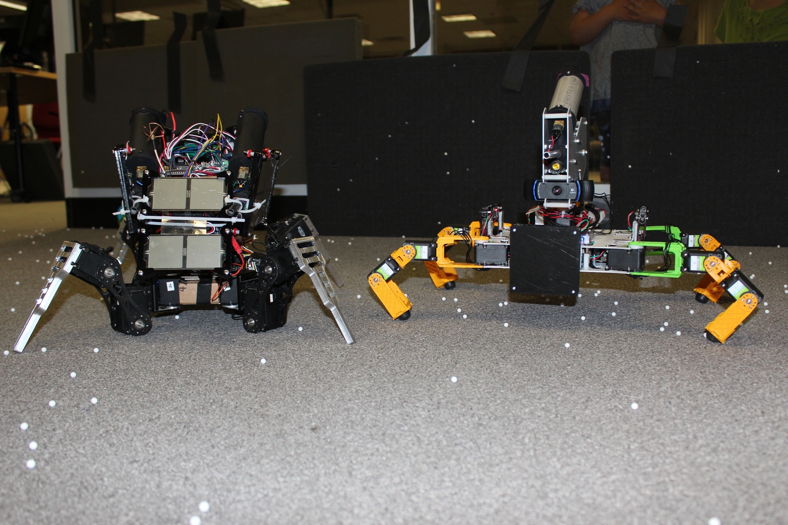
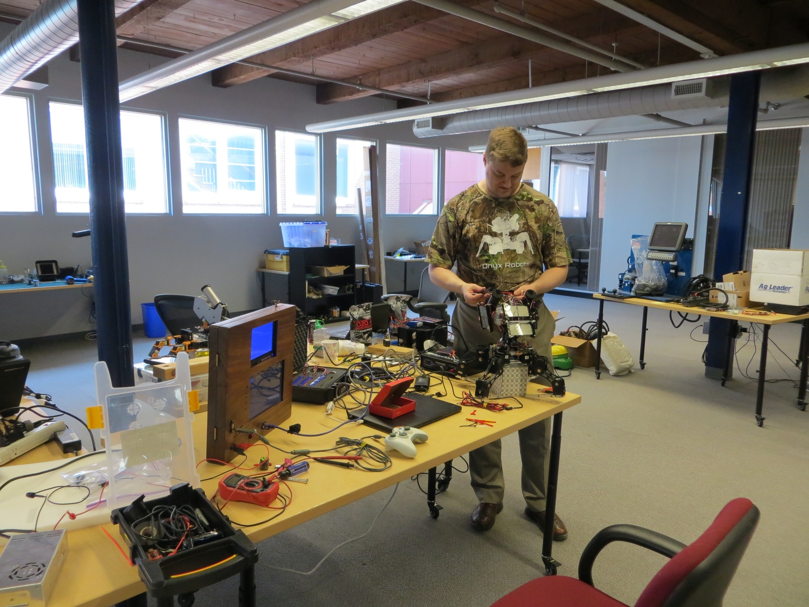
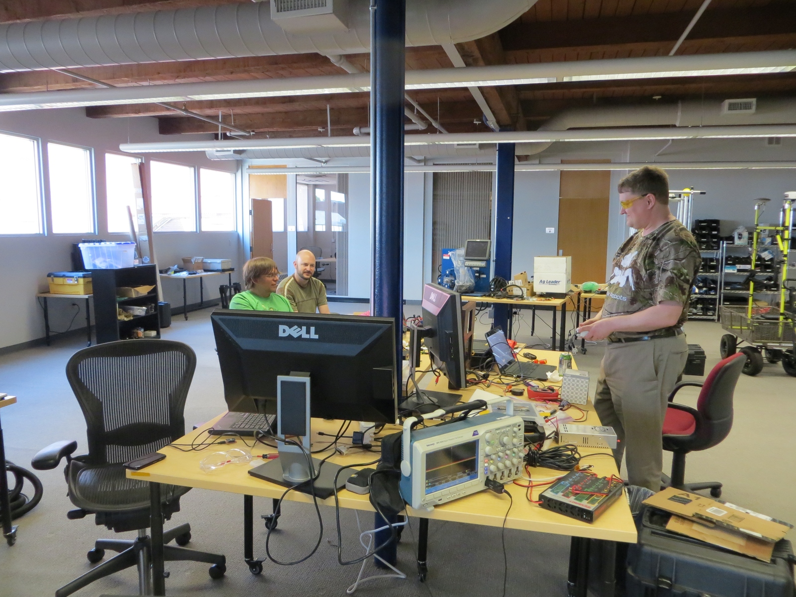
Earlier in April we took Super Mega Microbot out to California to compete in Mech Warfare during Robogames 2016. Thanks to the R-TEAM organizers who made the event happen this year. We were really excited, and the event as a whole went off really well! There were a lot of functional mechs attending, and many fights that were exciting to watch.
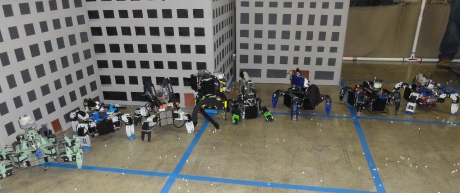
Most of the mechs which competed
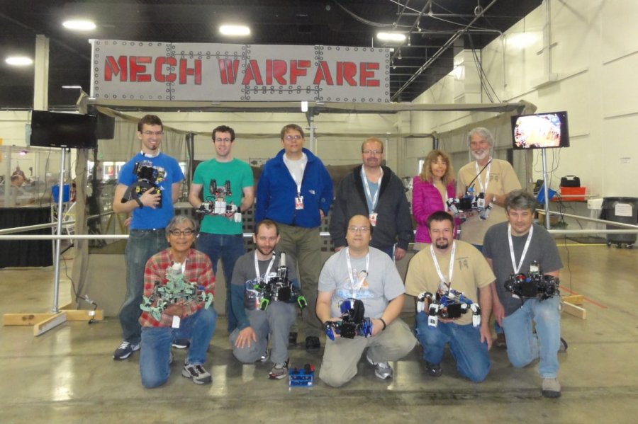
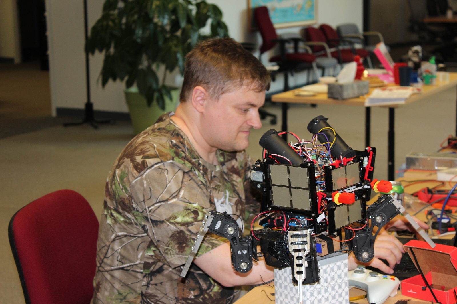
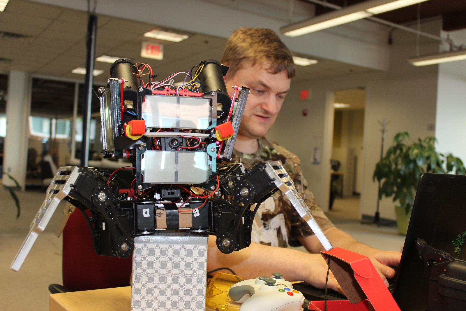
And their human operators
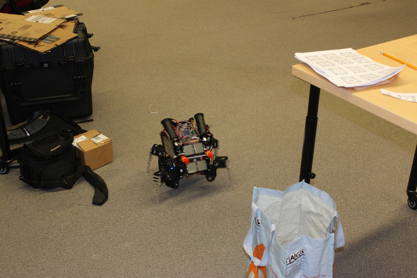
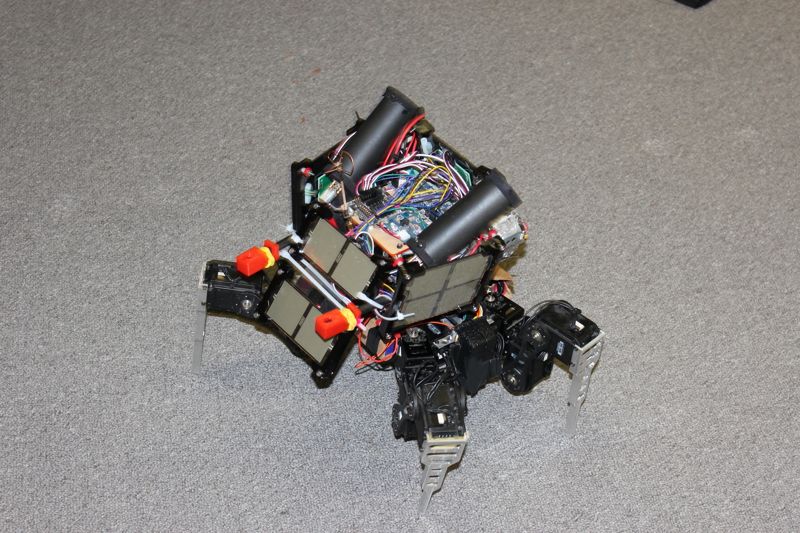
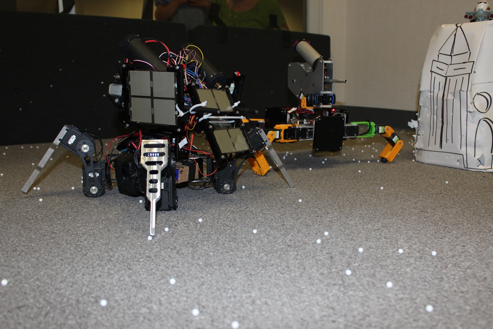
We managed to play 5 official matches, in the double elimination tournament, finishing in 3rd place overall. When it worked, SMMB worked really well. Our first loss was a very close battle, the score keeping system had us winning by 2 and the judges had us losing by 2. (The scoring system wasn’t super reliable, so there were human judges calling hits). Our second loss was caused when the odroid’s USB bus on SMMB stopped working mid-match, causing us to lose camera and wifi.
Since our last matches, we tried to improve a number of things, while some worked, not all of them are entirely successful yet:
Thanks to Kevin from R-TEAM, we managed to capture overhead video of all our matches, and have the video as seen on our operator console for each official match as well.
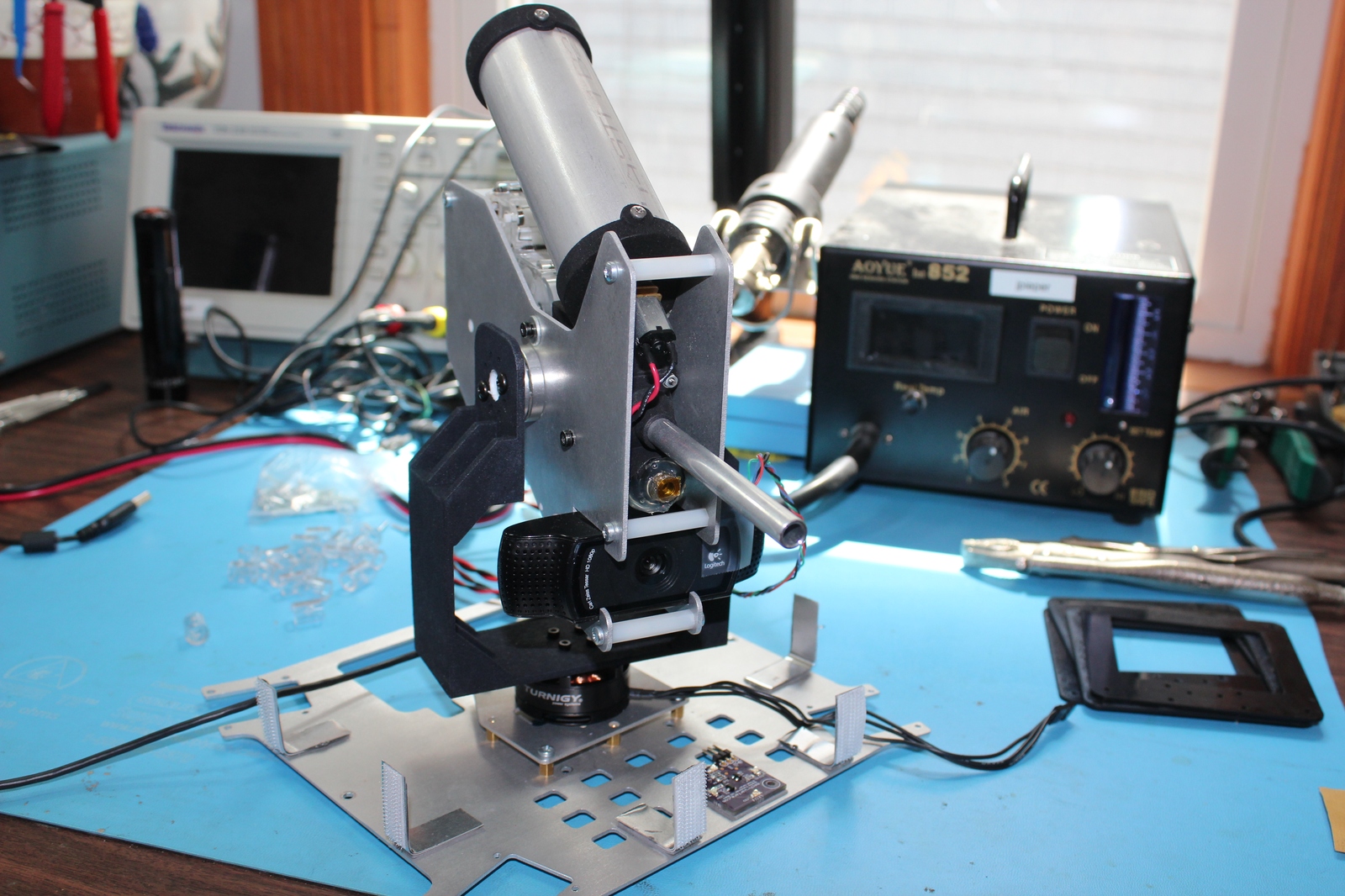
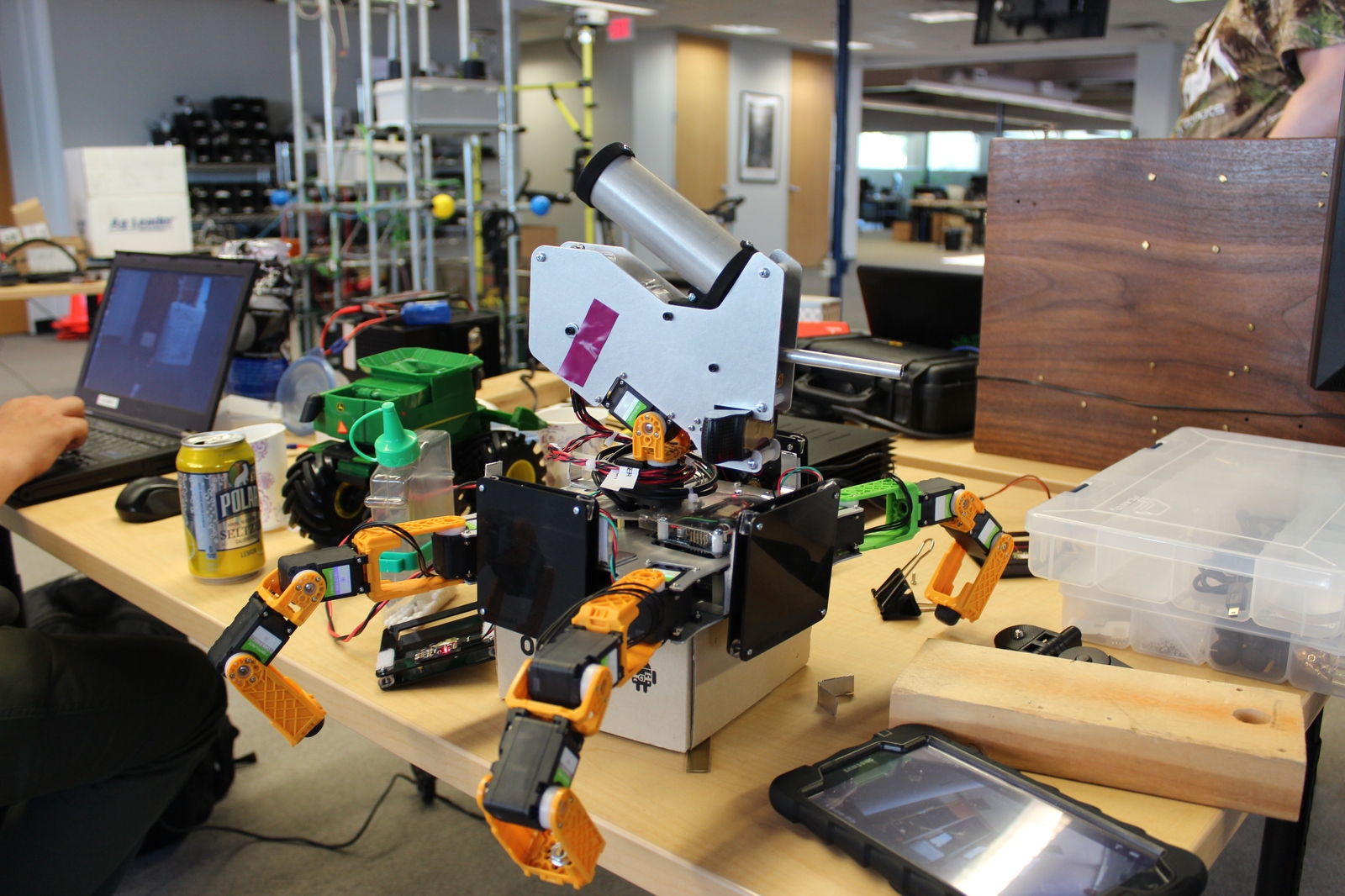
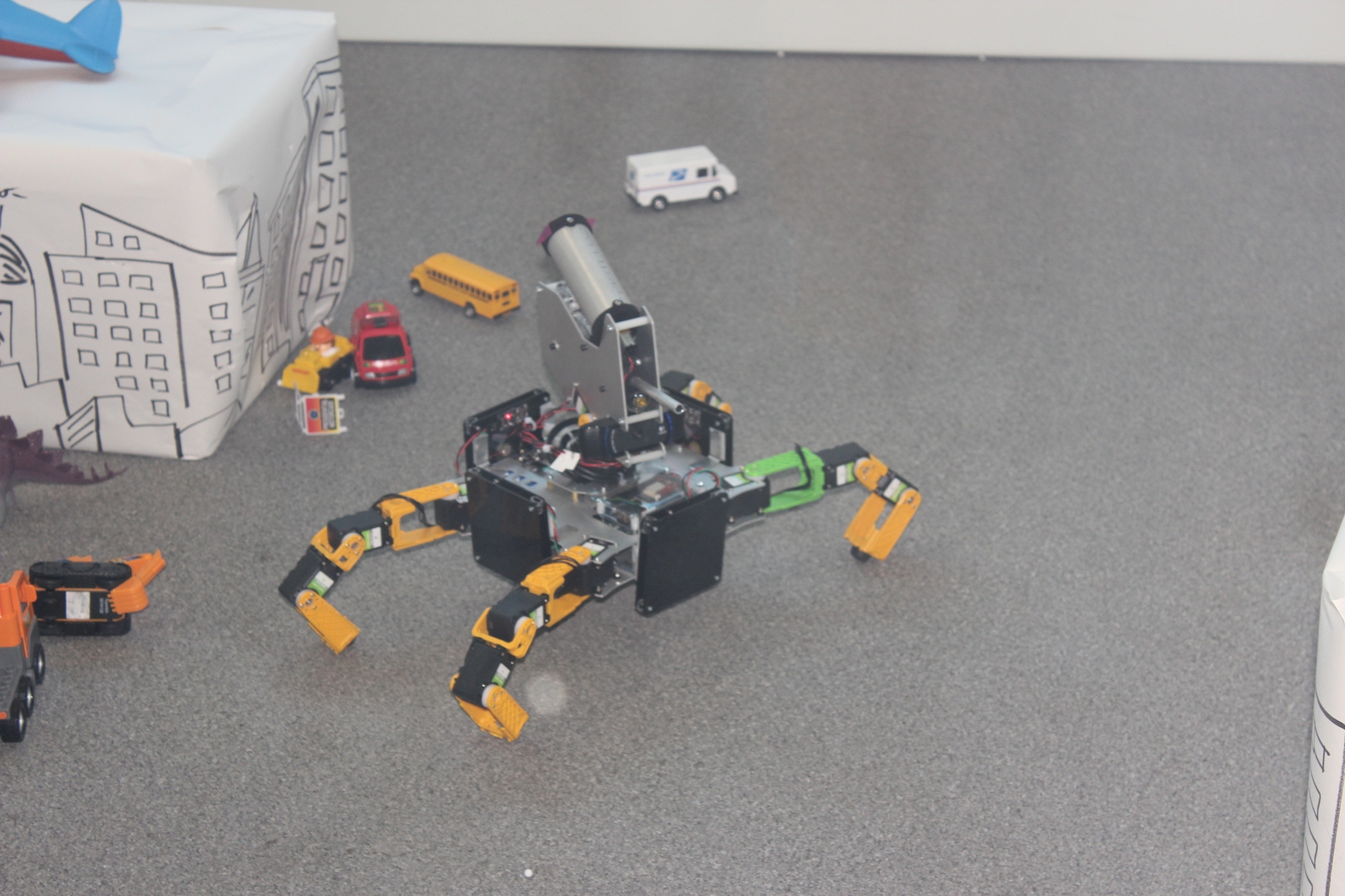
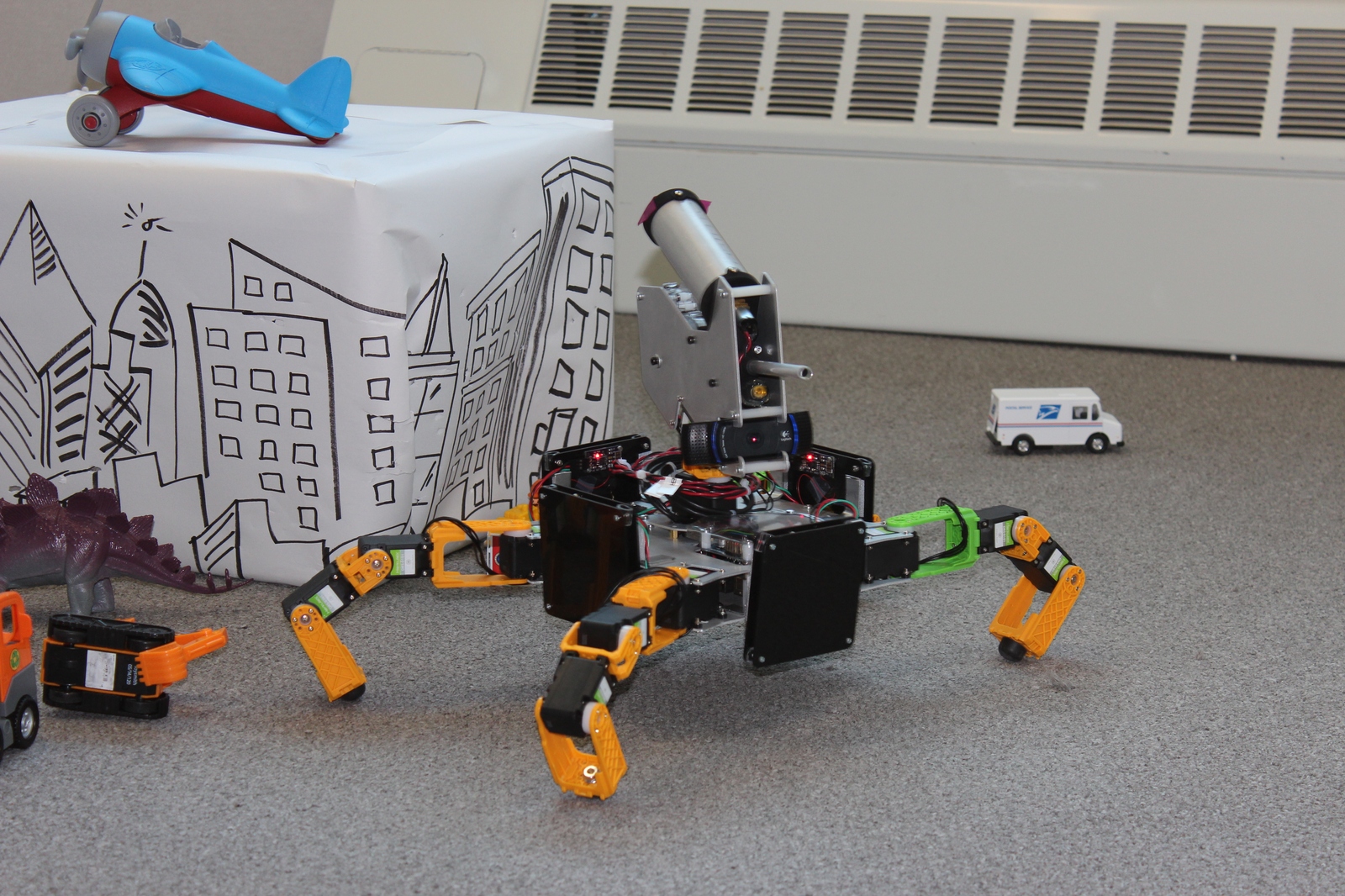
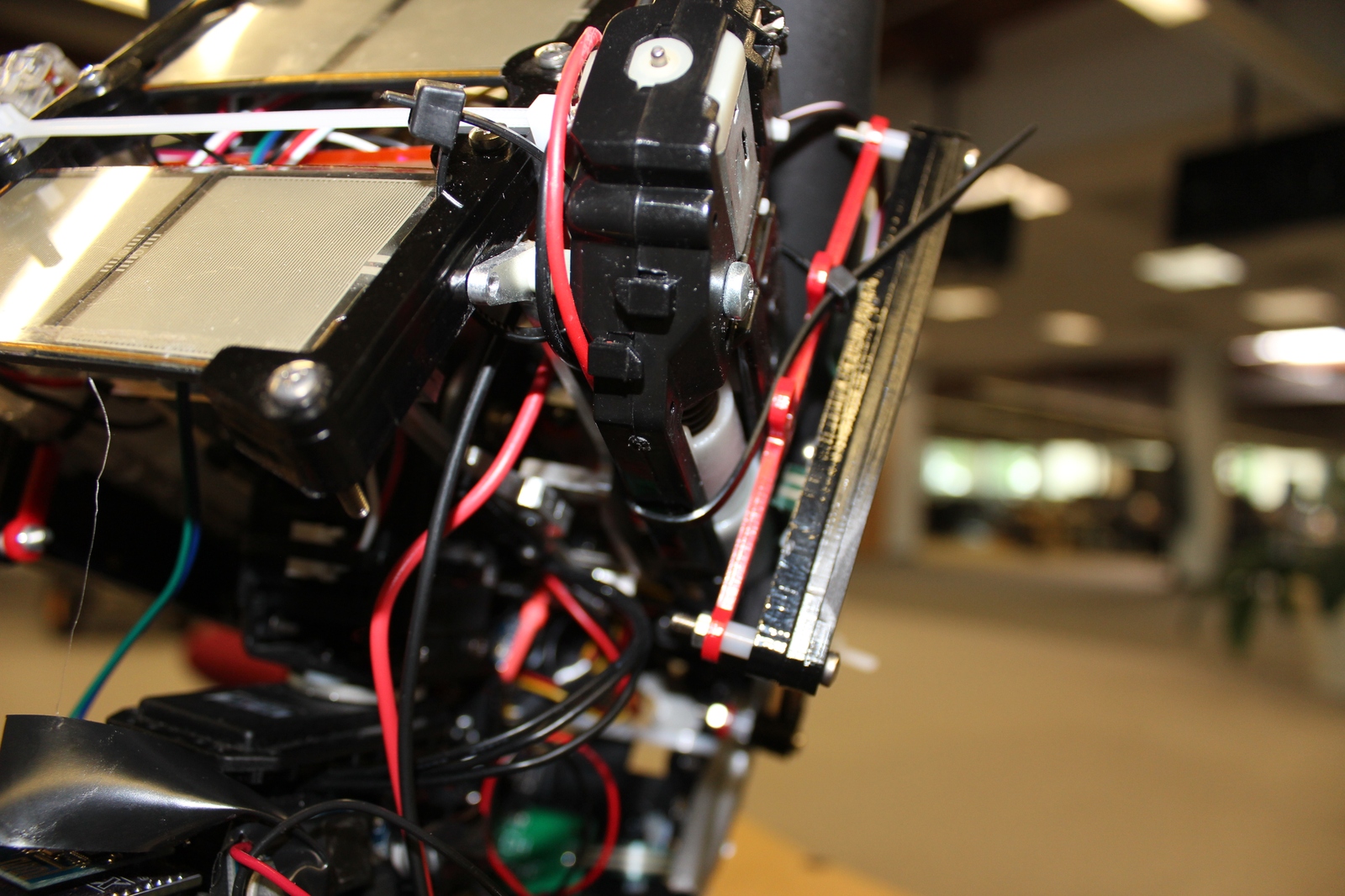
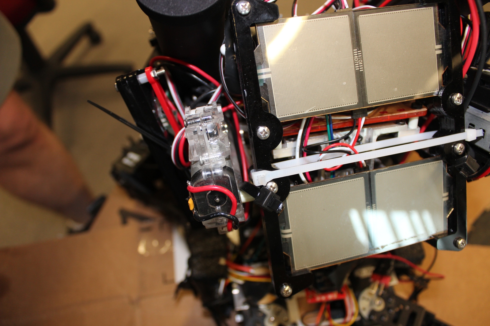
Well, that took longer than I expected! I last showed some progress on a gimbal stabilized turret for Mech Warfare competitions more than six months ago. Due to some unexpected technical difficulties, it took much longer to complete than I had hoped, but the (close to) end result is here!
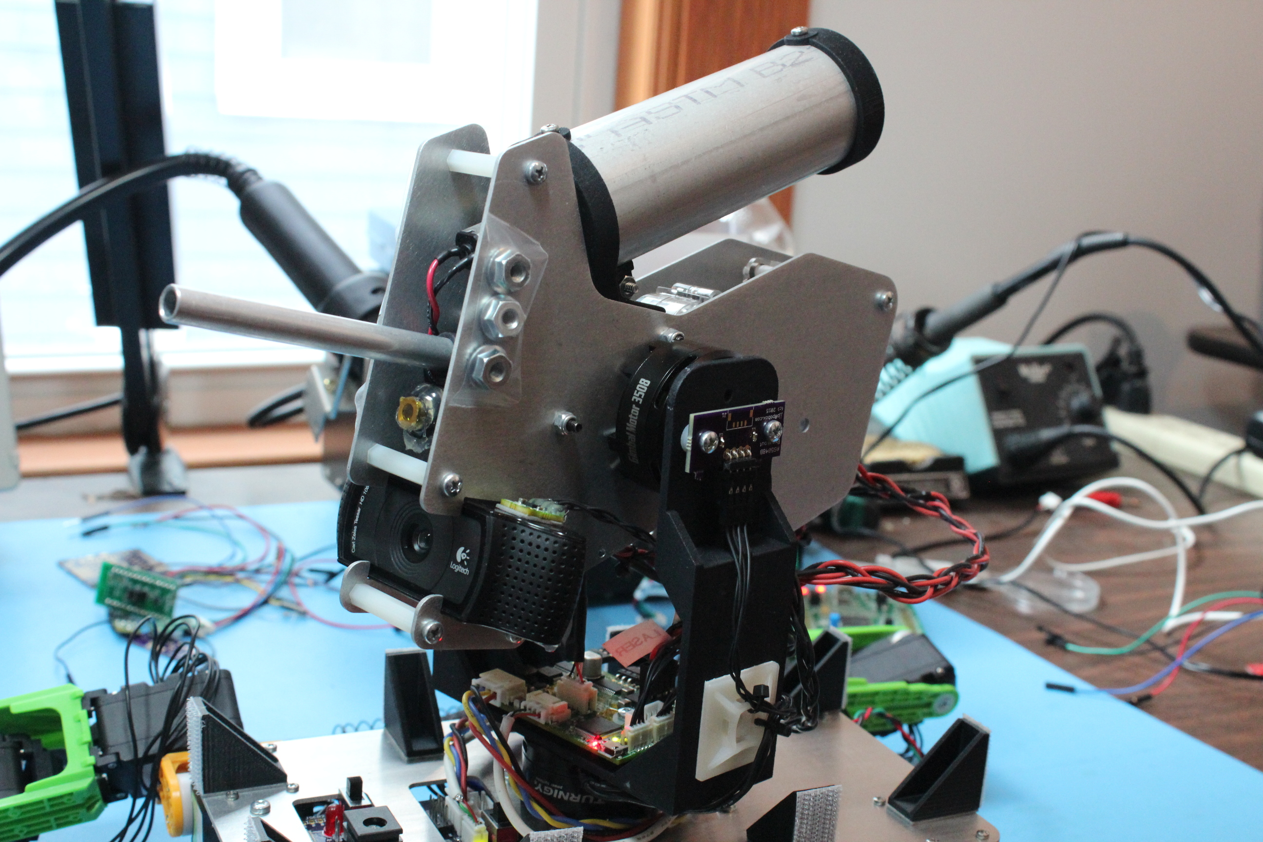
Complete gimbal mounted turret
Here’s a quick feature list:
You can see the turret’s basic operations in a quick video here:
The design is driven by the bill of materials selection. The primary components of the gimbal are as follows:
This gimbal design contains three custom boards, a breakout board for the BMI160 IMU, a breakout board for the AS5048B magnetic encoder sensor, and the primary board which contains the rest of the logic.
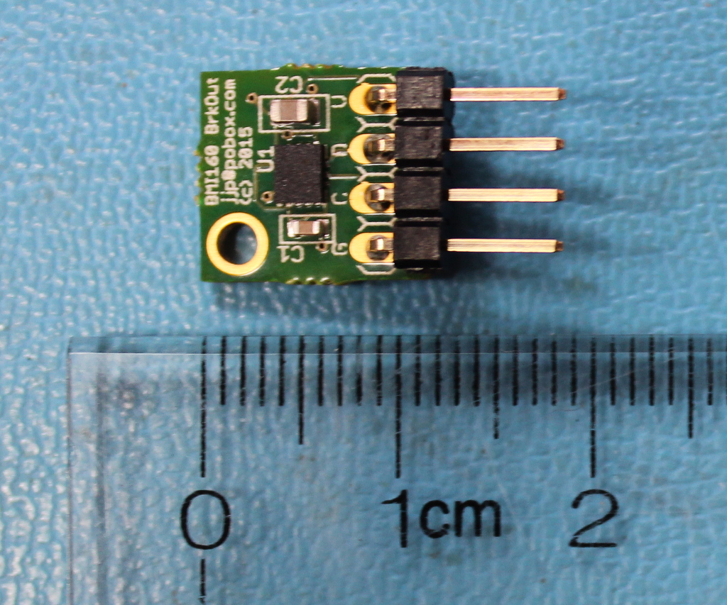
Completed BMI160 breakout board, Assembled by MacroFab
The first board is simple; it is a basically just a breakout board for the BMI160 inertial sensor. It provides the BMI160 itself, some decoupling capacitors, and a 0.1 inch 4 pin connector for the I2C bus.
I had these prototypes made at MacroFab which I highly recommend as a great provider of low-cost turnkey PCB assembly.
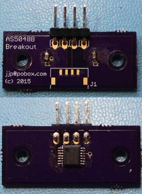
AS5048B breakout board
This, like the BMI160 breakout board, just has decoupling capacitors, the chip itself, and connectors. It additionally has mounting holes designed to fit onto the 3508 gimbal motor. This was printed at OSH Park and hand-assembled.
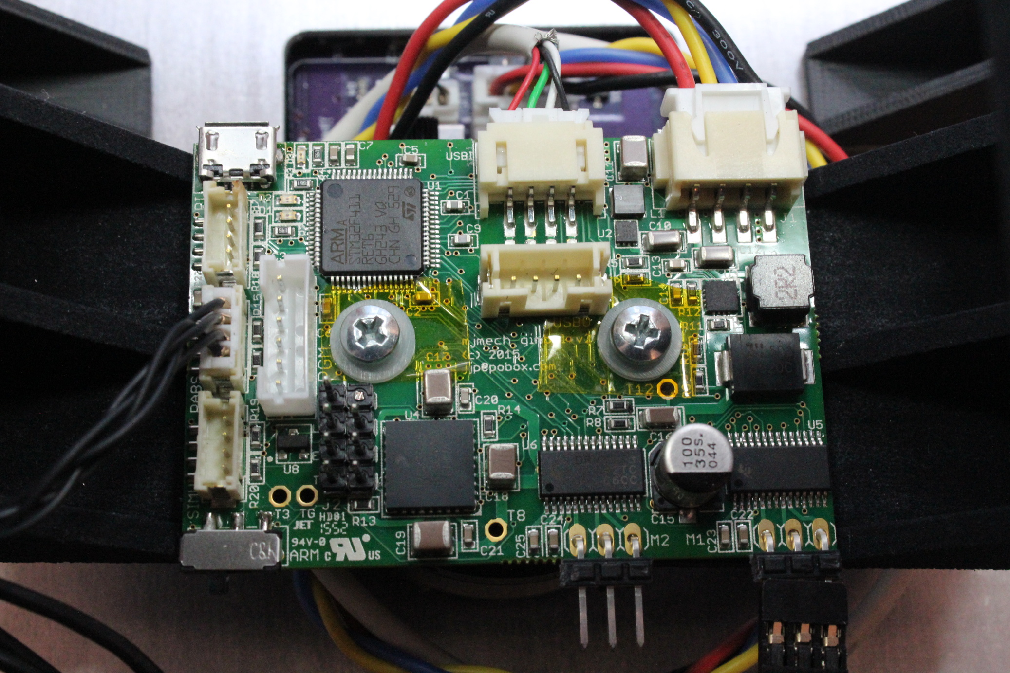
Completed primary gimbal control board (r2) , Assembled by MacroFab
The primary gimbal control board contains most of the system functionality. It is designed to mechanically mount directly above the yaw gimbal motor, as the yaw absolute magnetic encoder is in the center on the underside of the board.
This prototype was also built at MacroFab, who did an excellent job with this much more complex assembly.
The connectors and features are as follows:
struct Config {
  uint8_t address = 0xd0;
  uint16_t rate_hz = 800;
  uint16_t gyro_max_dps = 1000;
  uint8_t accel_max_g = 4;

  Euler offset_deg;

  template
  void Serialize(Archive* a) {
    a->Visit(MJ_NVP(address));
    a->Visit(MJ_NVP(rate_hz));
    a->Visit(MJ_NVP(gyro_max_dps));
    a->Visit(MJ_NVP(accel_max_g));
    a->Visit(MJ_NVP(offset_deg));
  }

  Config() {
    offset_deg.yaw = 90.0f;
  }
};
Sample configuration structure
The firmware was an experiment in writing modern C++11 code for the bare-metal STM32 platform. Each module interacts with others through std::function like callbacks, and the entire system is compiled both for the target, and the host so that unit tests are run. Dynamic memory allocation is this close to being disabled, but it was necessary for newlib’s floating point number formatting routines, which just allocate a chunk of memory the first time you use them. Otherwise, there is no dynamic memory used at all.
It relies on a CubeMX project template for this board. Most of the libraries CubeMX provides have too little flexilibity to be used for this application, so much of the bit twiddling is re-implemented in the gimbal firmware. CubeMX is great for configuring the clock tree and pin alternate functions however, especially in a complex project like this.
Both configuration and telemetry rely on a templated C++ visitor pattern to perform compile time reflection over mostly arbitrary C++ structures. Any module can register a structure to be used for persistent configuration. Those structures can be changed through the debugging protocol, and can be written to and read from flash at runtime. Each module can also register as many telemetry structures as necessary. These can be emitted over the debugging protocol either at fixed intervals, or whenever they update.
The IMU is converted into attitude through use of a simple complementary filter, in the same spirit as some of Seb Madgwick’s algorithms. This is then fed into a control loop for each axis’s gimbal.
There are three possible modes, the first of which is what I call “open-loop”, and is based on the same principles as the BruGi brushless gimbal, where no absolute motor feedback is available. In that mode, a PID controller operates with the axis error as the input, and the output is the actual phase position of the BLDC controller. In this mode, the integral term does most of the work in stabilization, so the overall performance isn’t great.
The second mode still uses a PID controller, but now the output is an offset to the BLDC phase necessary to hold the current position as measured by the absolute encoders. This effectively makes the output a direct mapping to force applied to the motor, although of course a non-linear mapping. This mode results in much better overall performance and is easier to tune.
Finally, there is a third debugging mode that lets you just hard command specific BLDC phases. This is useful for calibrating the mapping between BLDC phase and absolute encoder phase.
The debugging protocol is partially human readable, but telemetry data is encoded in the same binary format as used elsewhere in the mjmech codebase. tview is the debugging application we use to read that data, as well as configure and control the overall system.
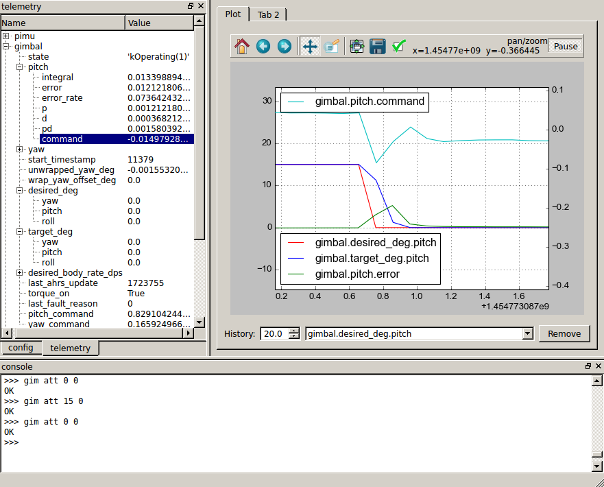
tview window
The bottom pane just has a serial console, where you can send arbitrary things over the virtual serial port. tview directly supports relatively few commands from the debugging protocol, and for instance has no UI to operate the stabilizer or fire control, so for now these are done by hand in that window.
The left pane has two tabs, one with a configuration tree and the other with a telemetry tree. The configuration tree shows all structures which were registered as configurable, and allows you to change them in the live system. The telemetry tree shows all structures registered as telemetry structures, and reports their values live as the system is operating.
The right pane has a live plot window where any of the values in the telemetry tree can be plotted versus time. It is just an embedded matplotlib plot, so all the normal plot interaction tools are available, plus some from mjmech’s tplot, like the ability to pan and zoom the left and right axes independently.
And last but not least, here is a short video demonstrating the turret stabilizing a camera and firing some blanks at a target as our mech walks around.
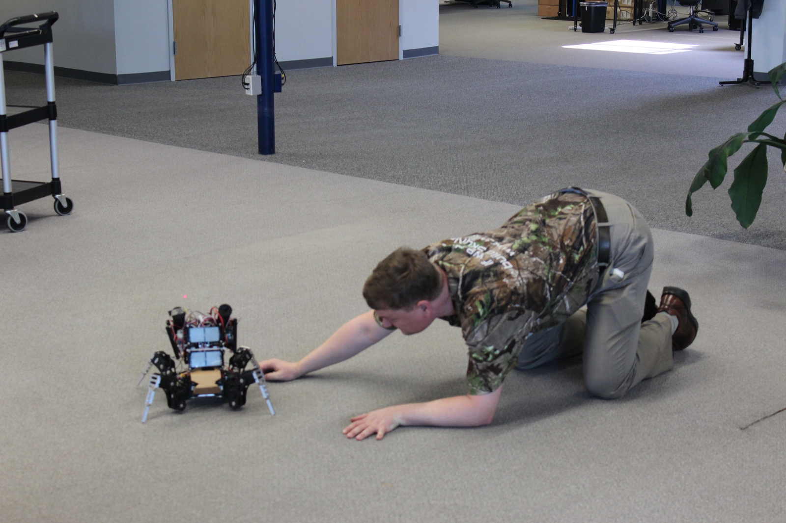
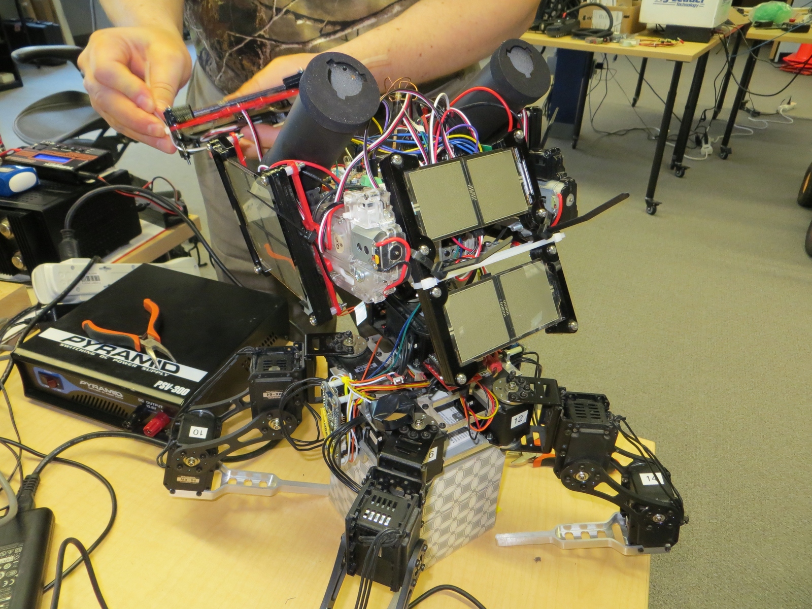
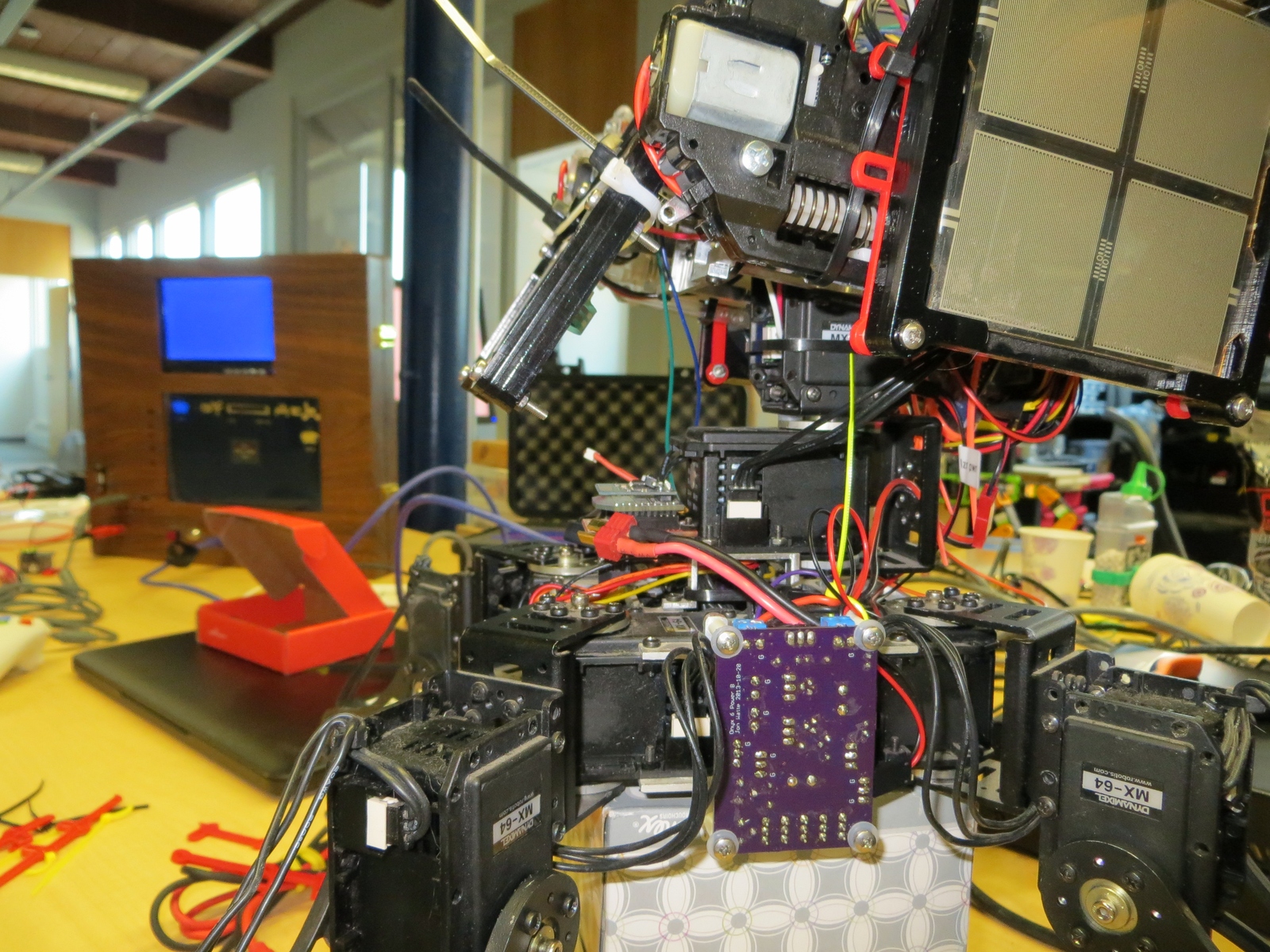
I have some incremental progress to report on various parts of Super Mega Microbot. First, I have a draft fully assembled leg for a mammal walking configuration. It is mostly just the stock Dongbu brackets, with a custom Shapeways print at the final joint holding a standoff and rubber stopper.
Prototype mammal jointed leg
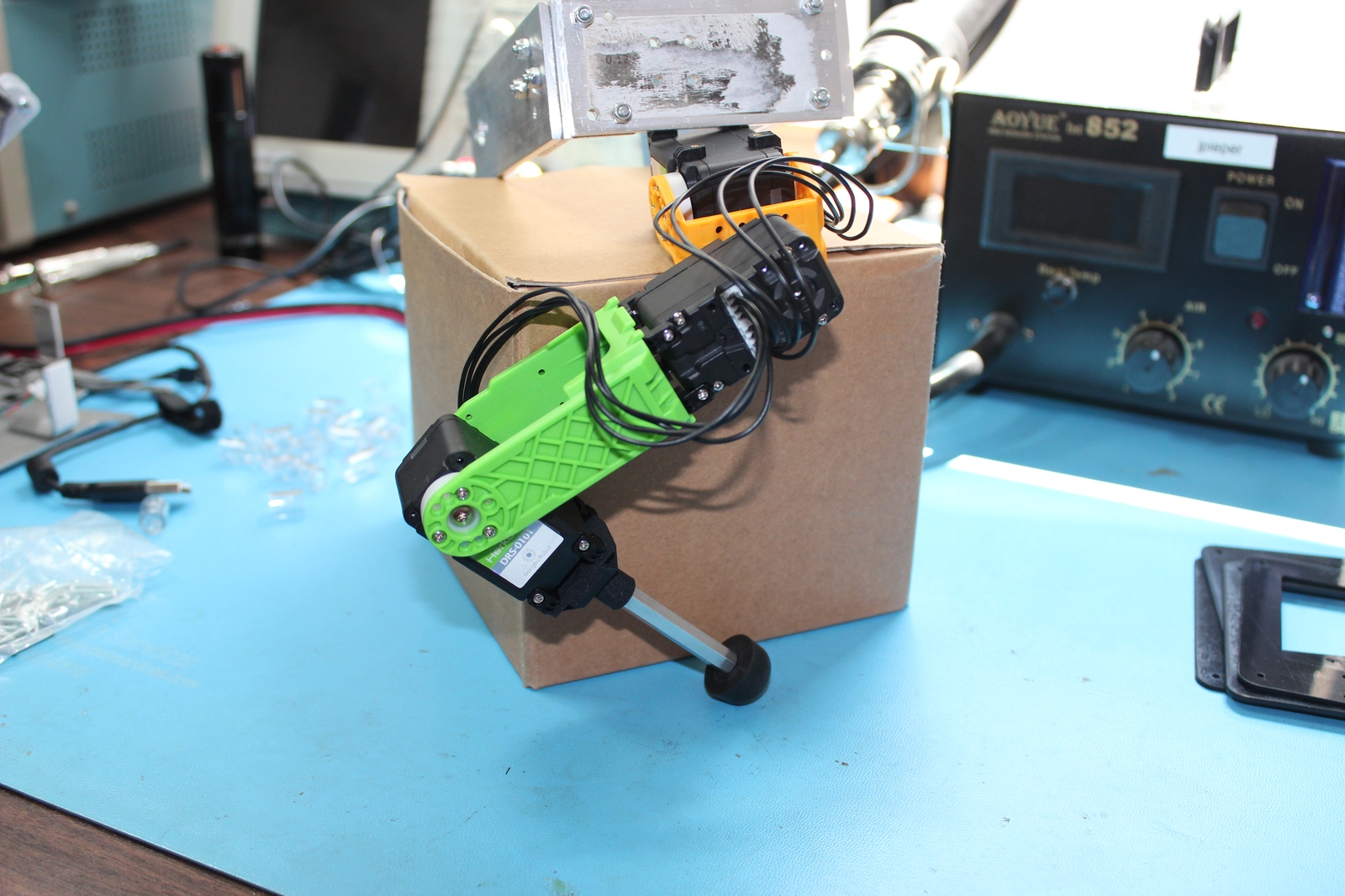
Second, I’ve been working on a gimbal stabilized turret. I have video from a prior incarnation below:
And a first draft of a 3D printed turret bracket that permits a full range of motion of the turret:
3D printed turret gimbal bracket
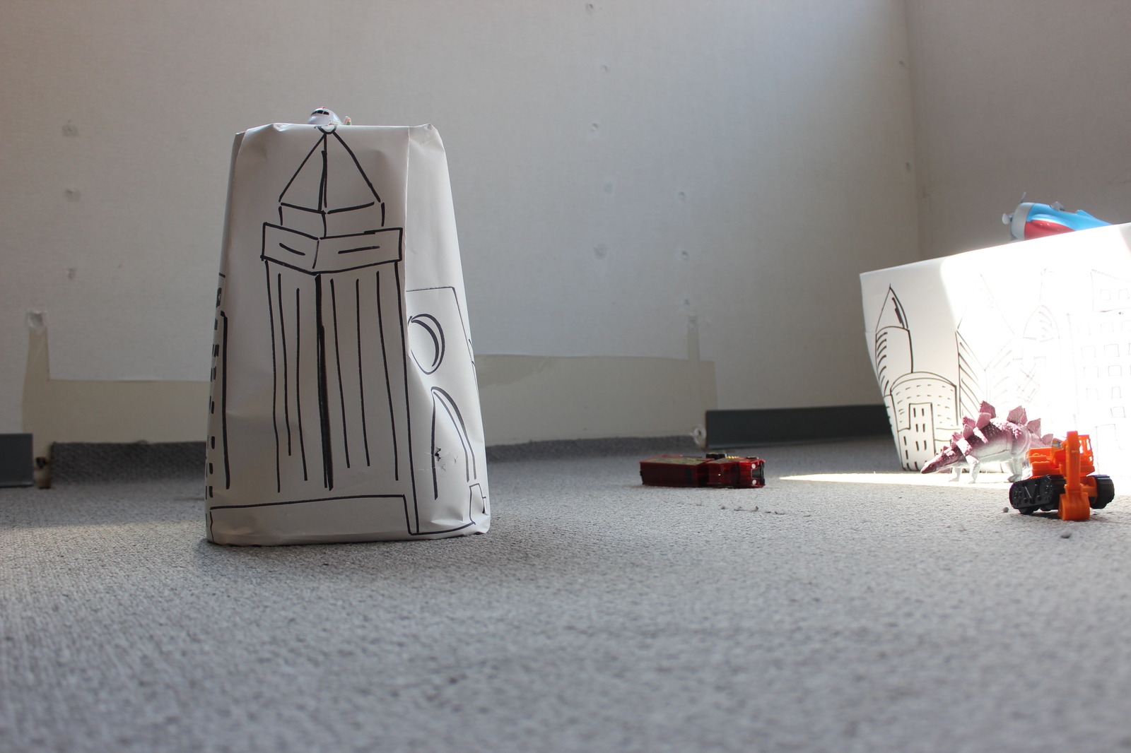
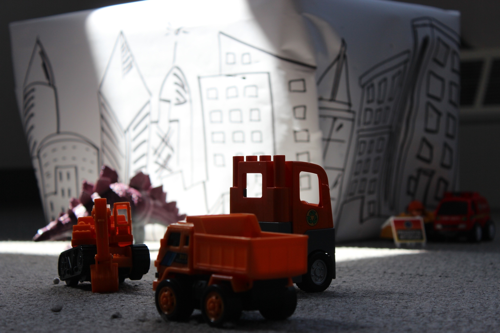
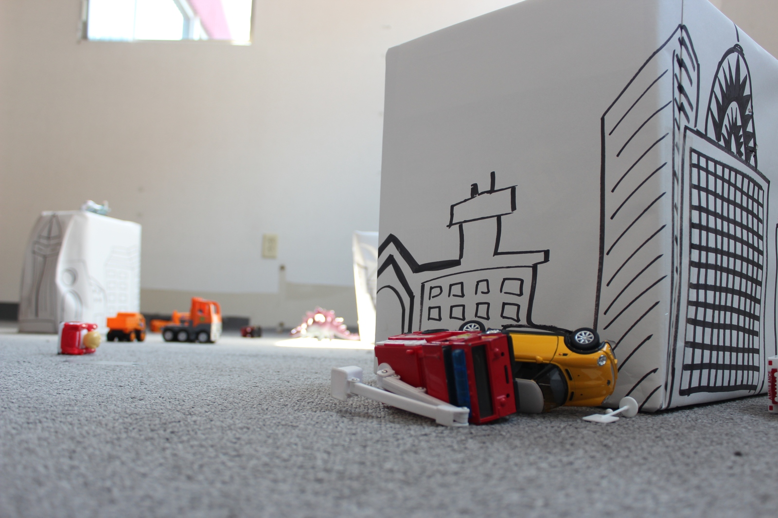
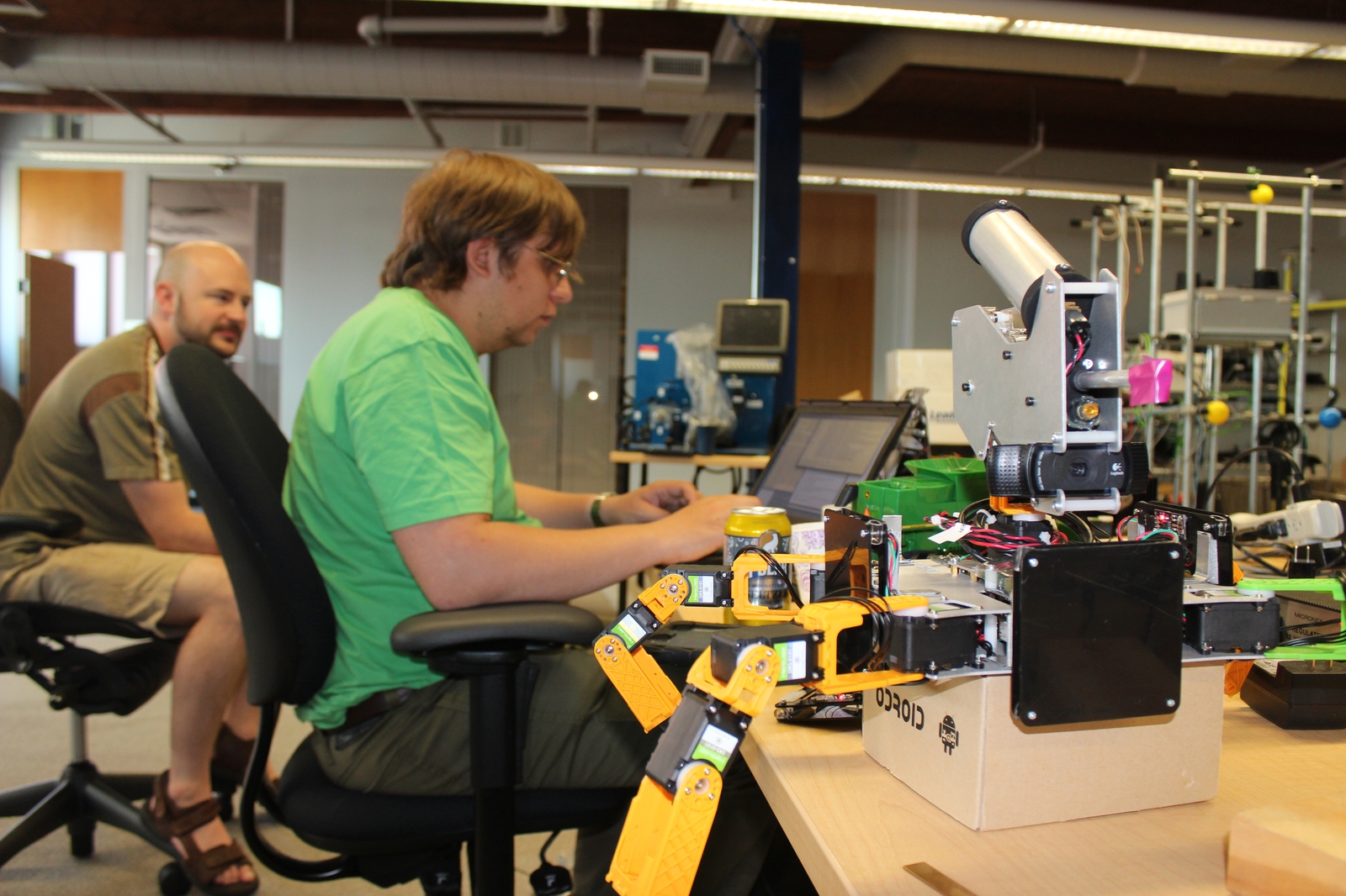
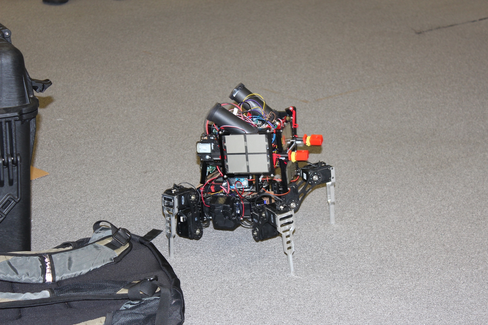
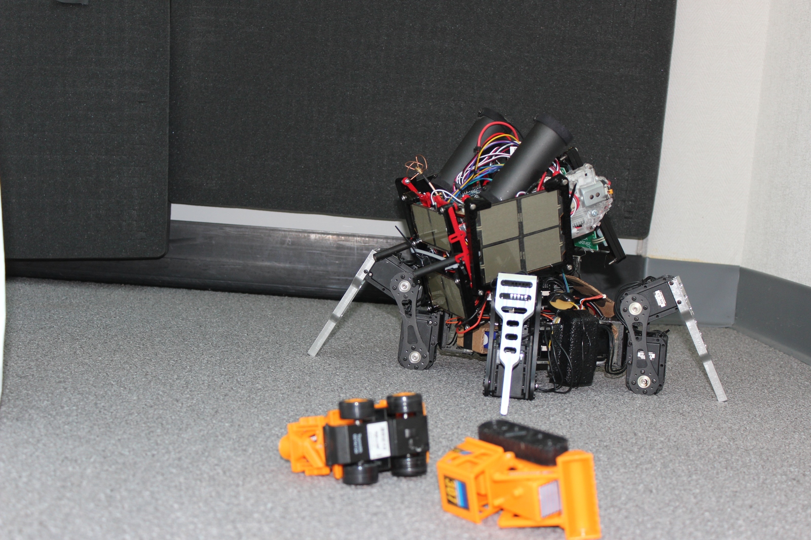
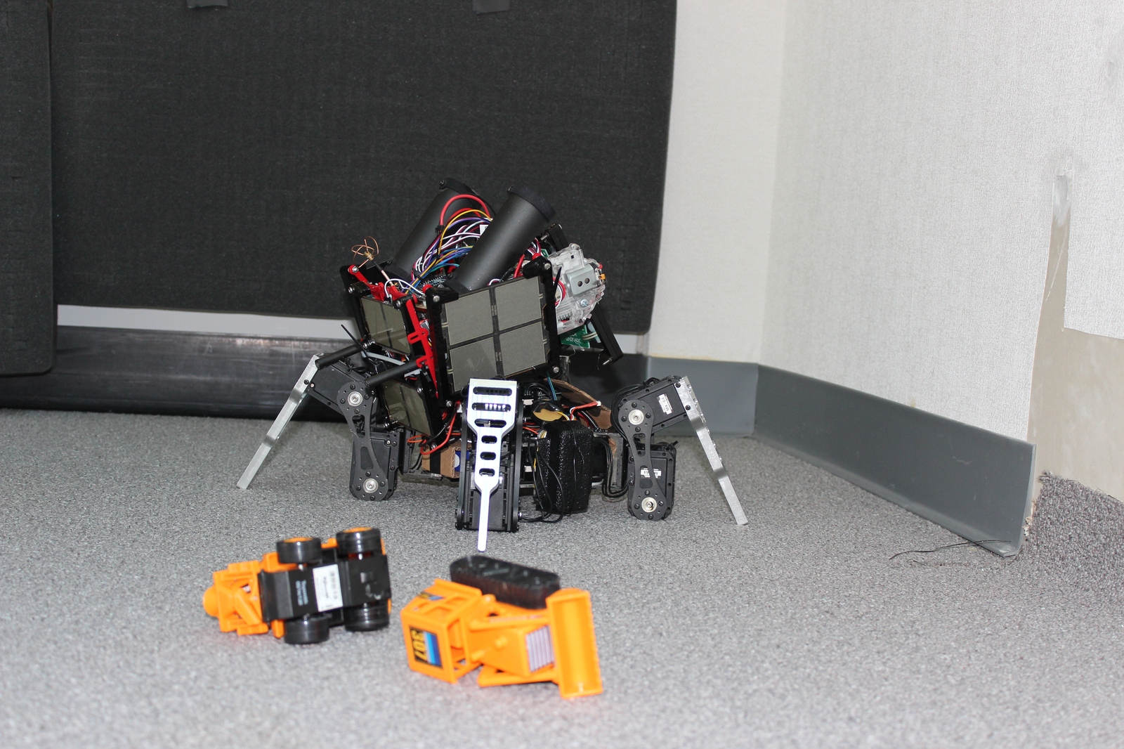
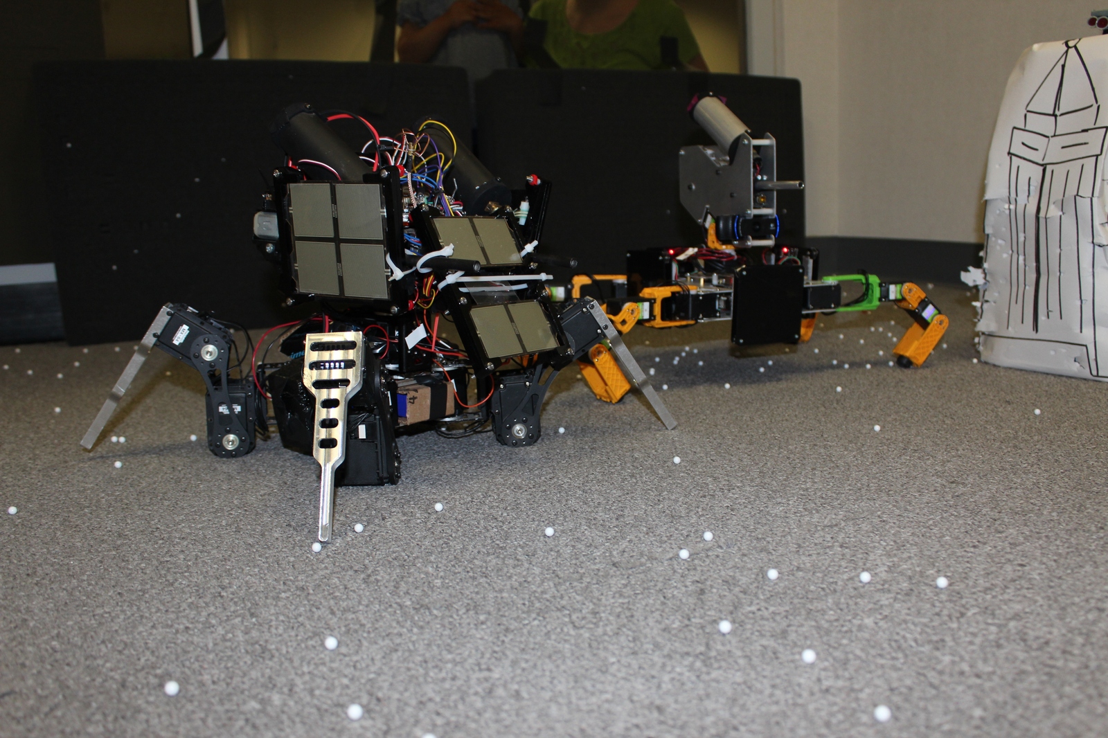
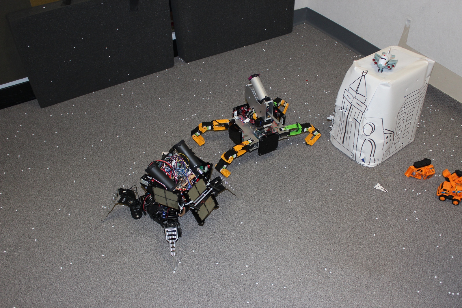
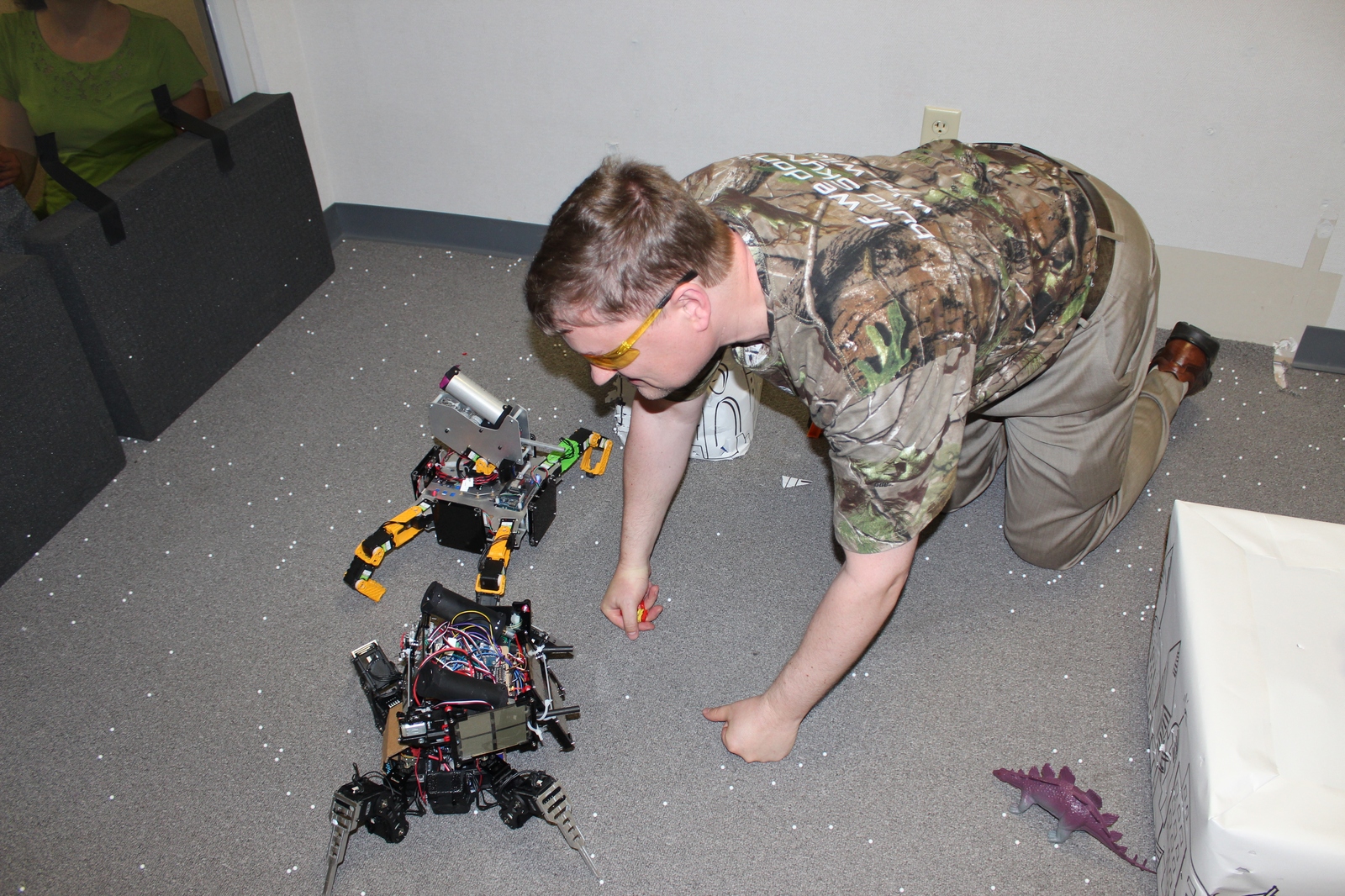
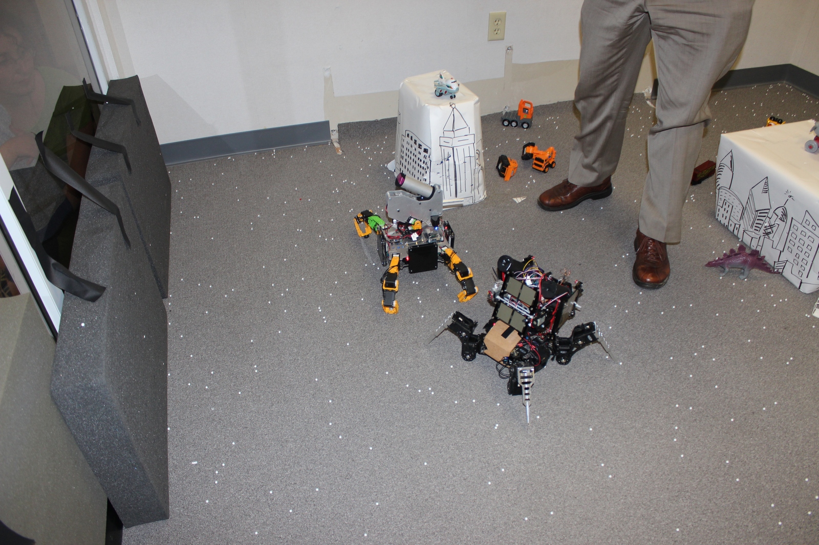
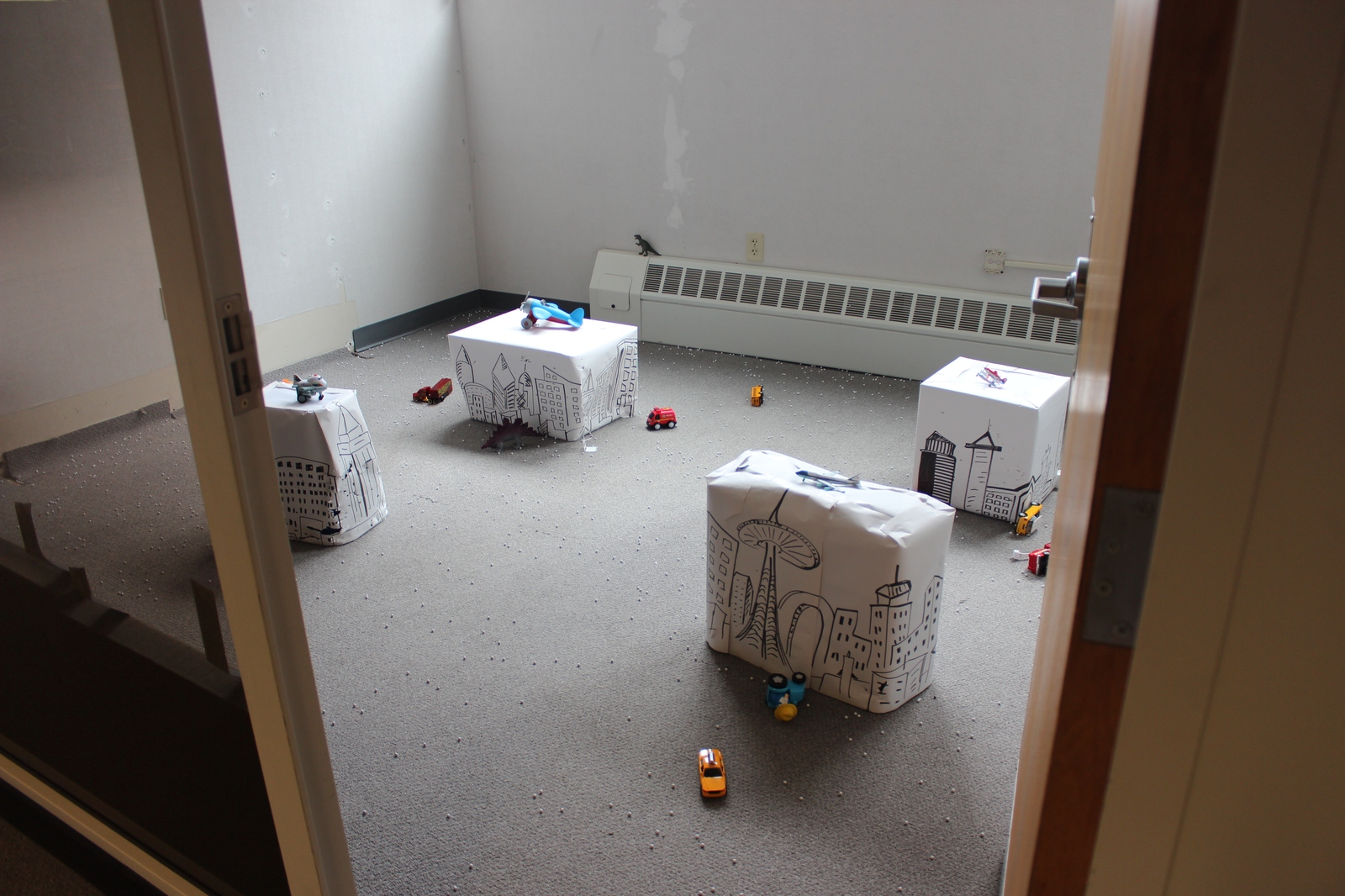
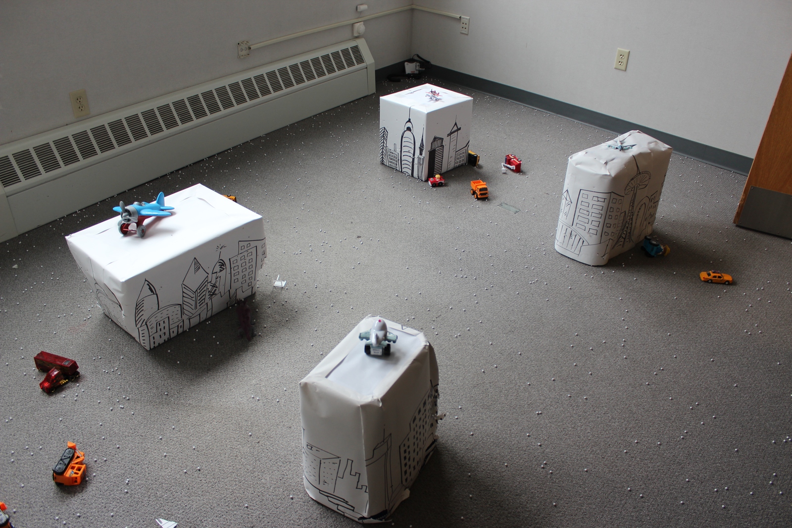
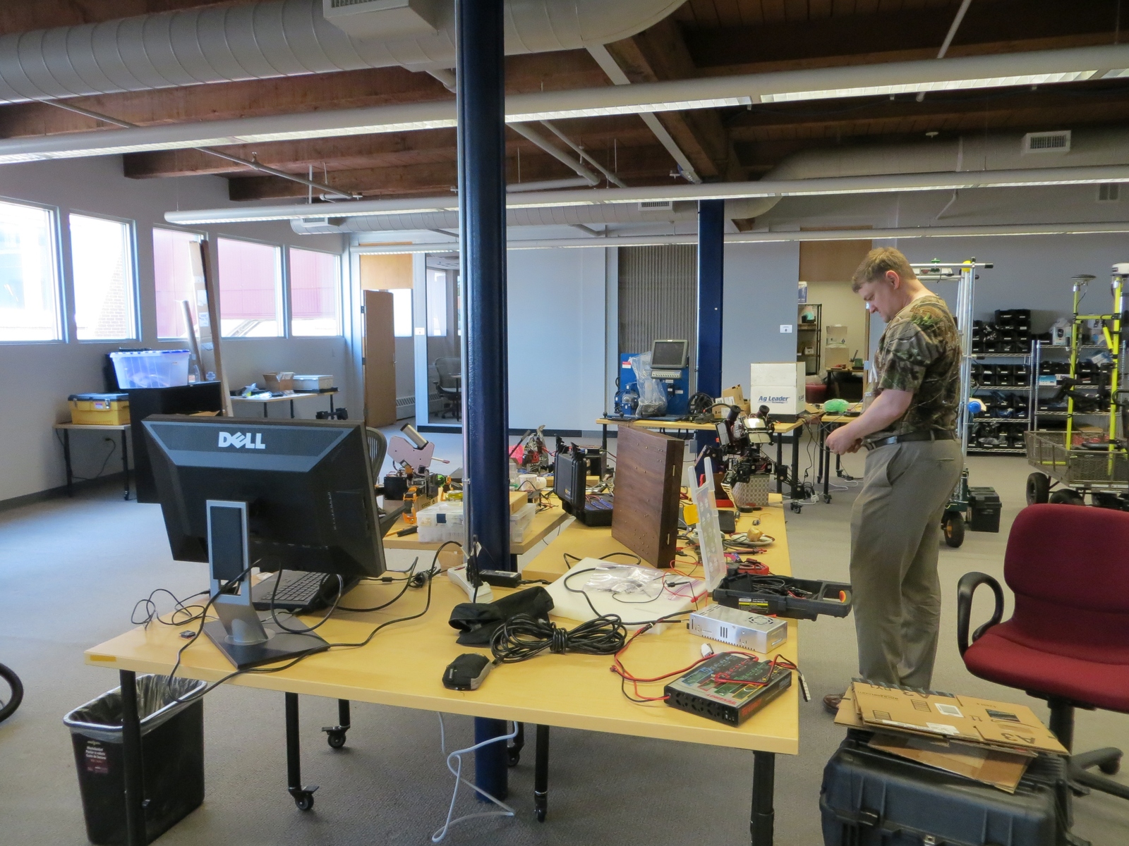
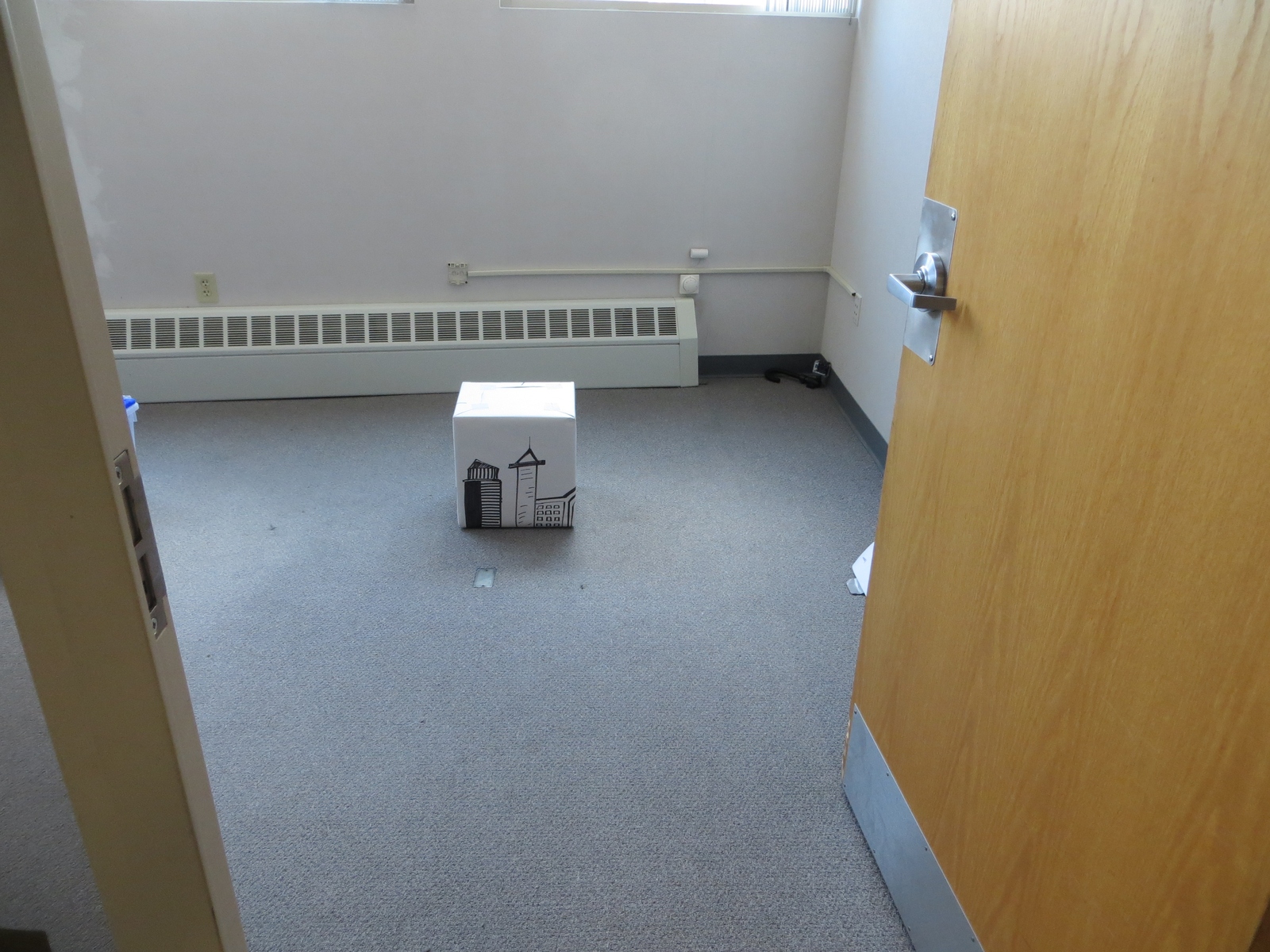
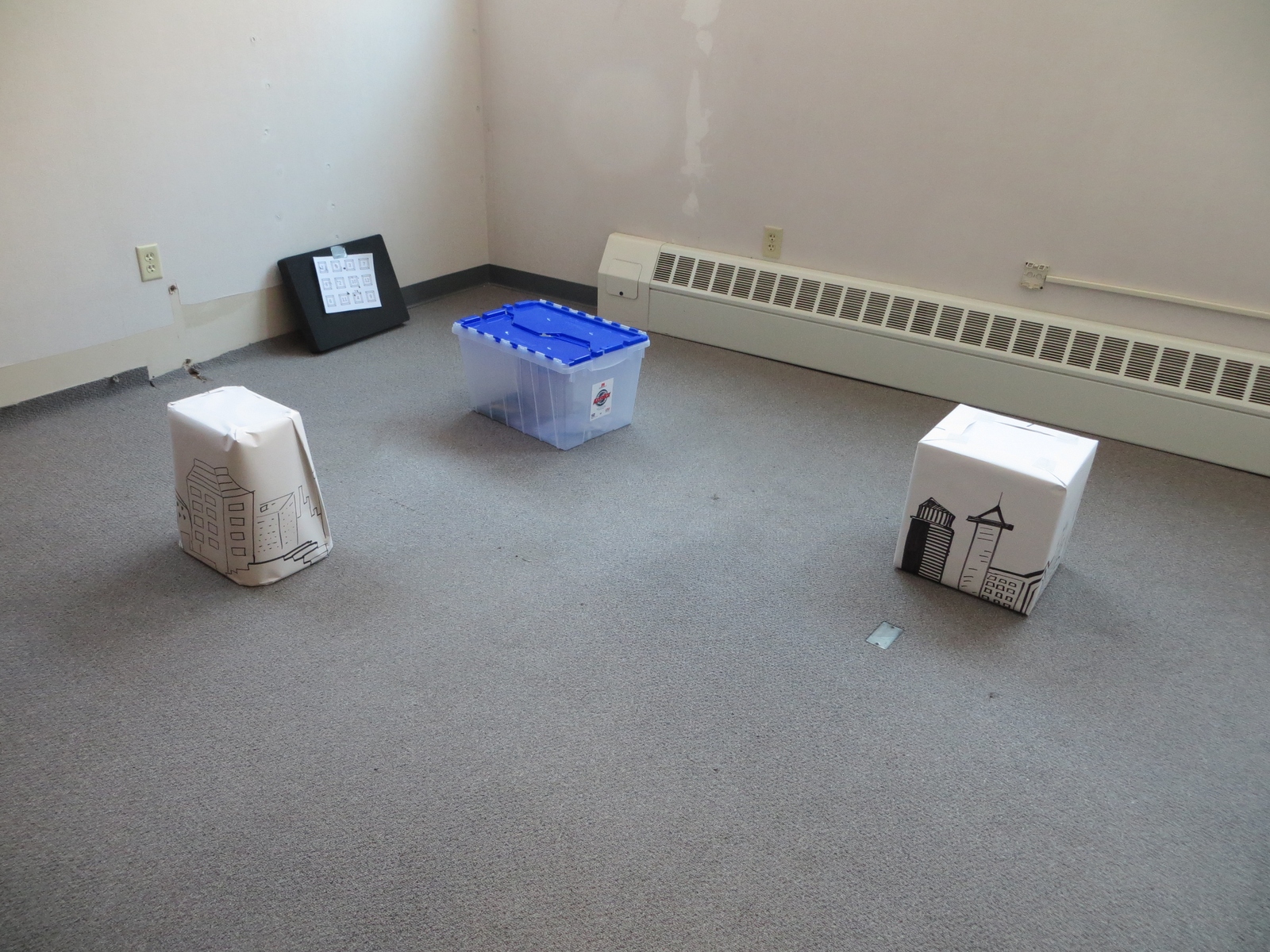
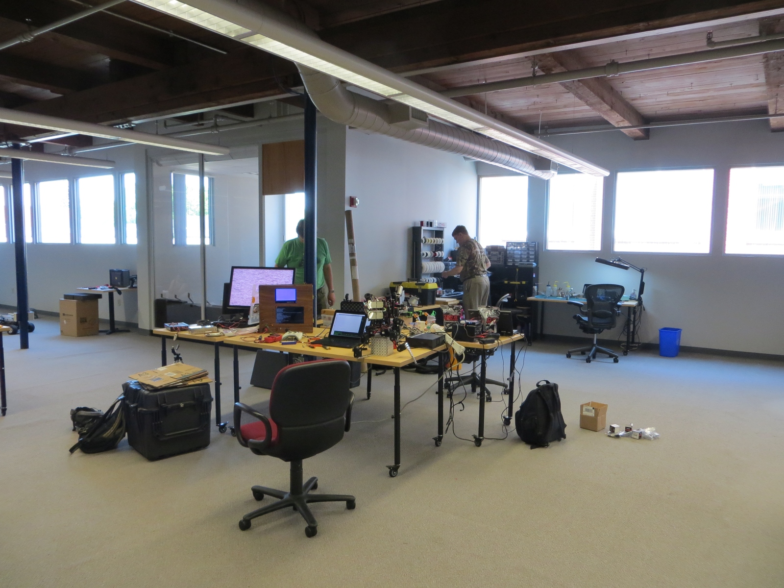
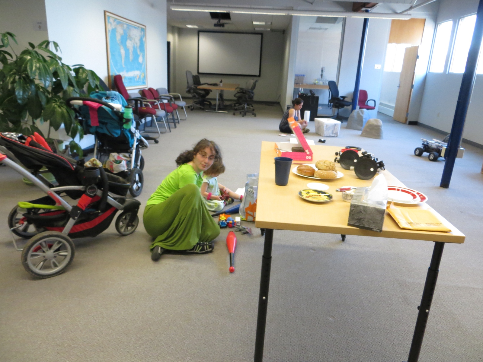
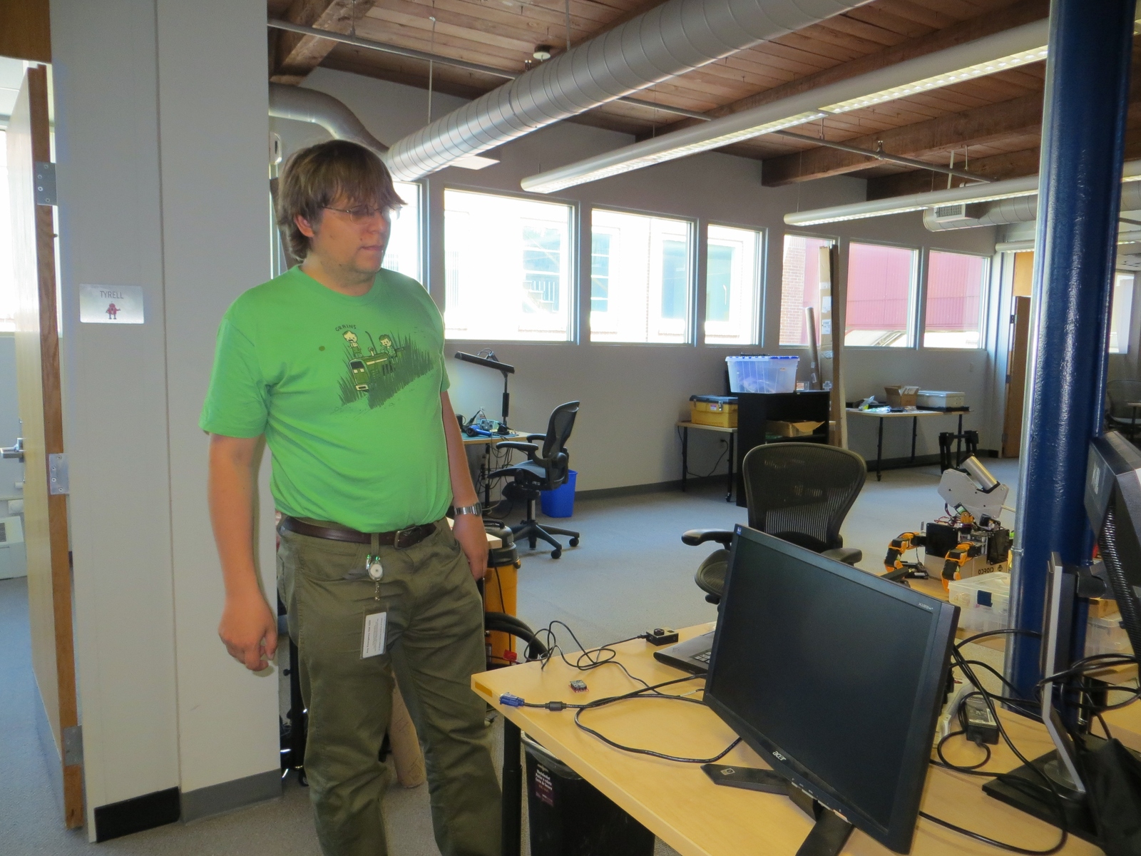
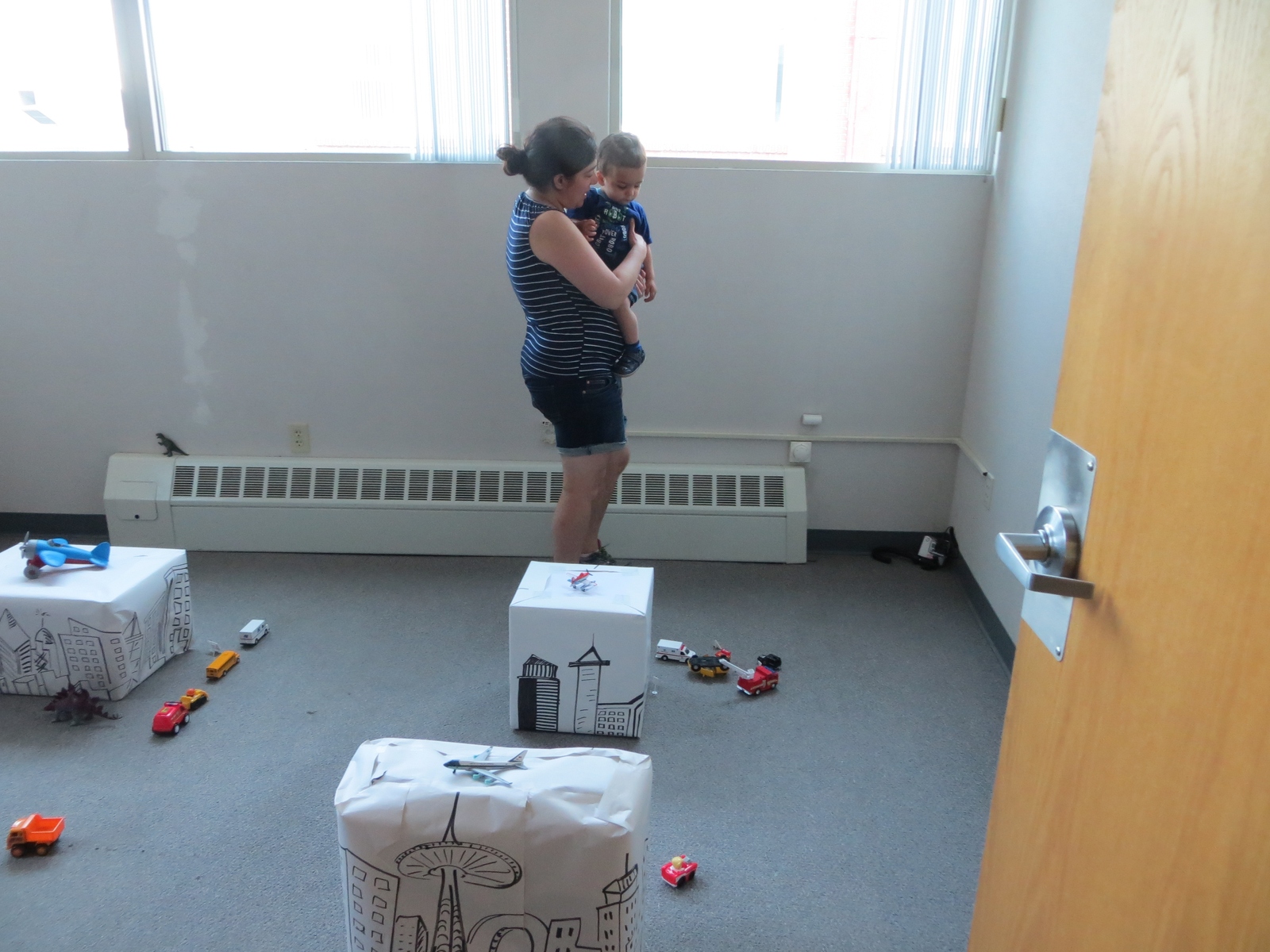
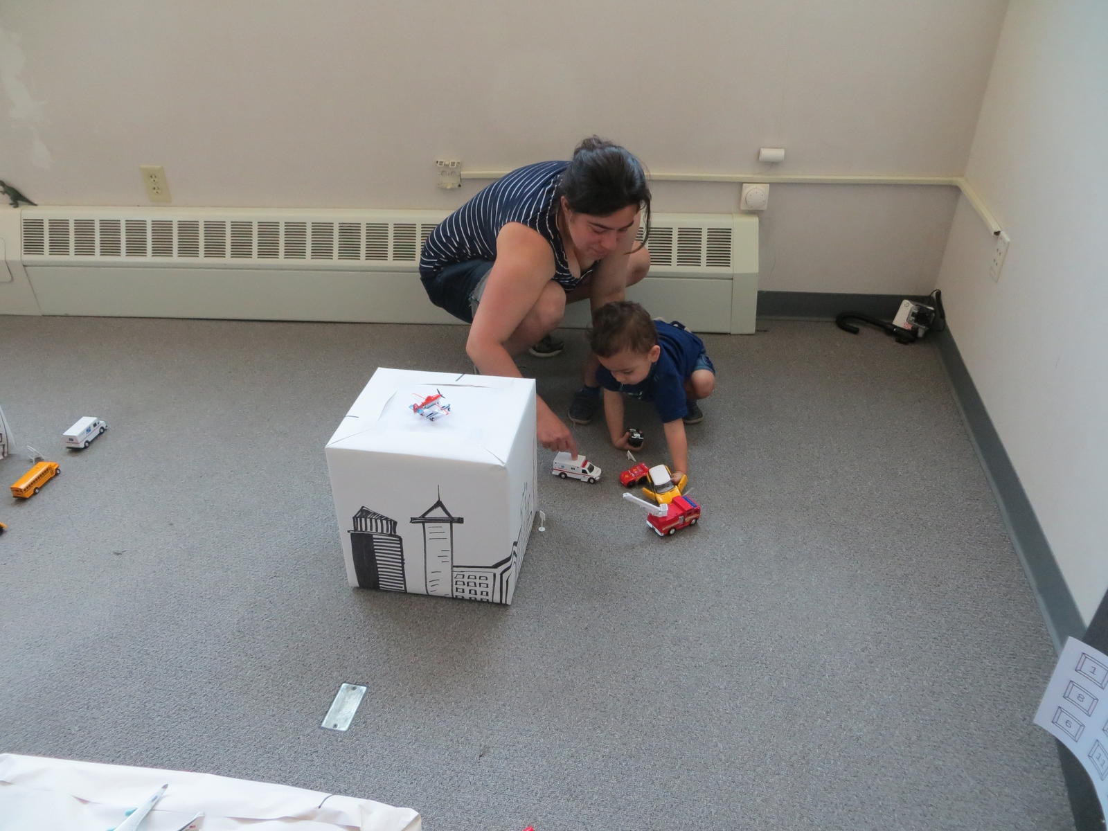
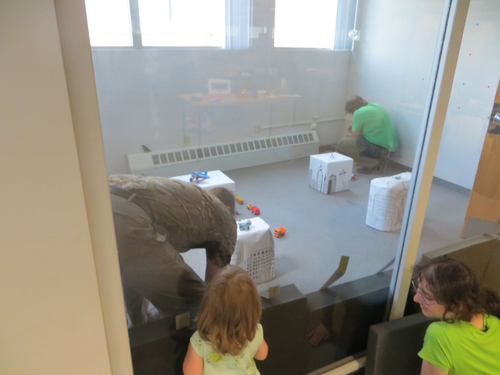
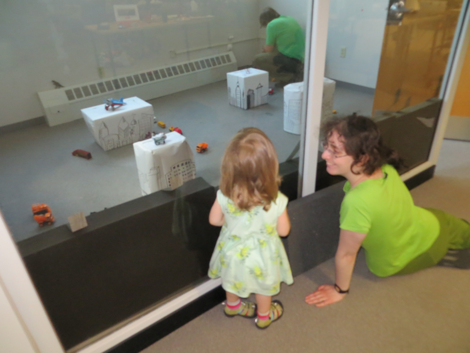
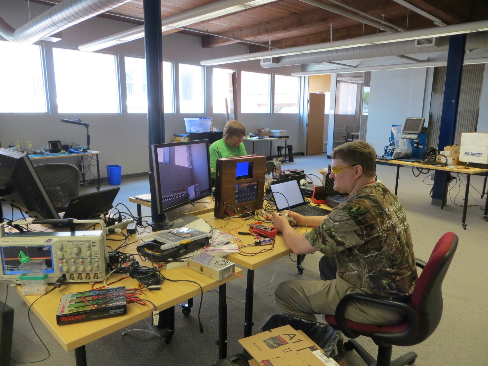
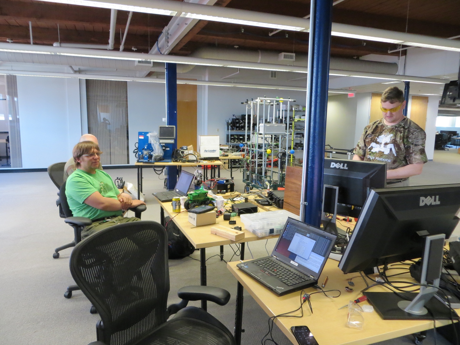
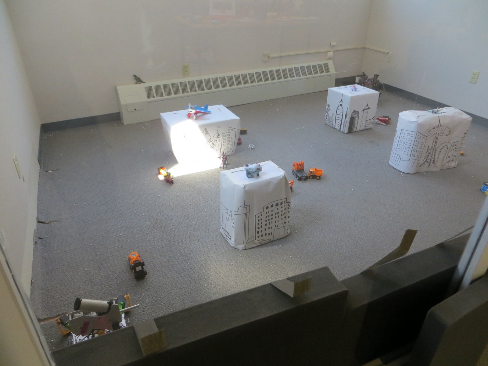
We just concluded the first ever Boston Mech Warfare Expo this weekend, held at Jaybridge Robotics in Cambridge. We had a lot of exciting mech fighting action, learned a lot, and even had a fair amount of exciting repairs! There are many hours of video I need to sort through, but in the meantime, here are some photos:
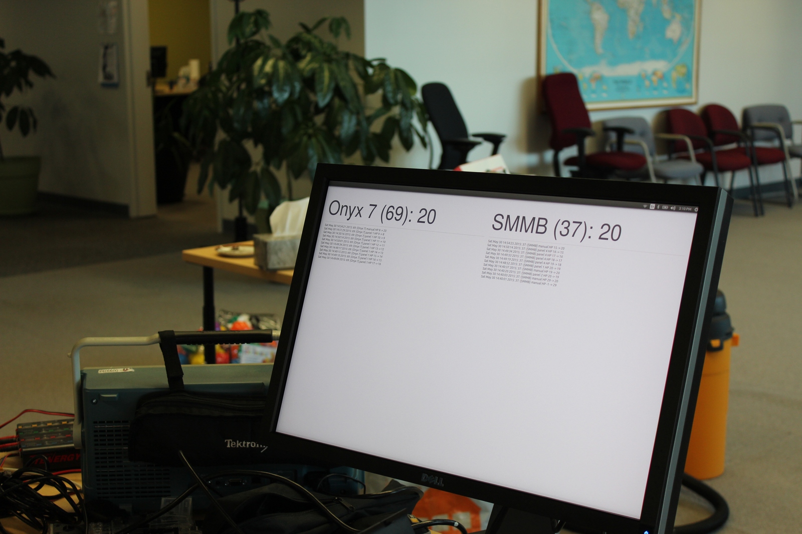

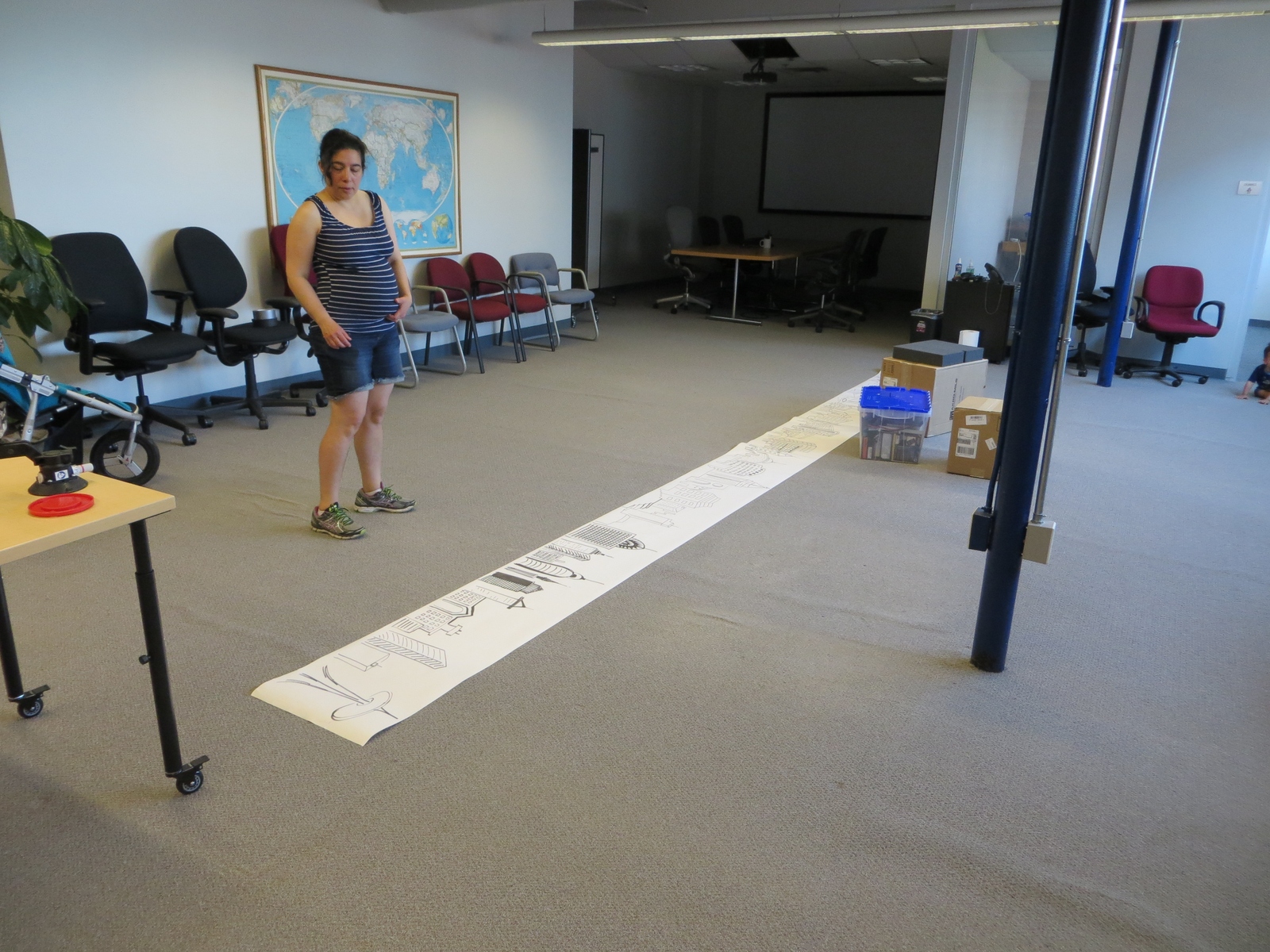
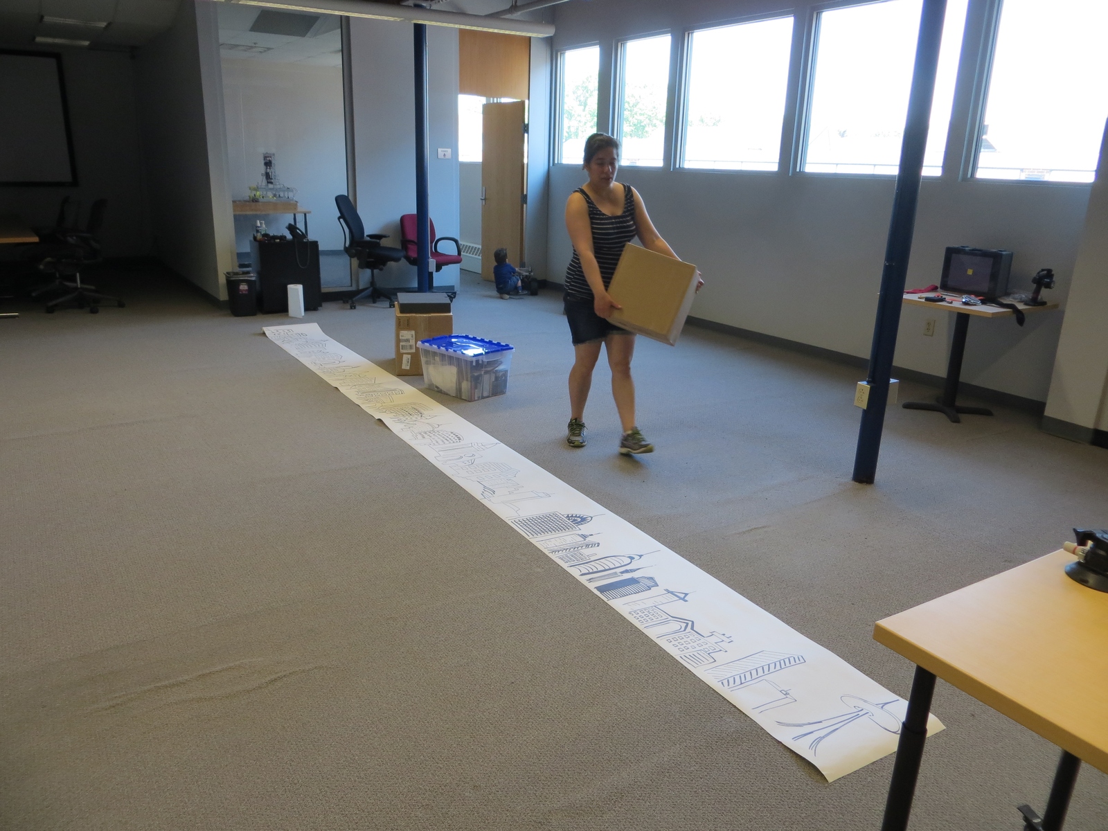
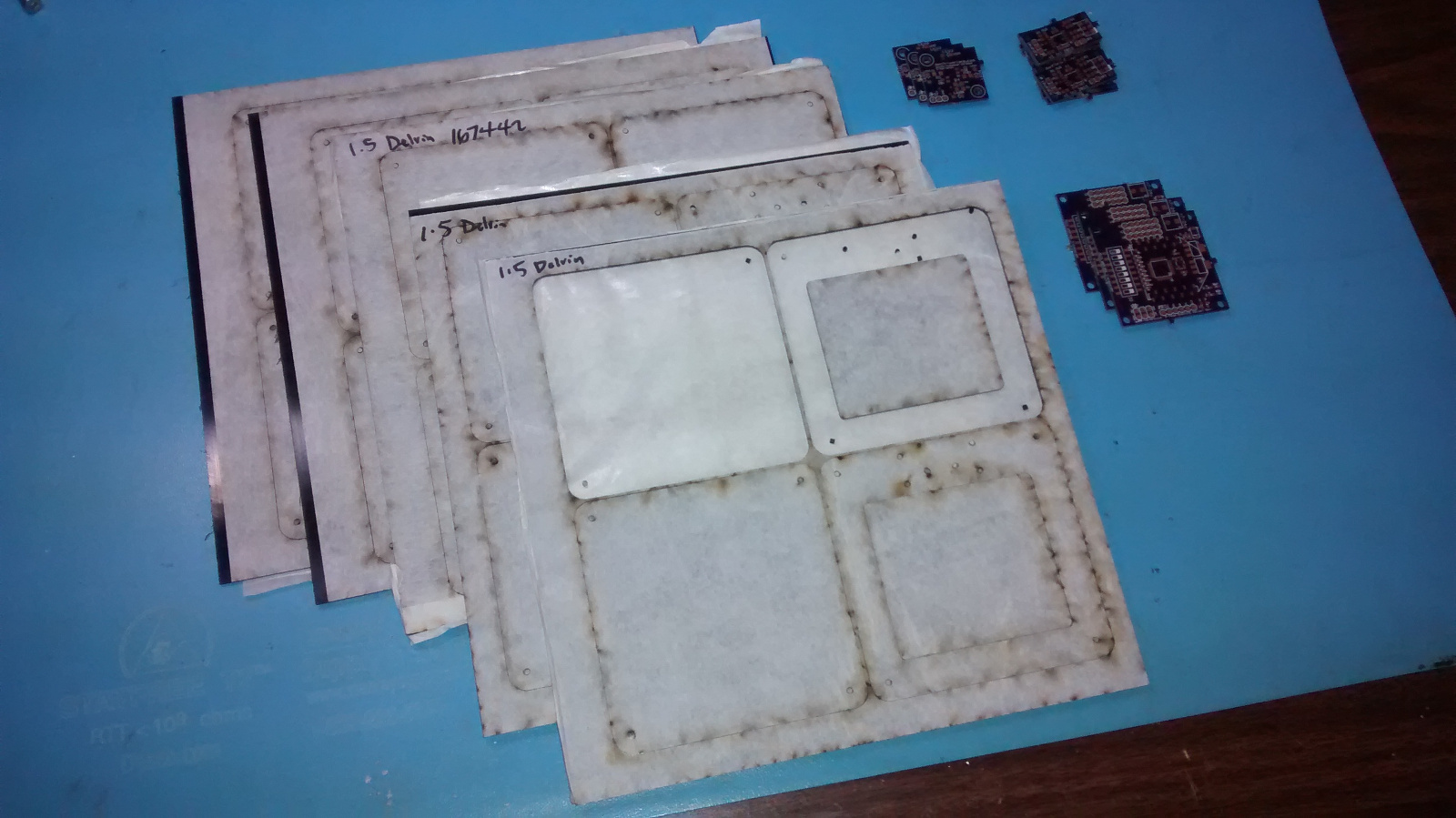
A whole lot of laser cut parts and printed boards just arrived for the scoring system for Super Mega Microbot. We’ll get them put together and tested soon!