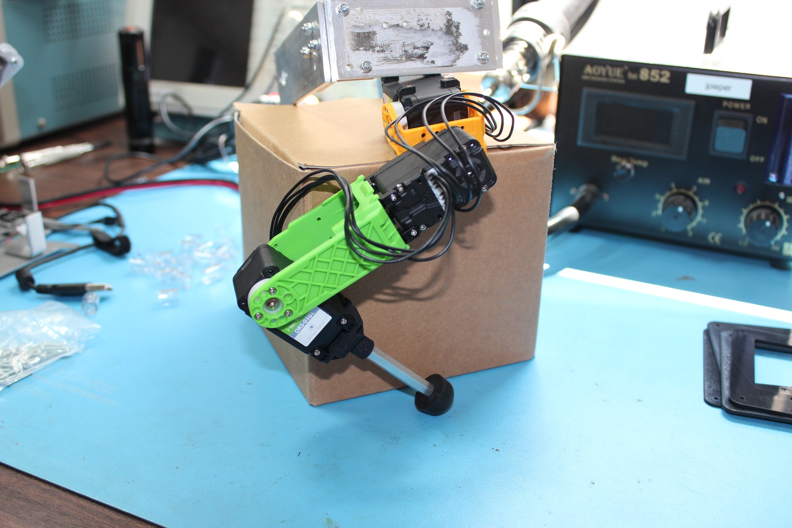
I have some incremental progress to report on various parts of Super Mega Microbot. First, I have a draft fully assembled leg for a mammal walking configuration. It is mostly just the stock Dongbu brackets, with a custom Shapeways print at the final joint holding a standoff and rubber stopper.
Prototype mammal jointed leg
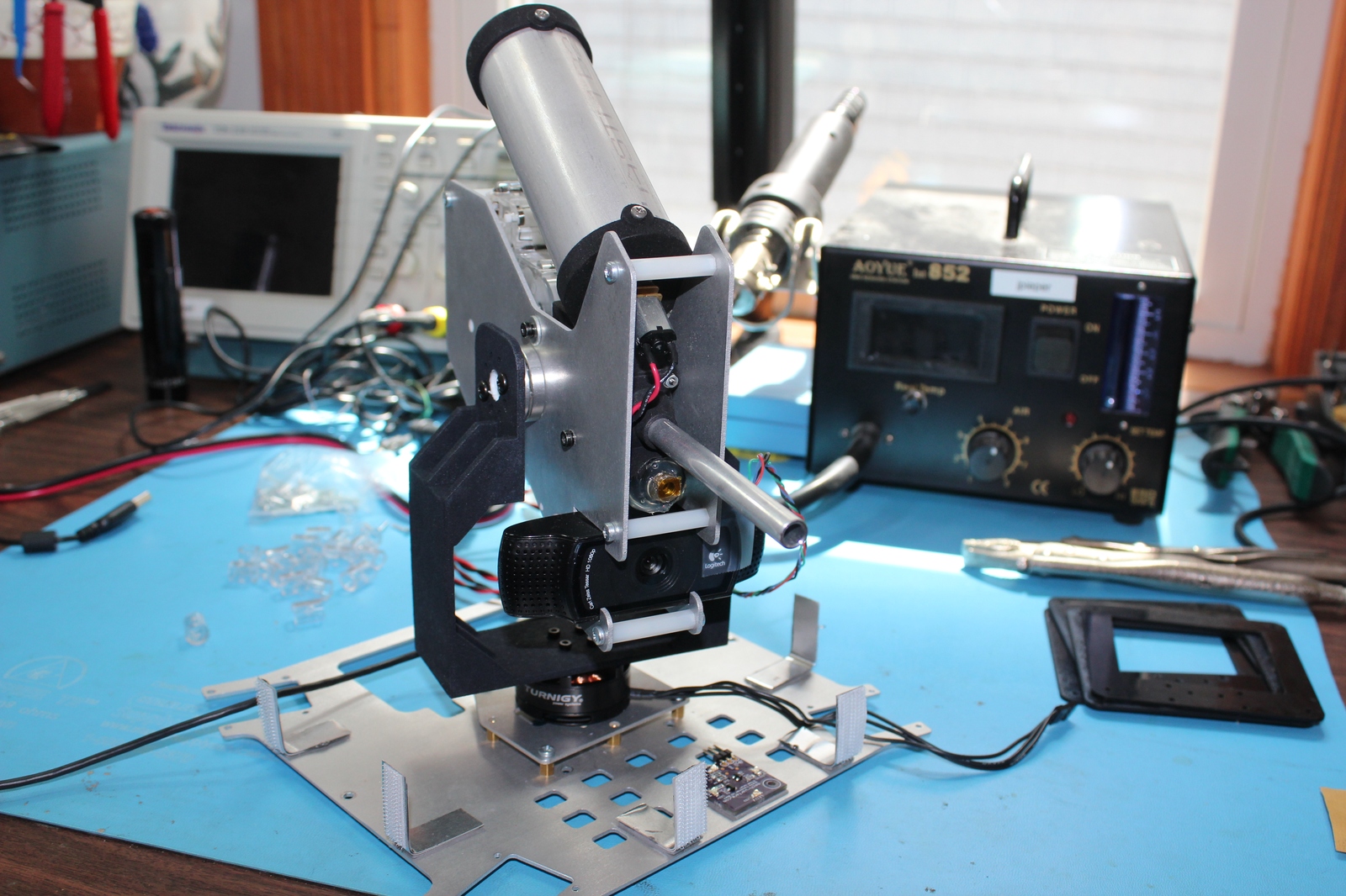
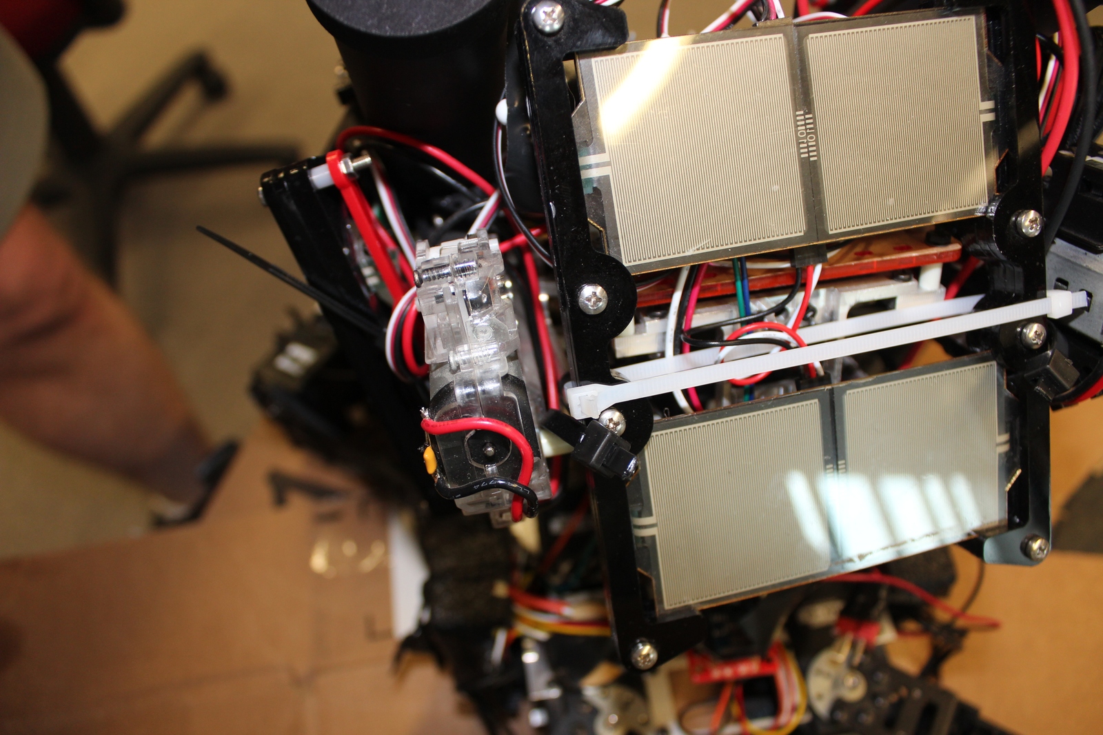
Second, I’ve been working on a gimbal stabilized turret. I have video from a prior incarnation below:
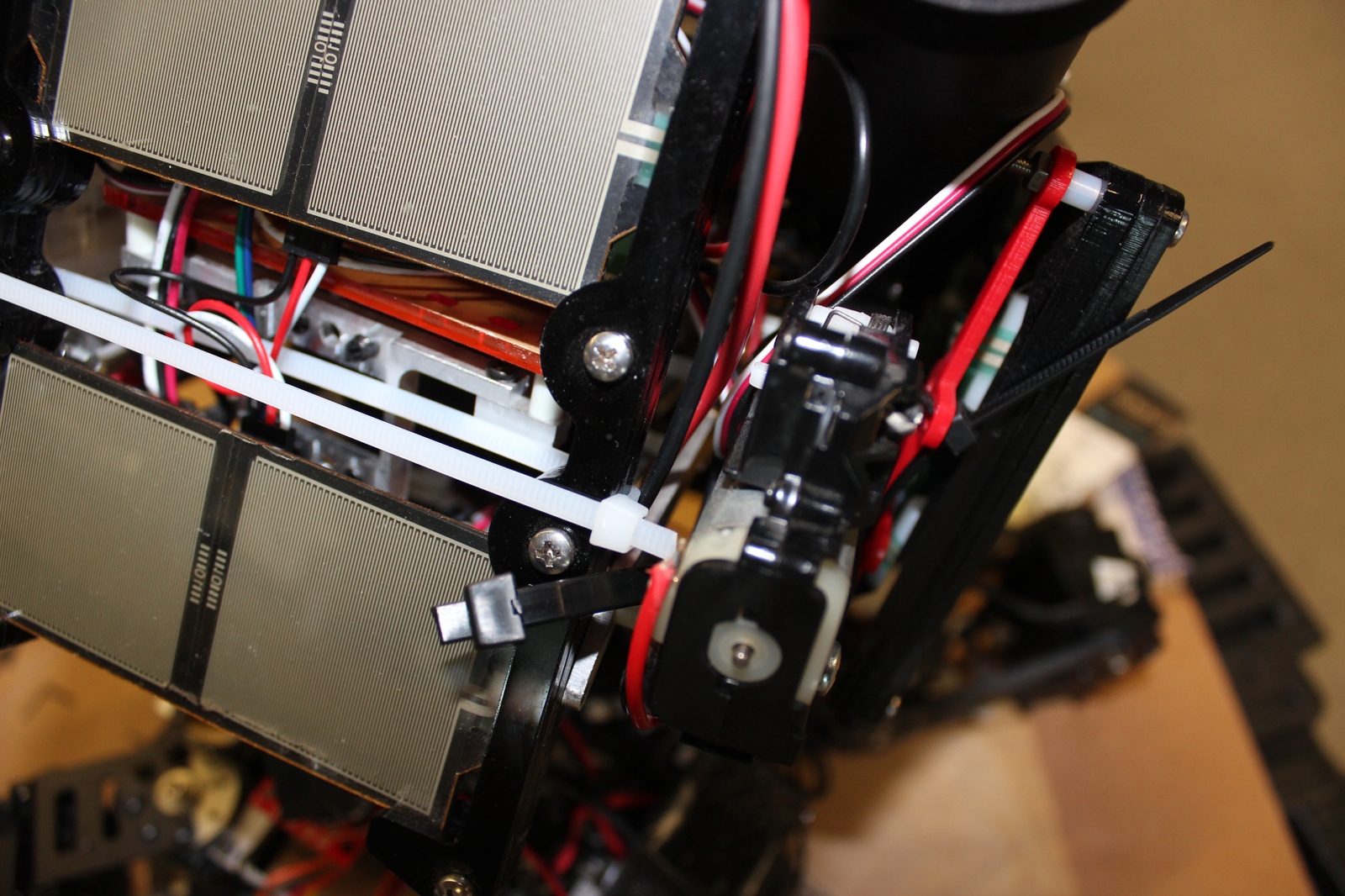
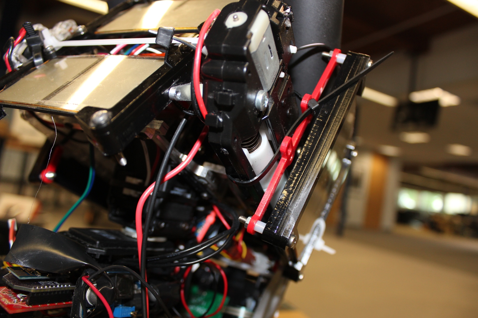
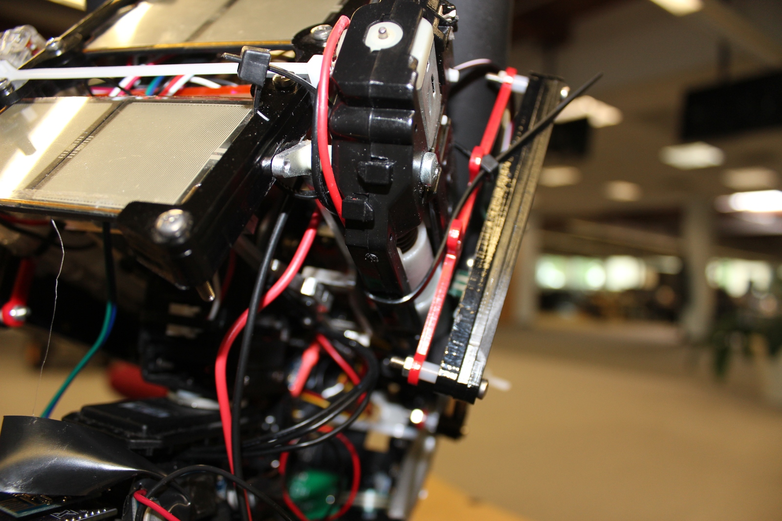
And a first draft of a 3D printed turret bracket that permits a full range of motion of the turret:
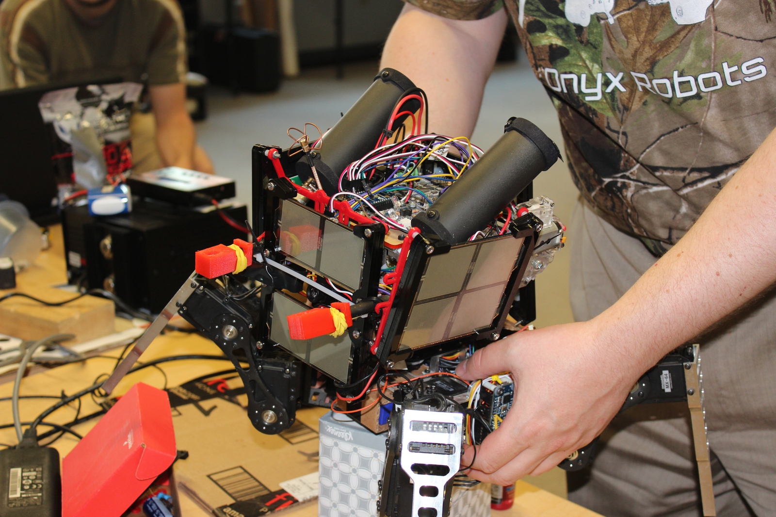
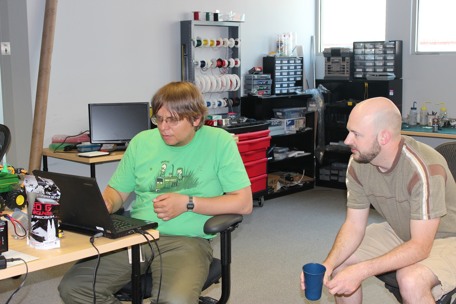
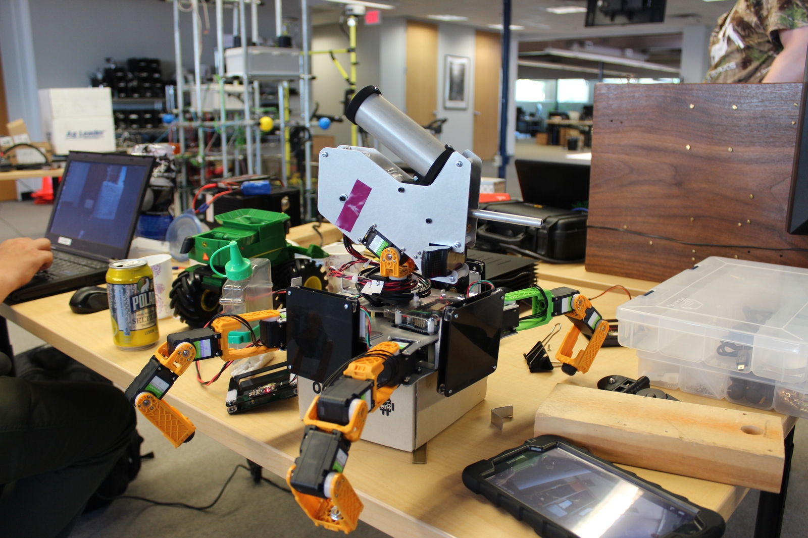
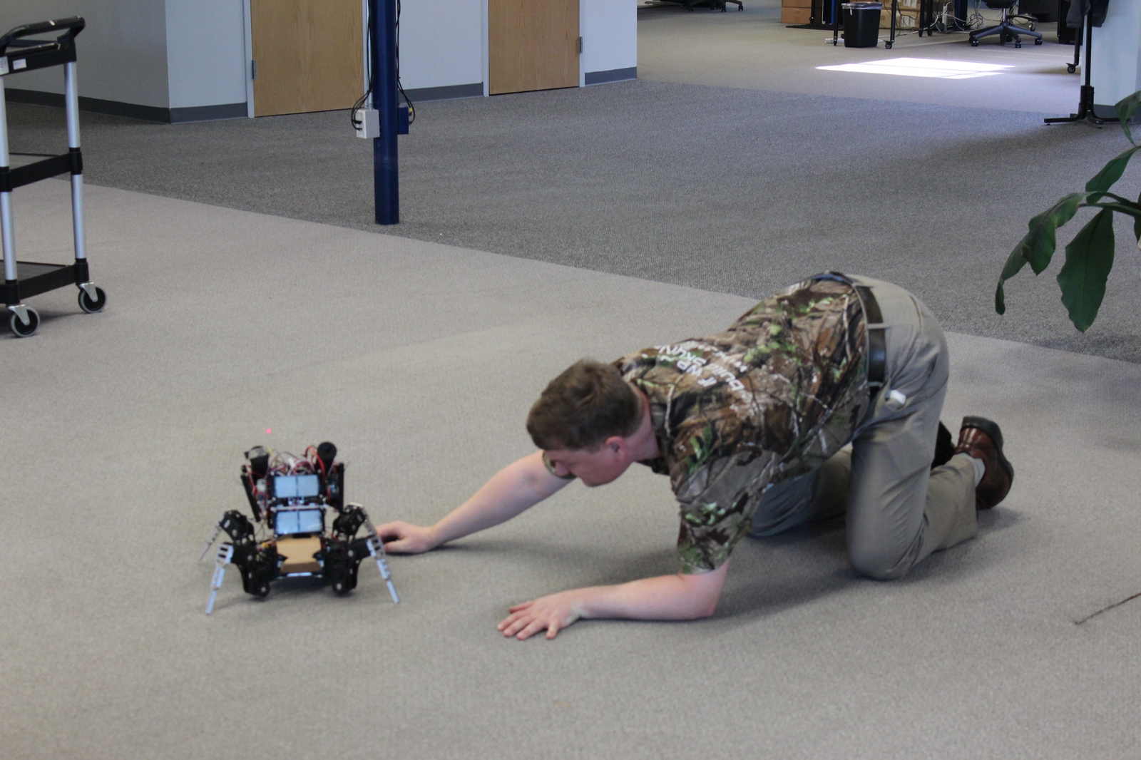
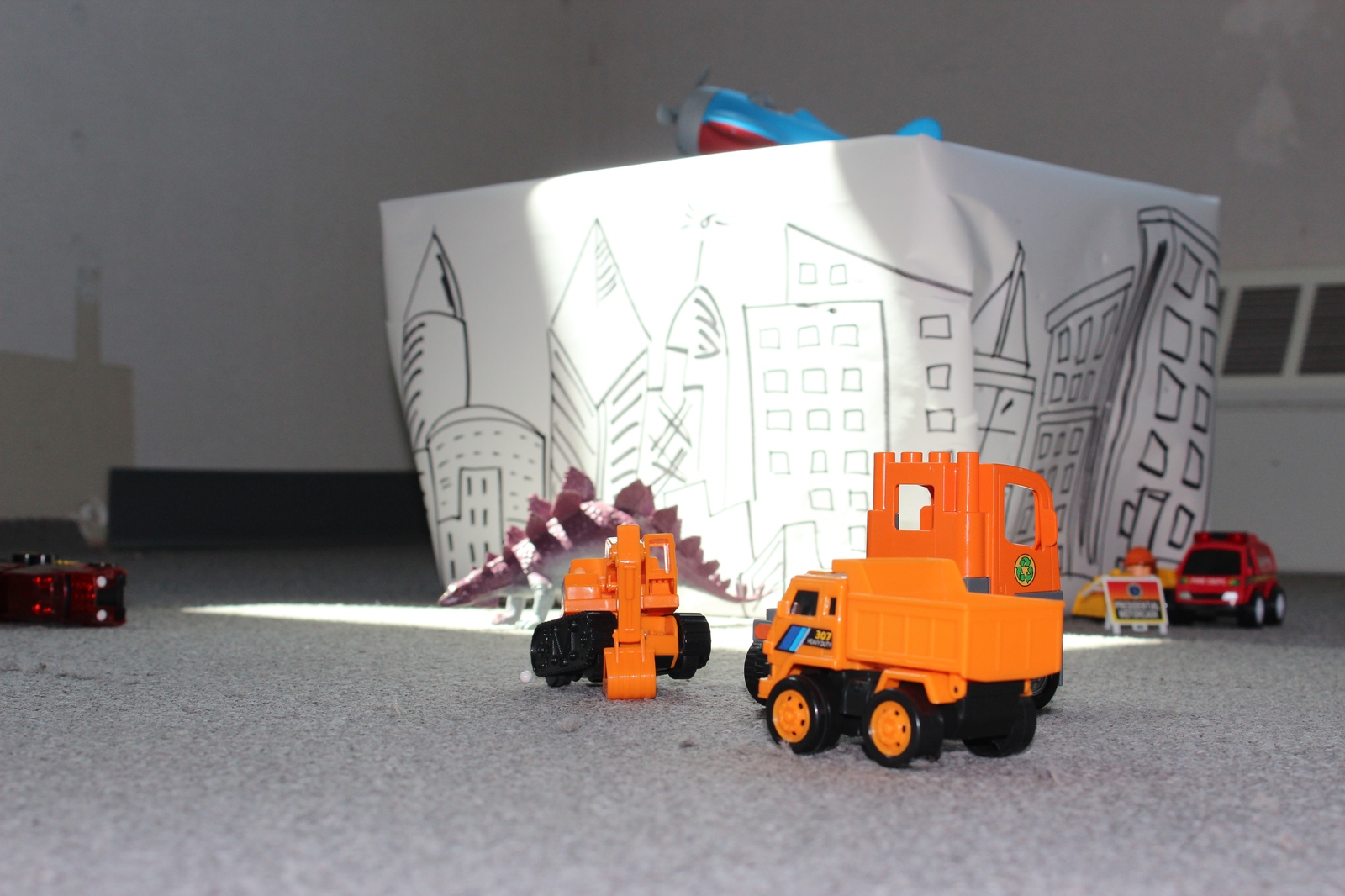
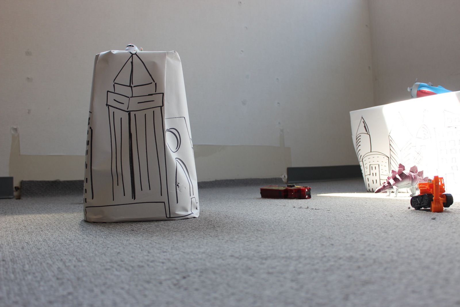
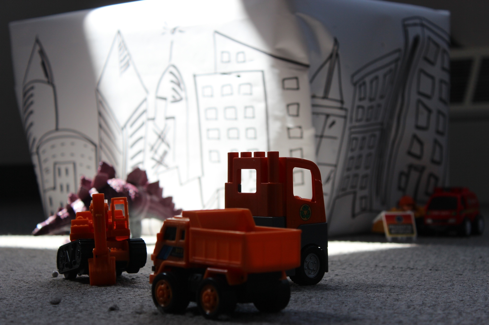
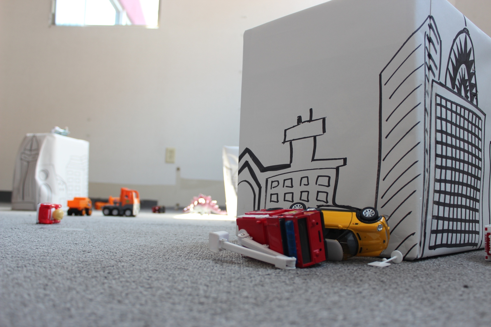
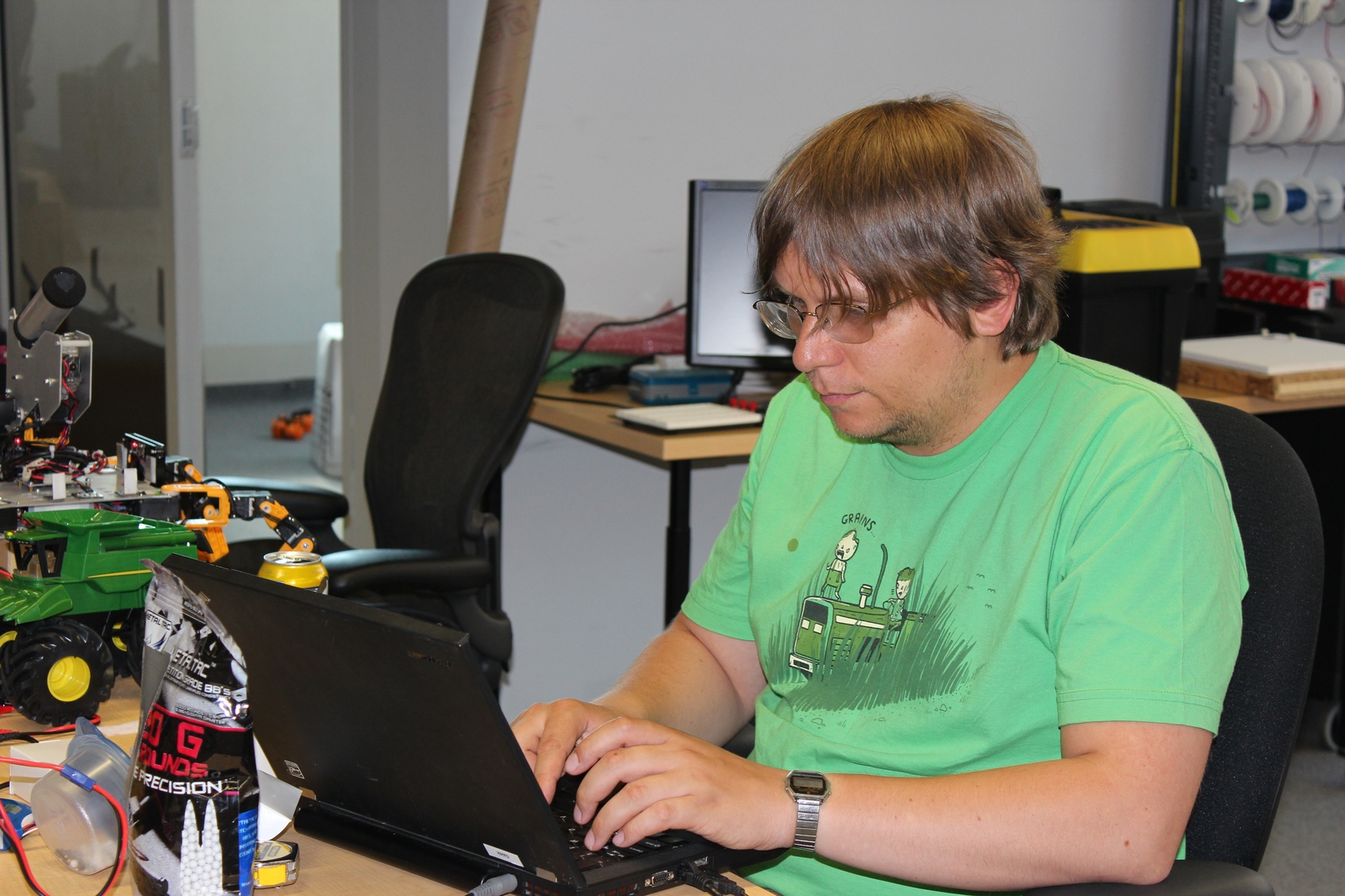
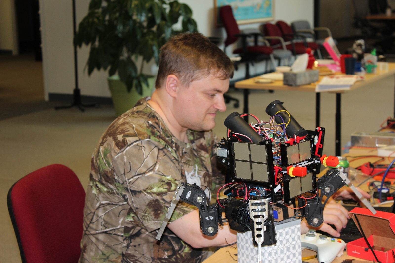
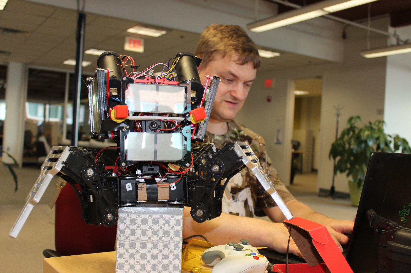
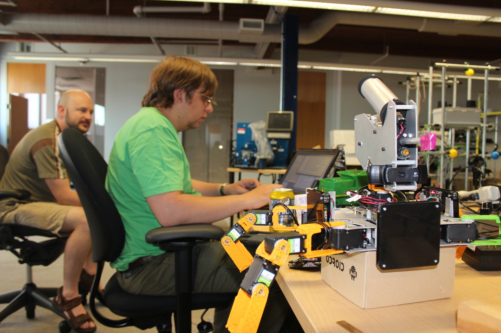
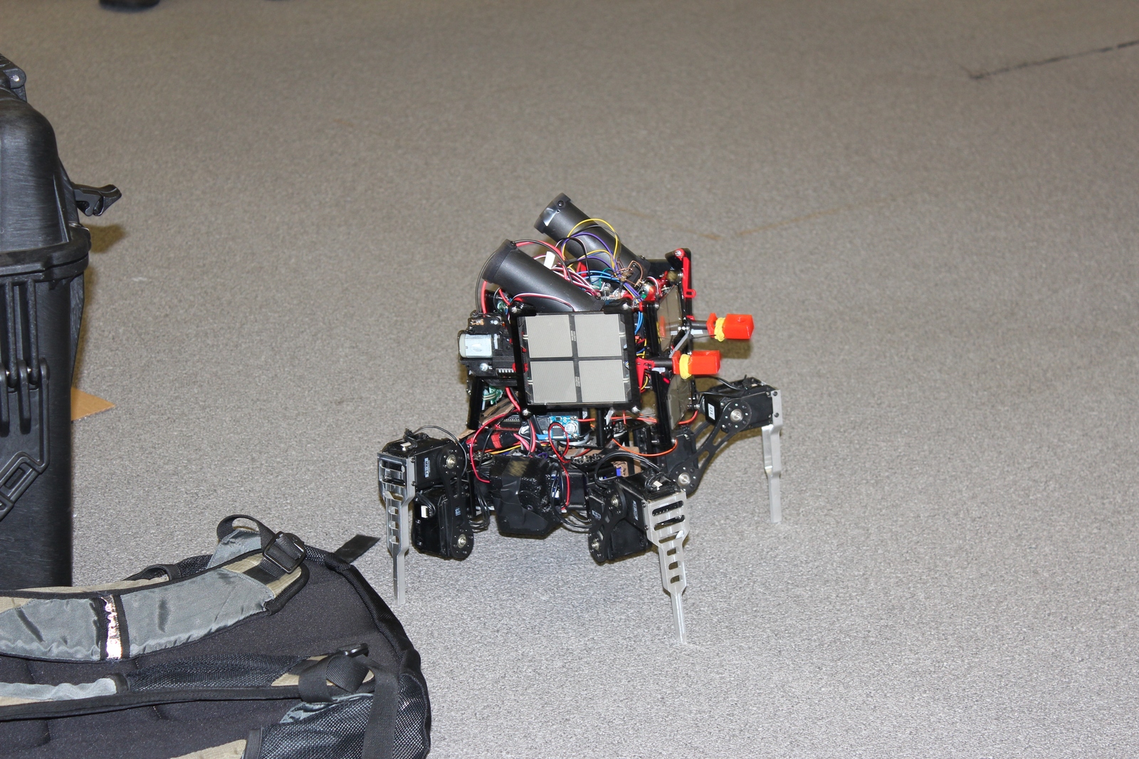
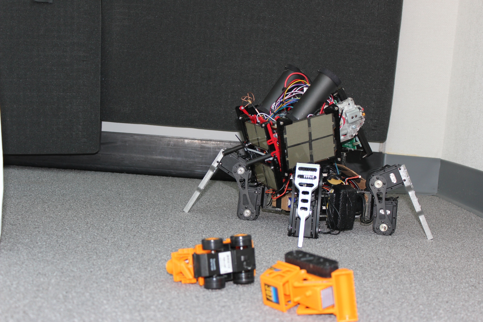
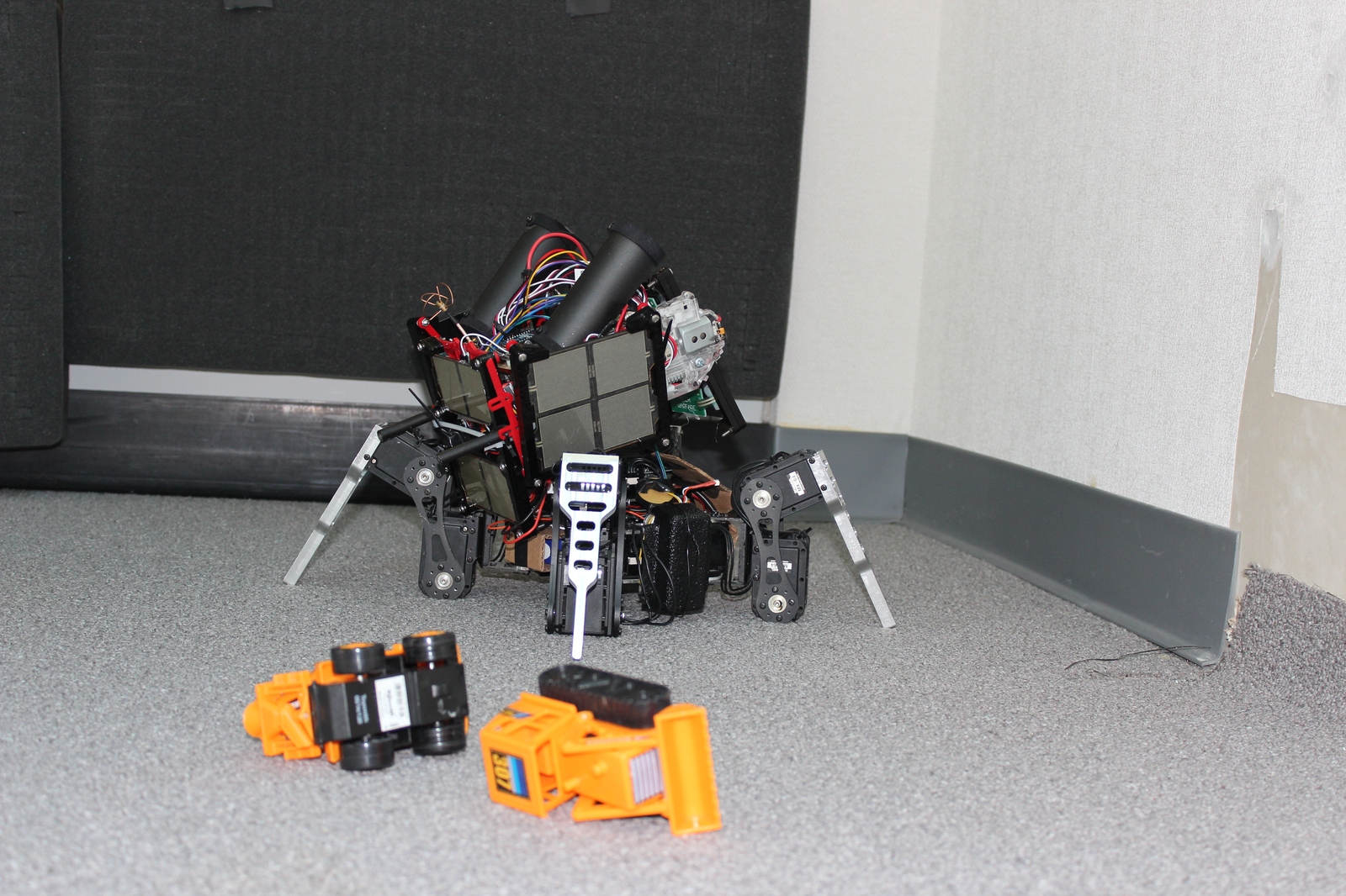
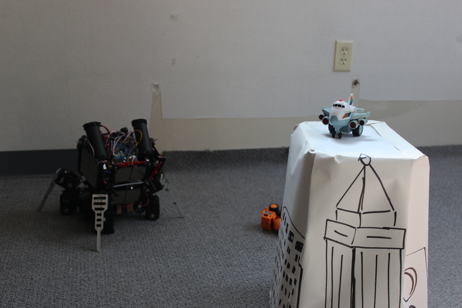
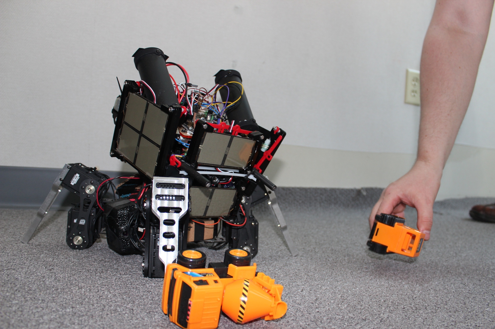
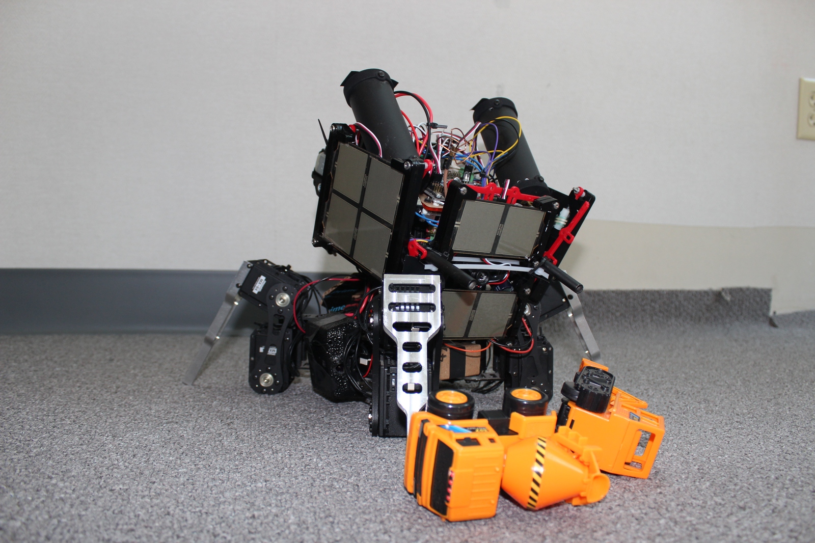
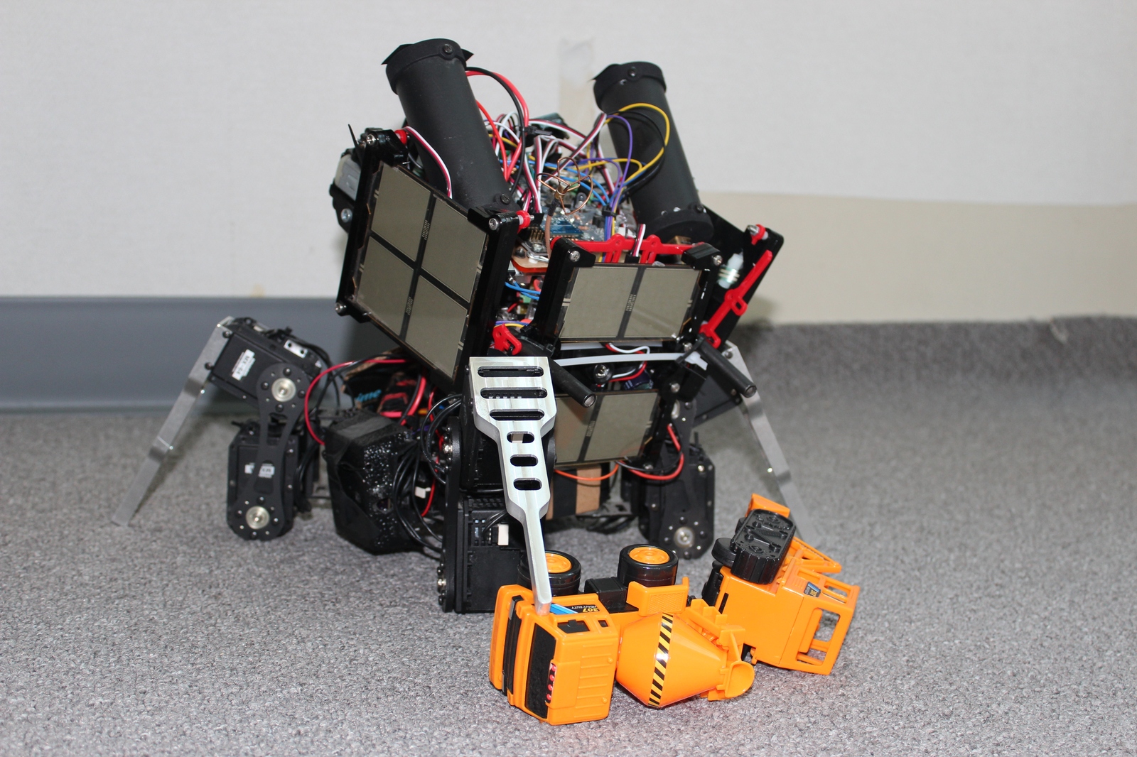
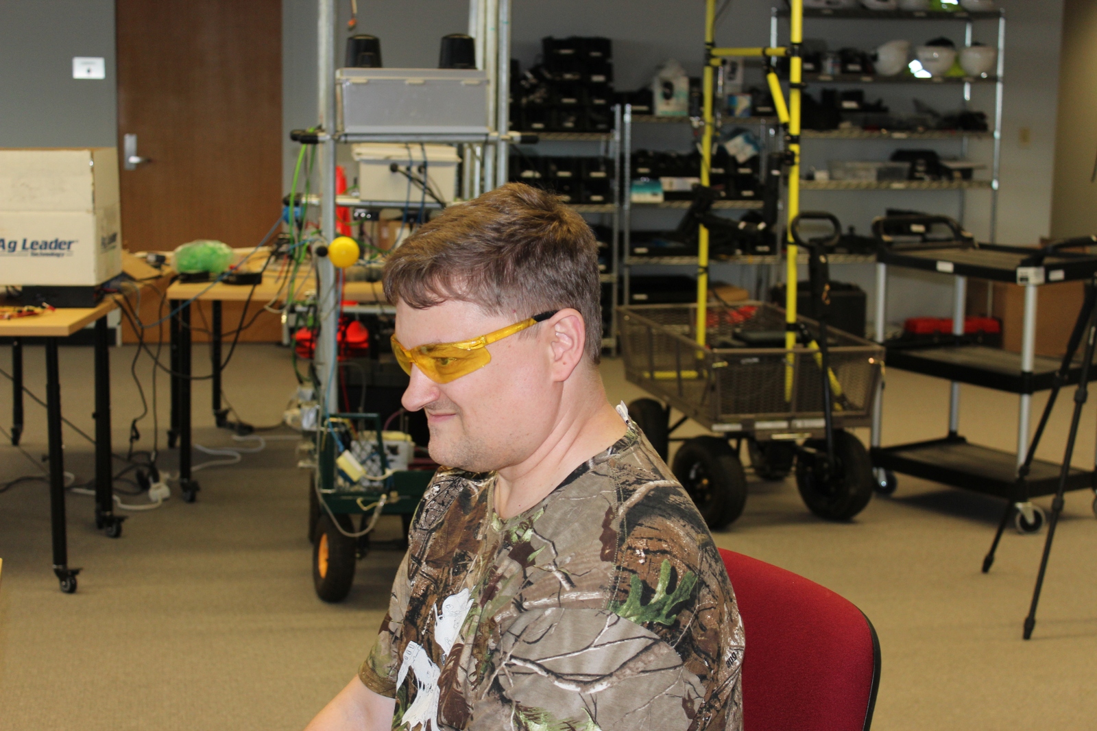
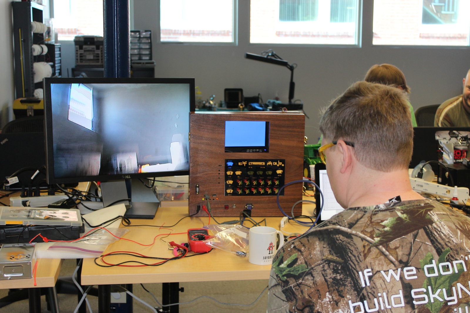
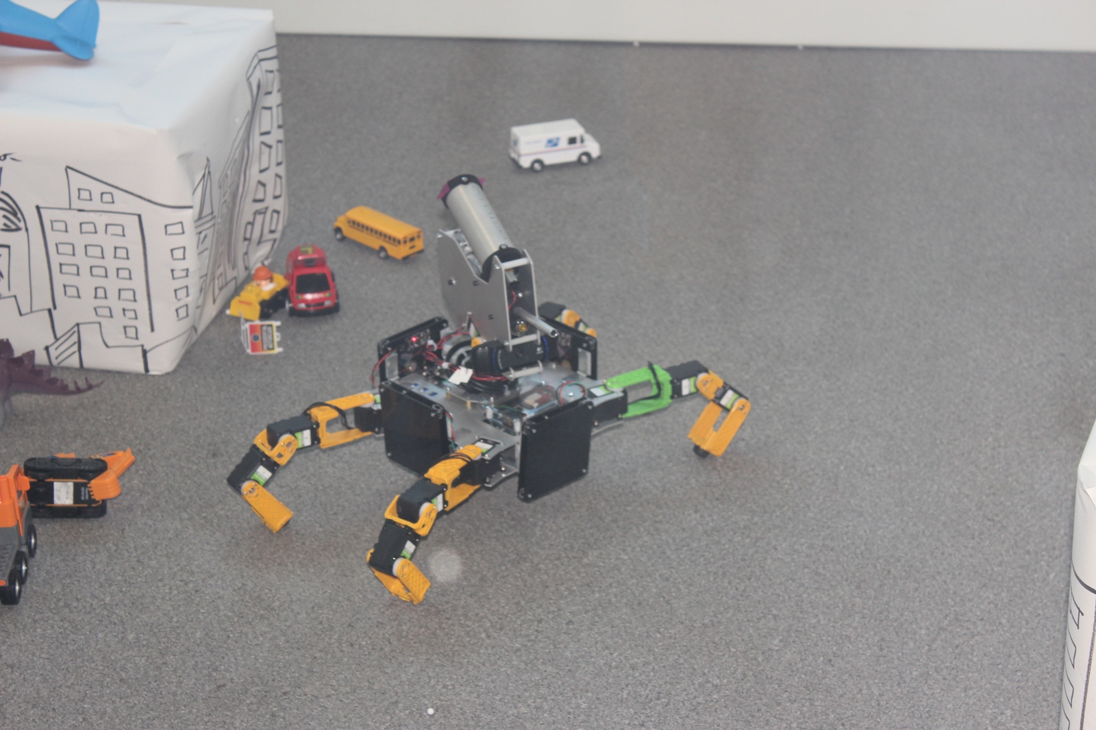
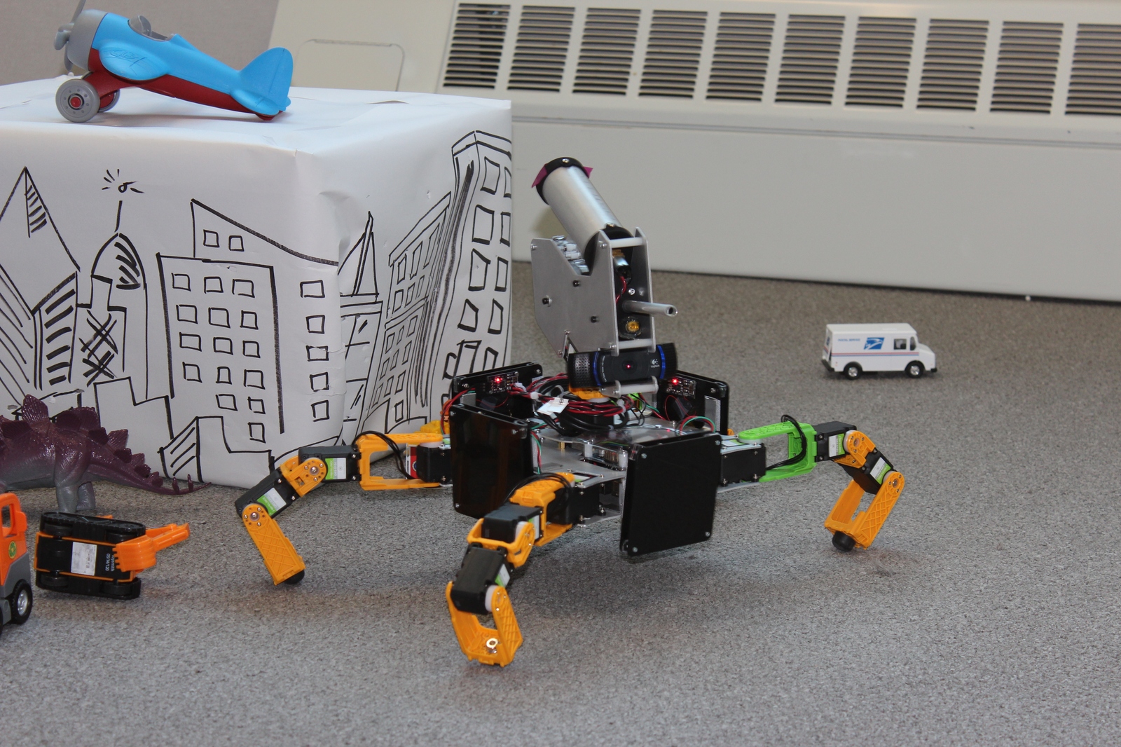
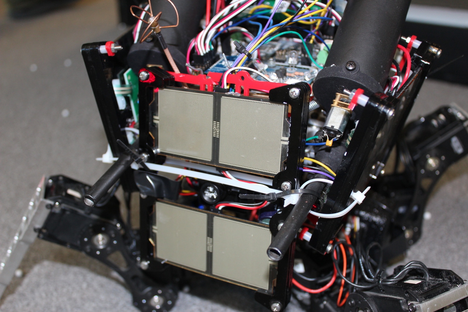
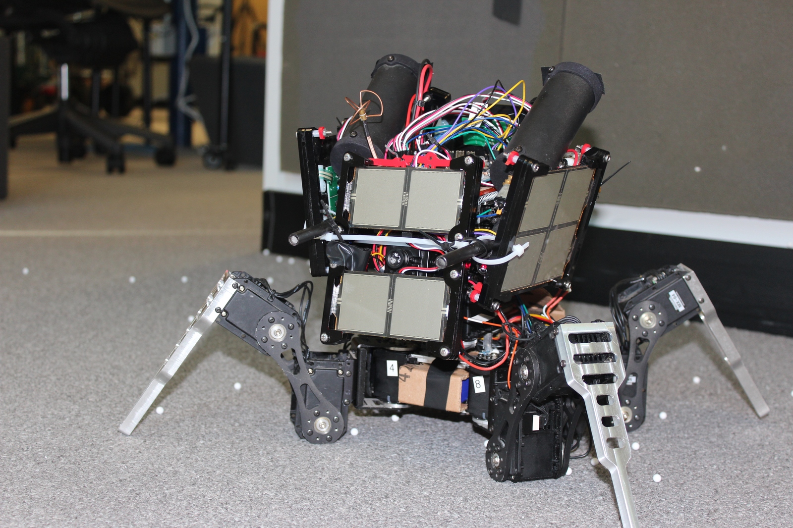
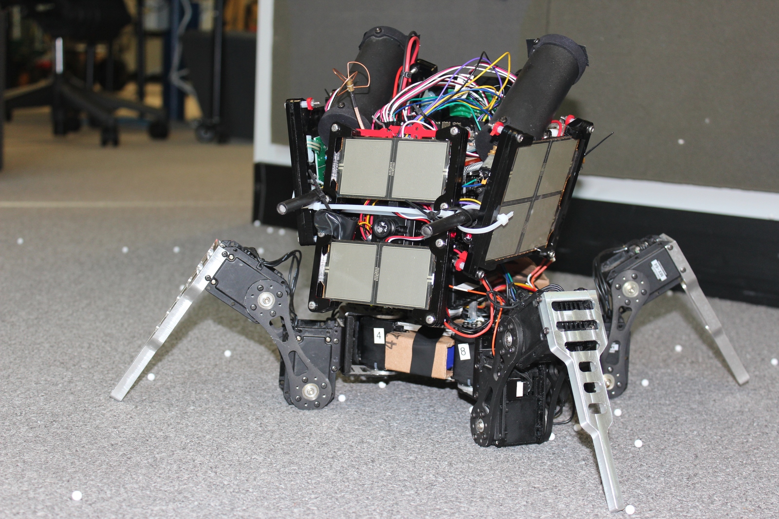
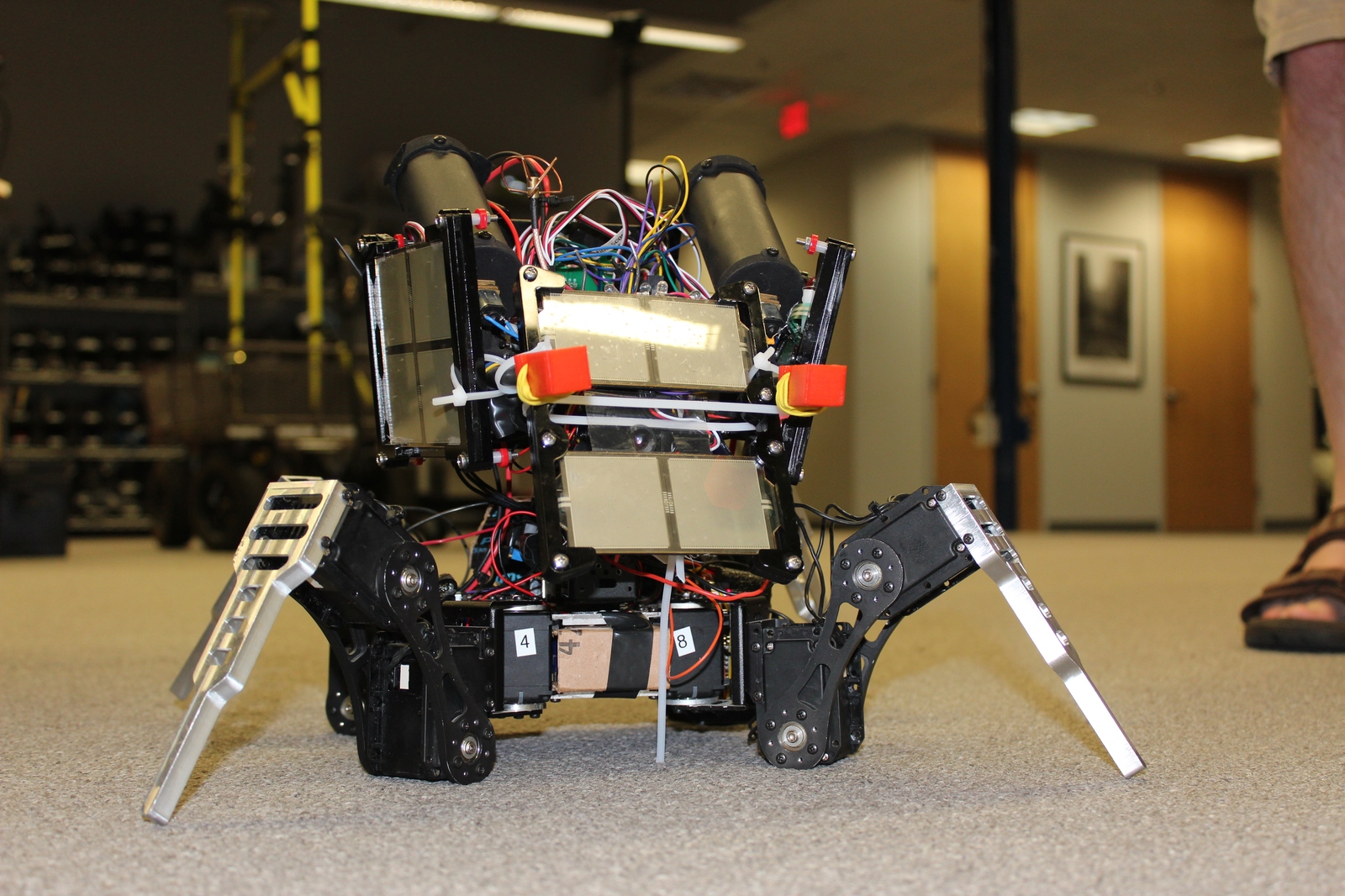
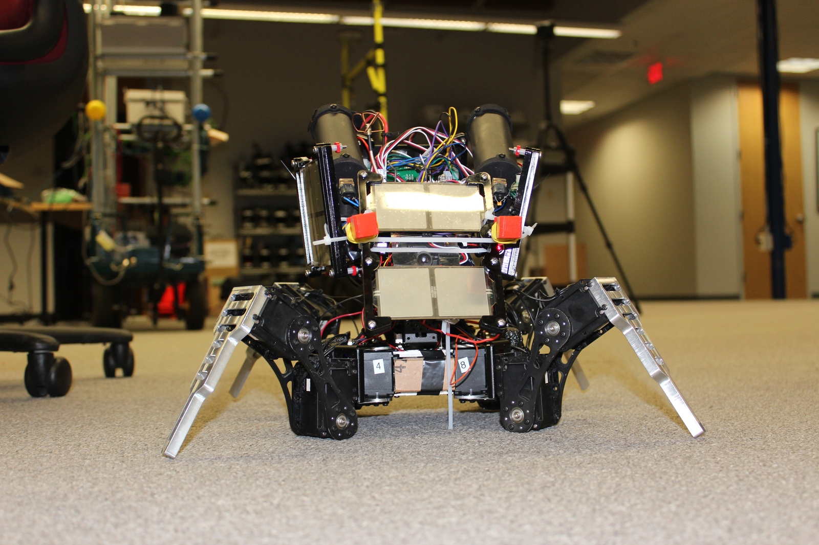
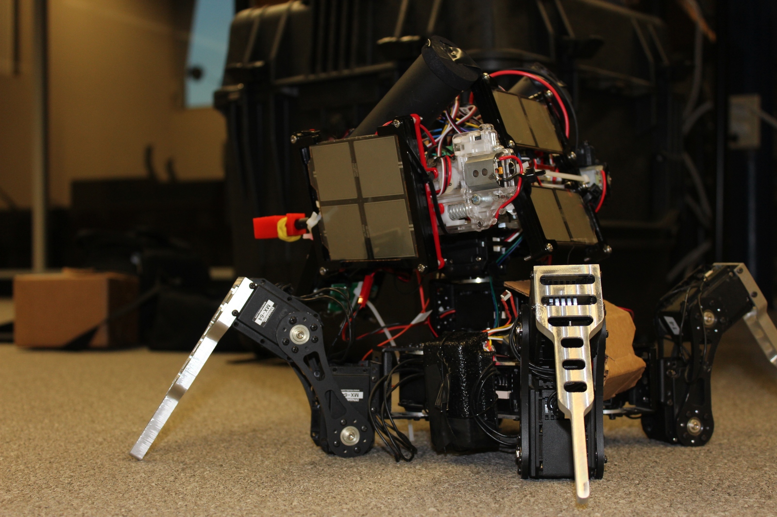
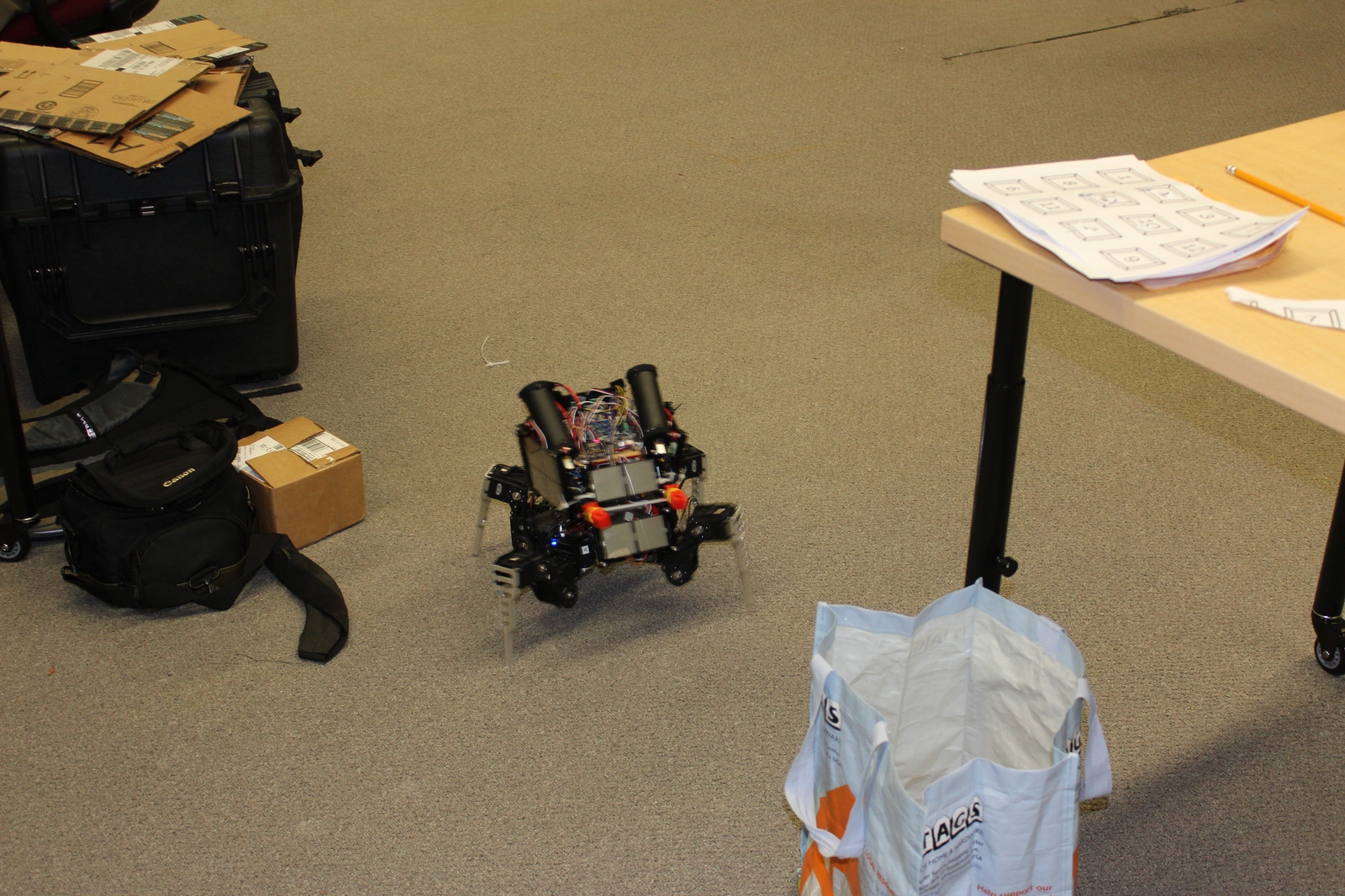
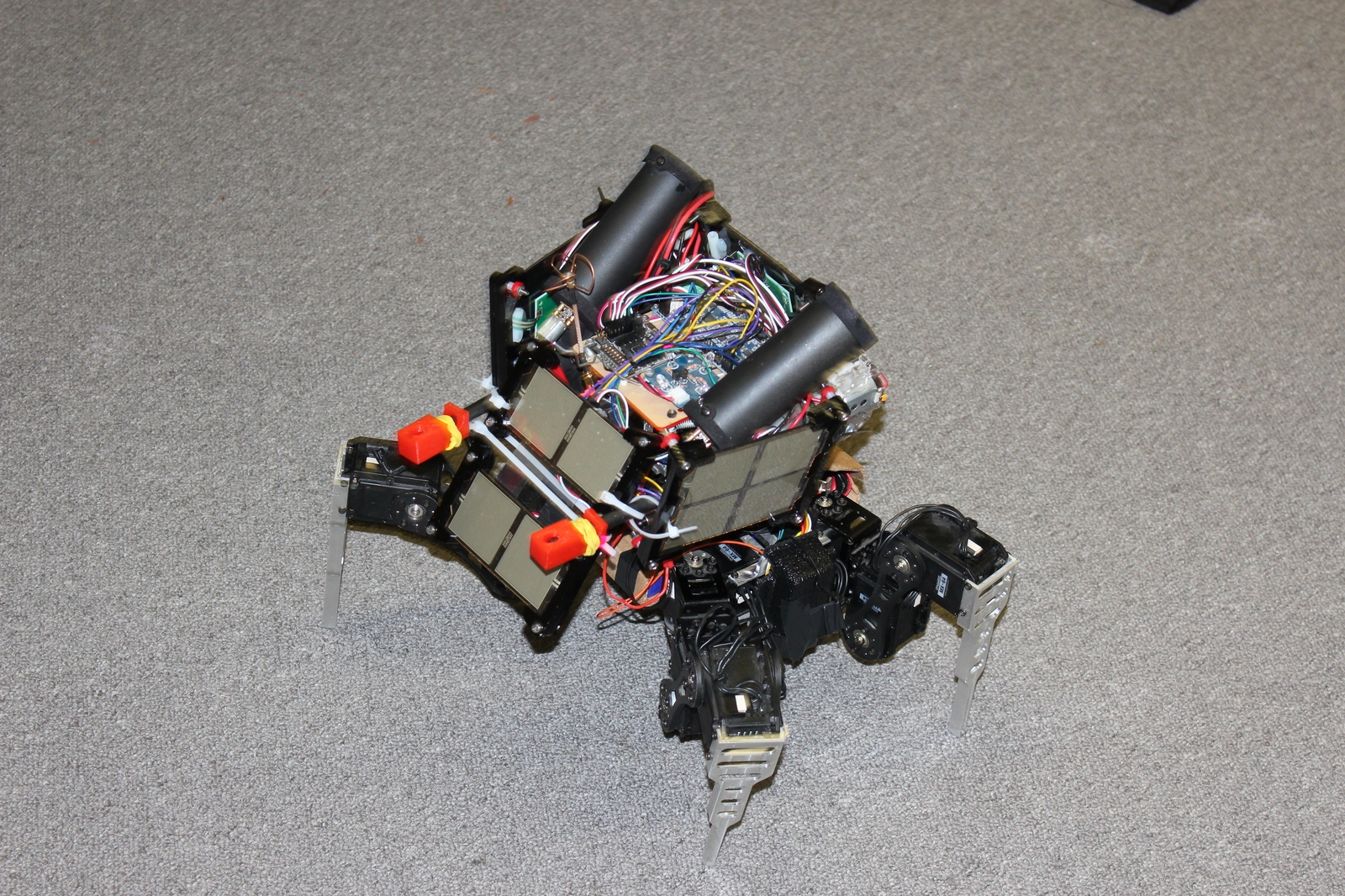
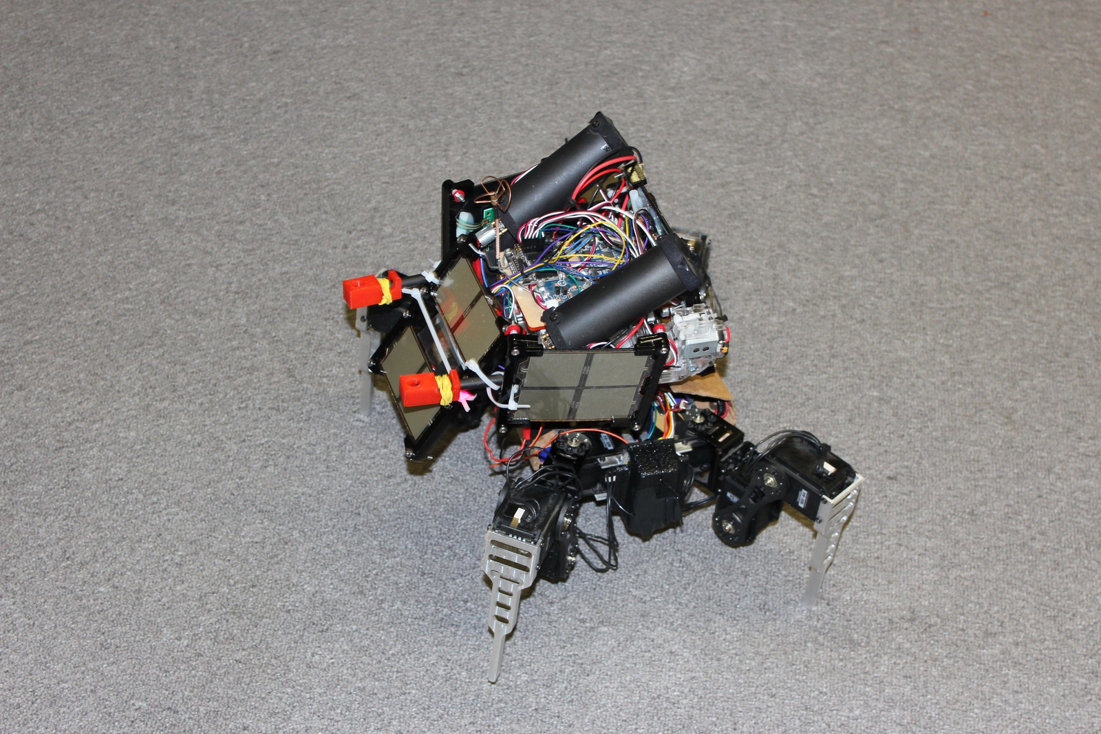
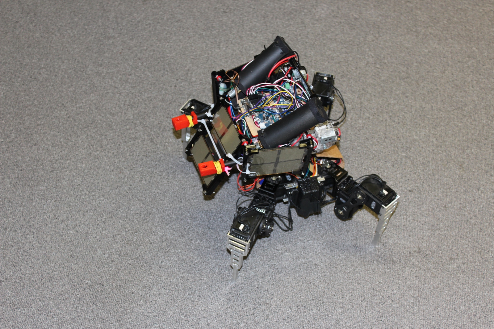
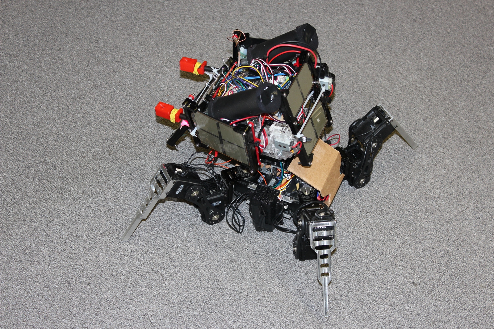
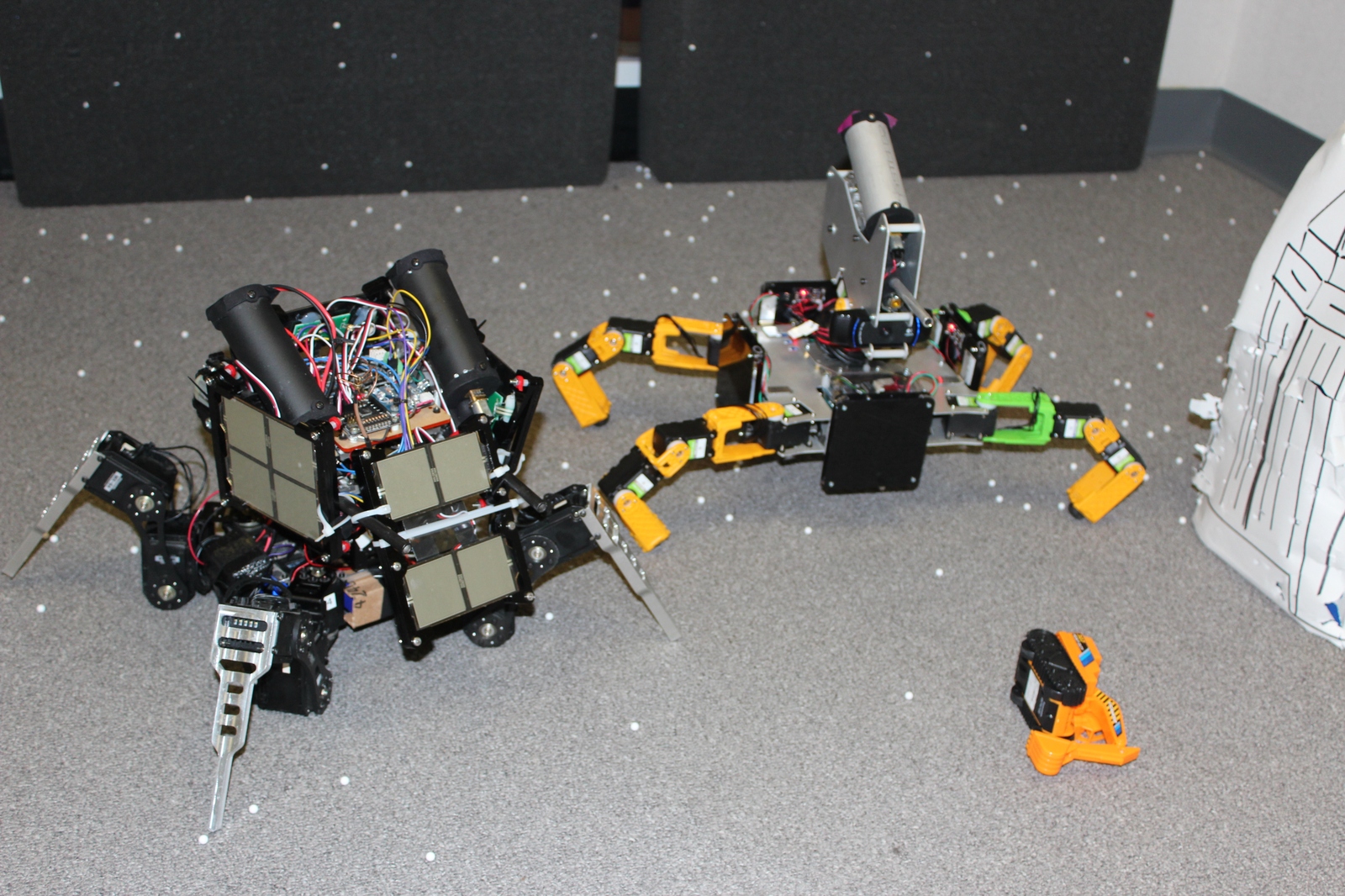
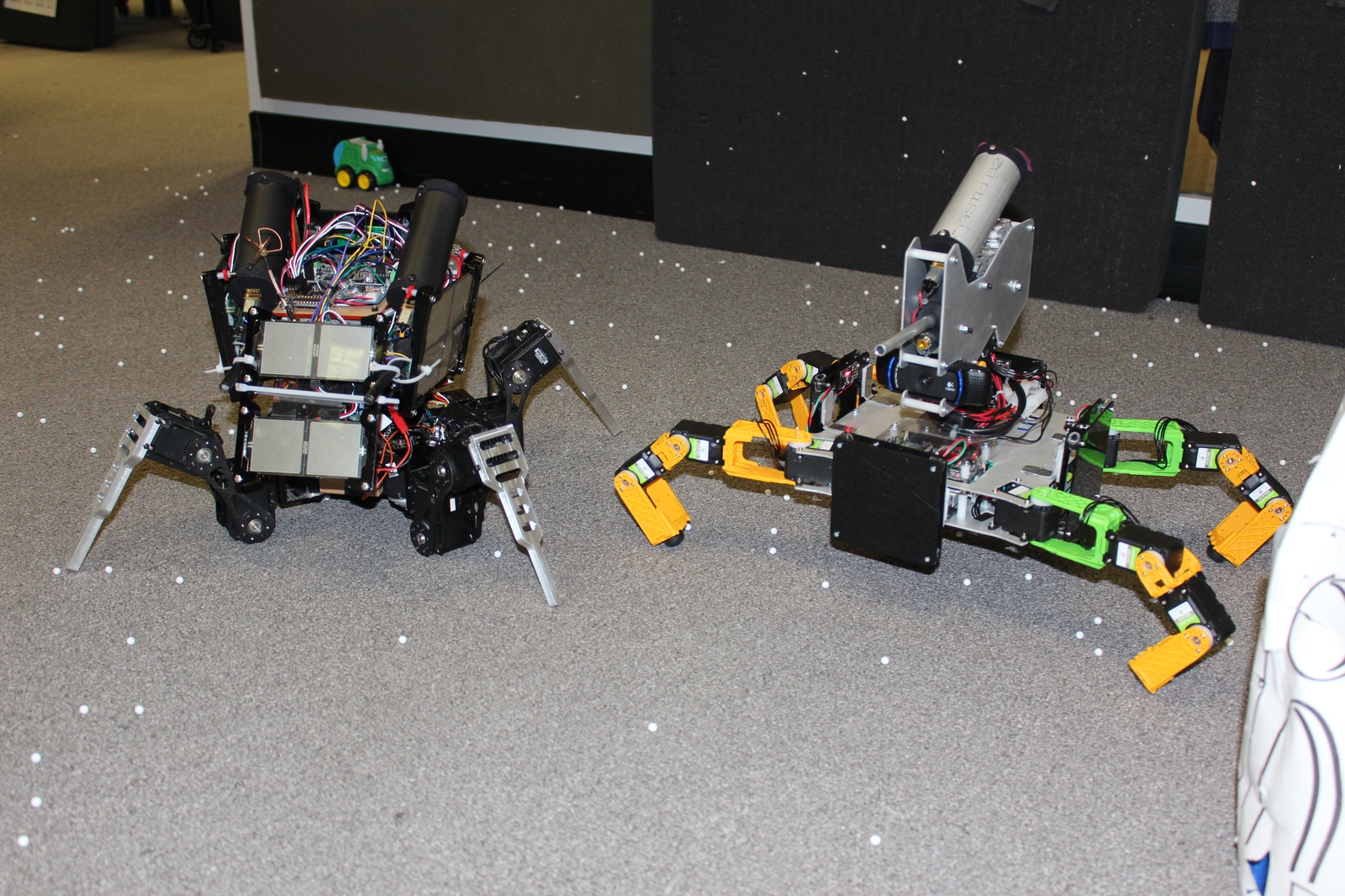
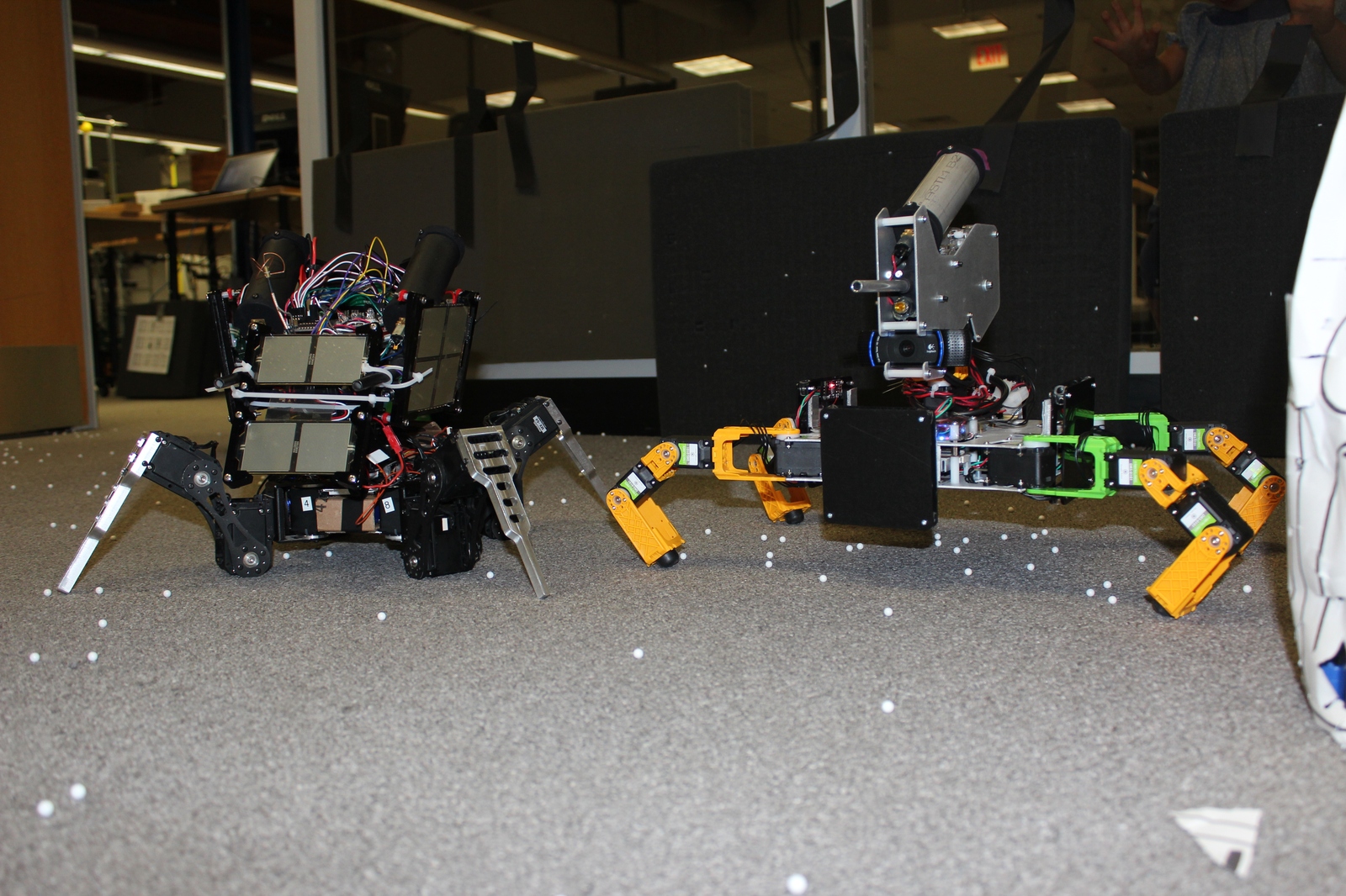
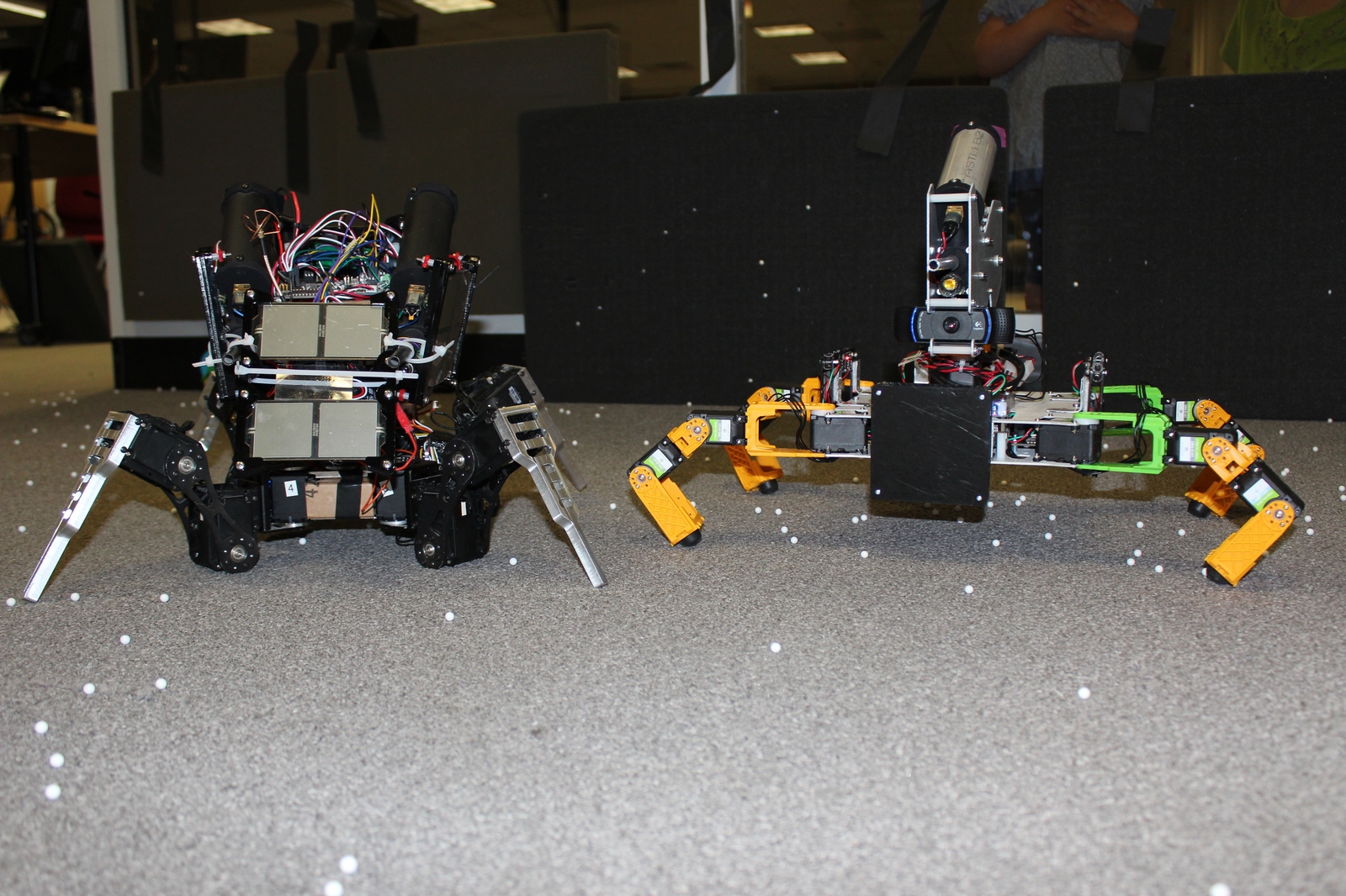
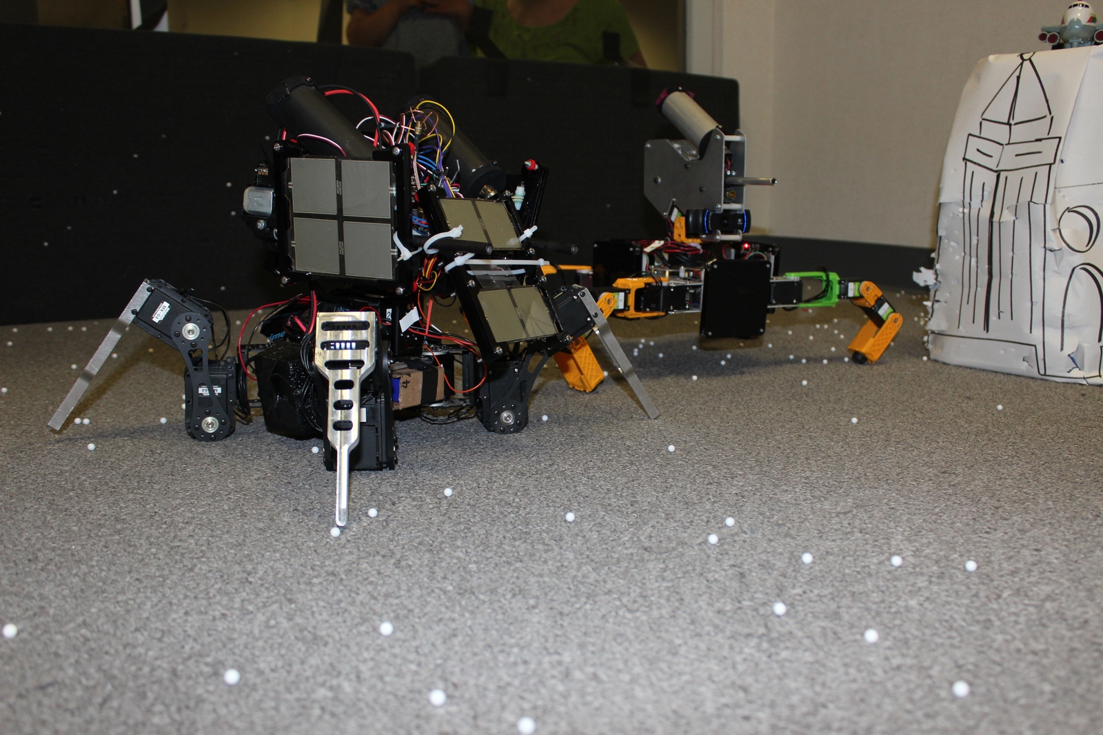
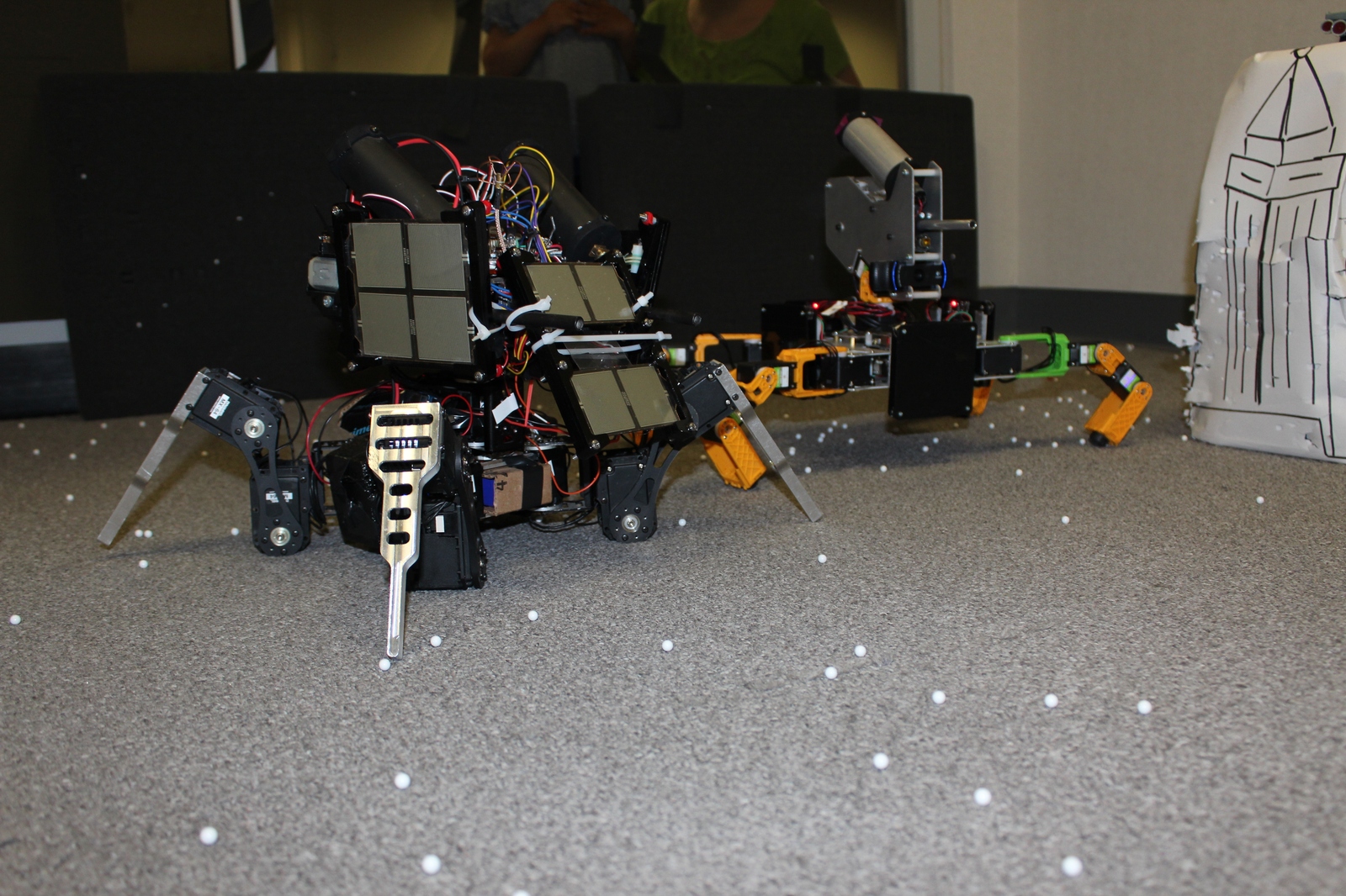
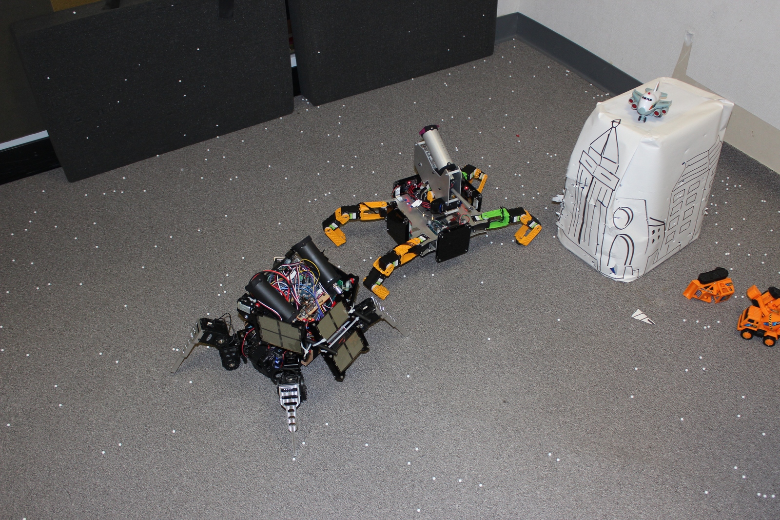
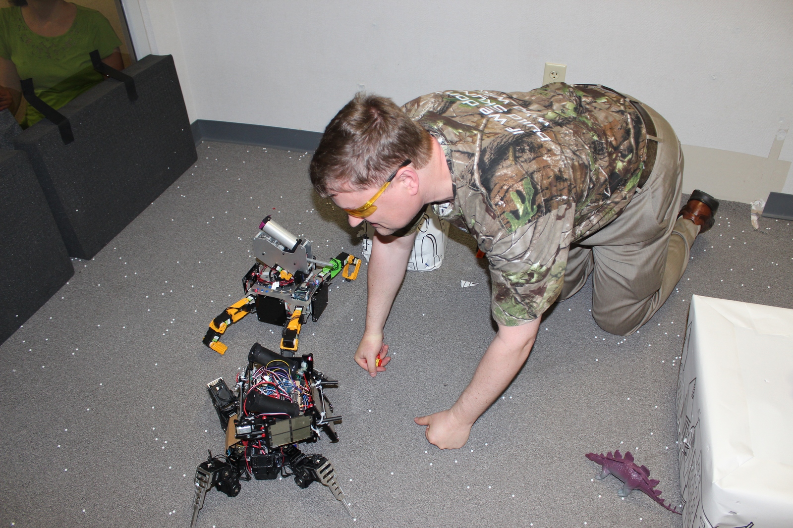
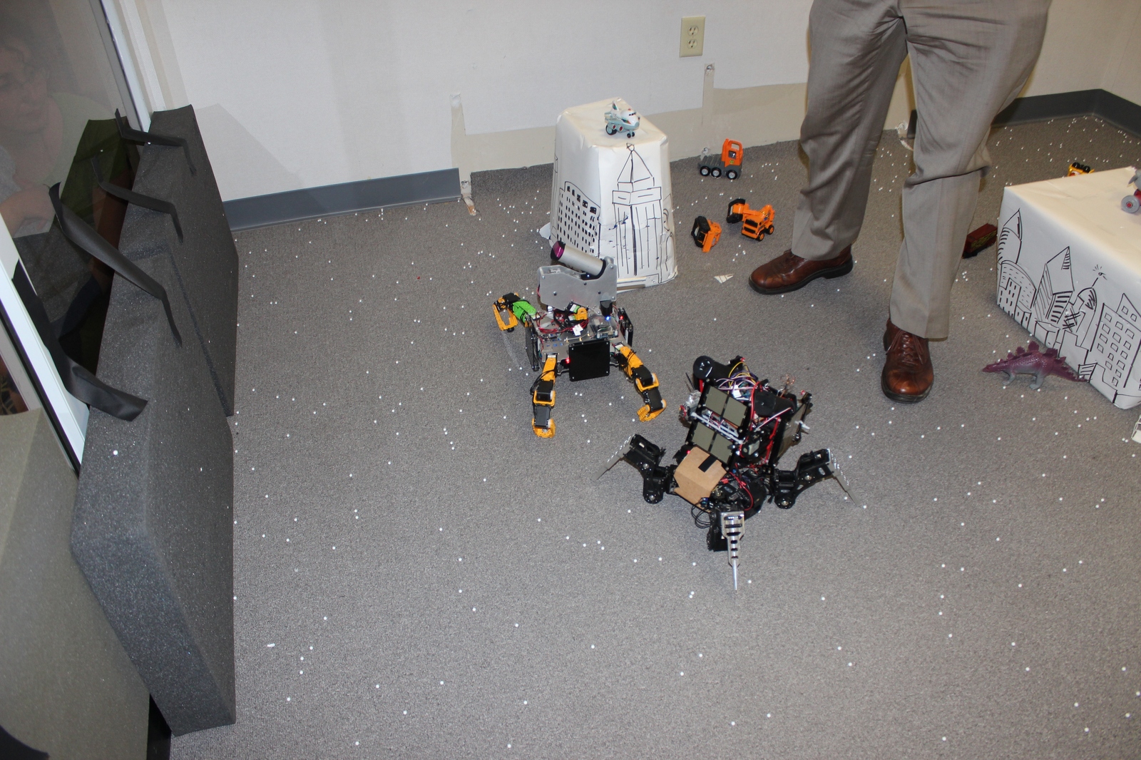
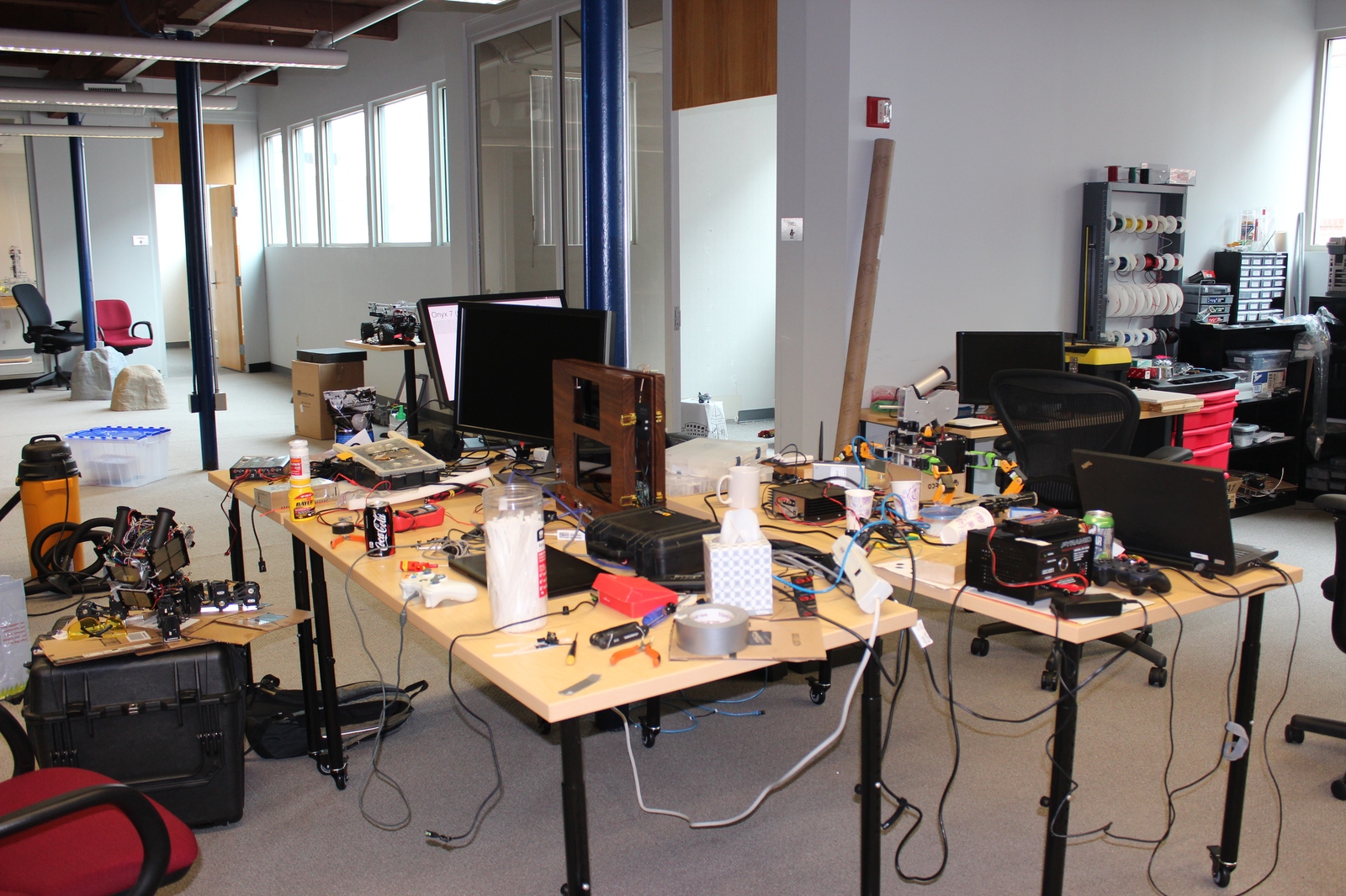
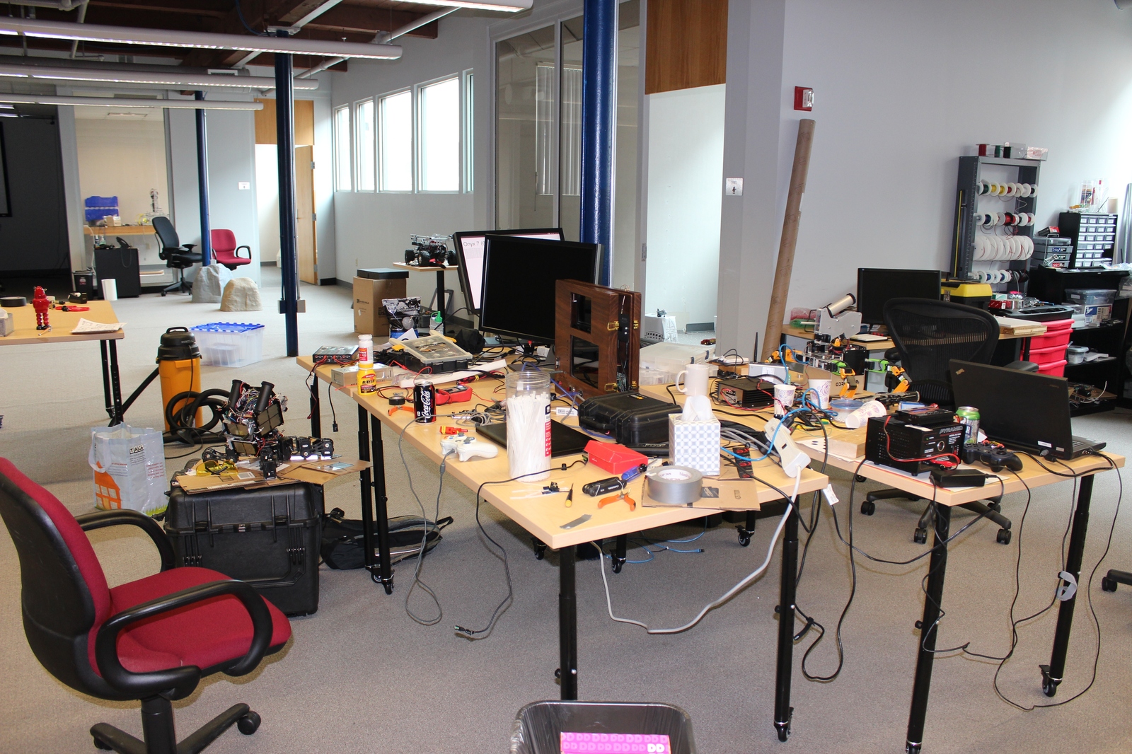
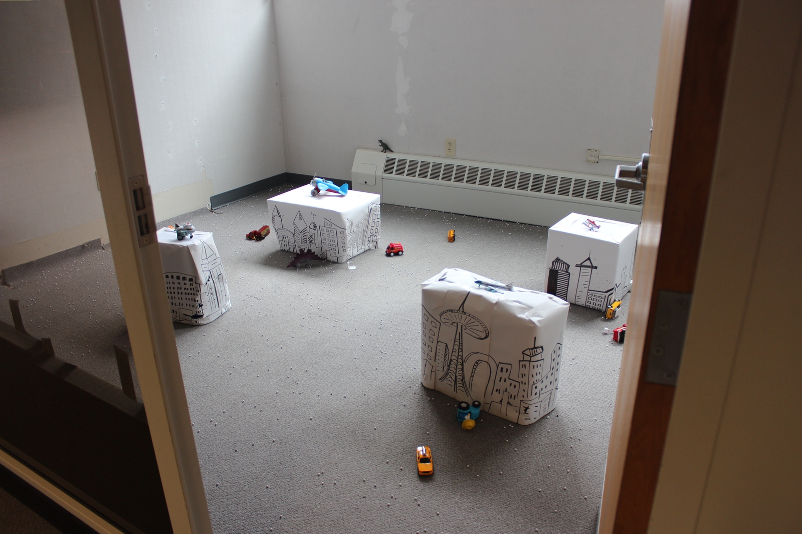
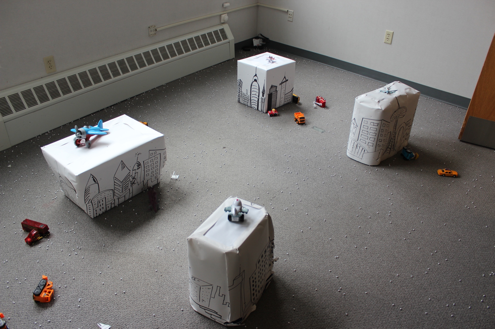
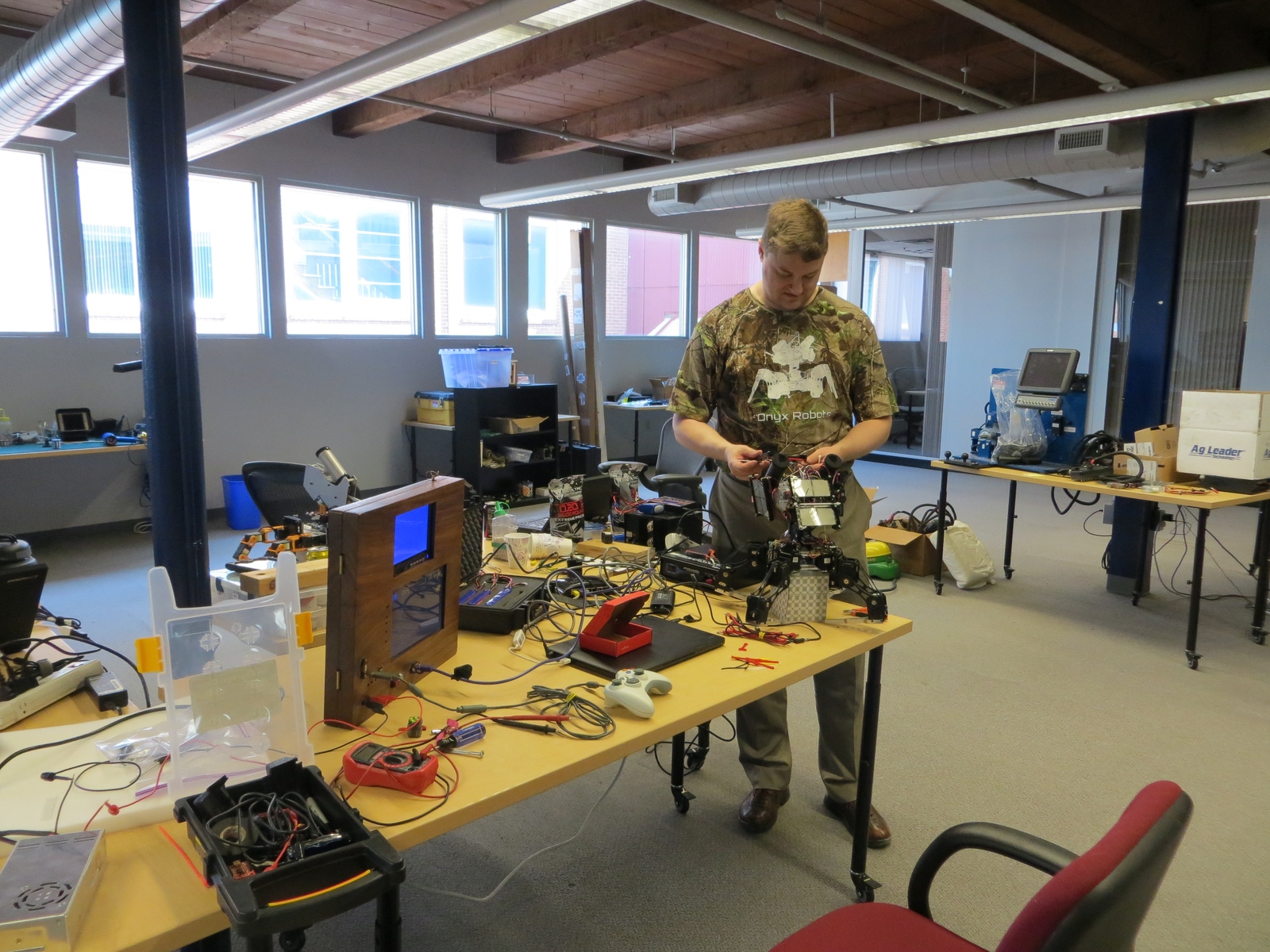
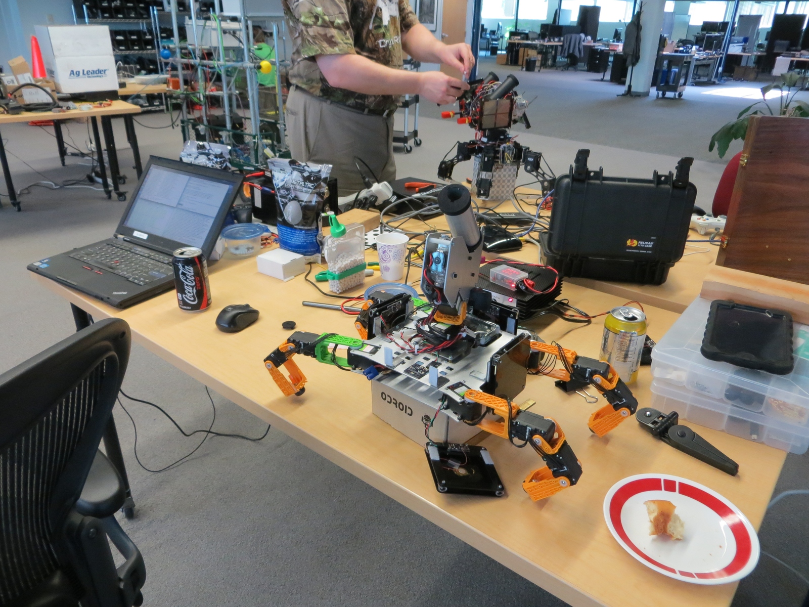
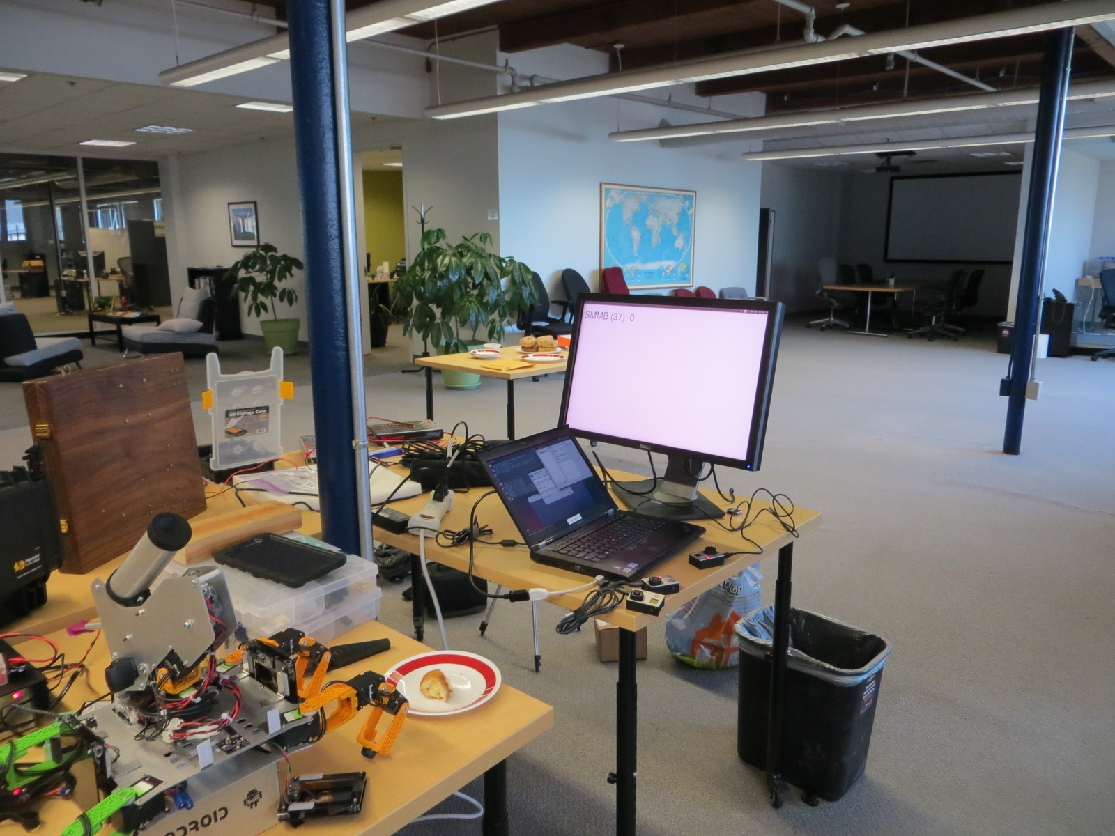
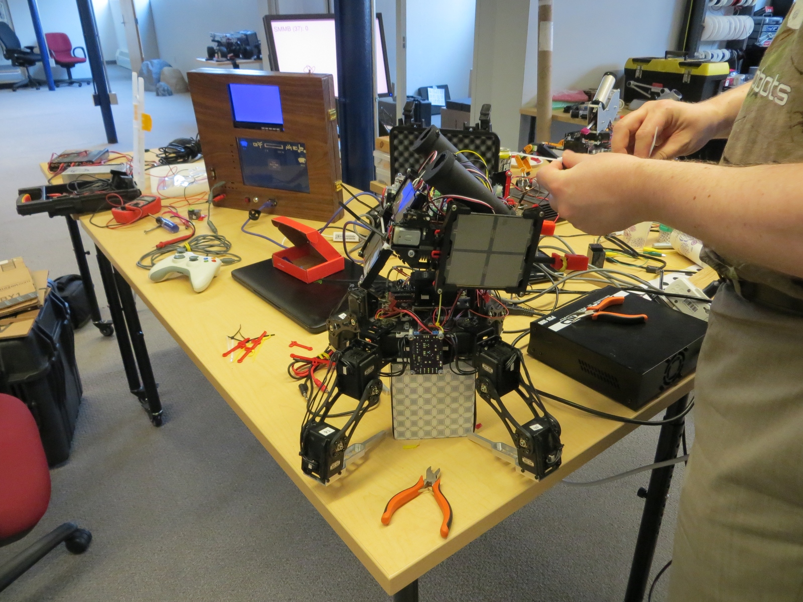
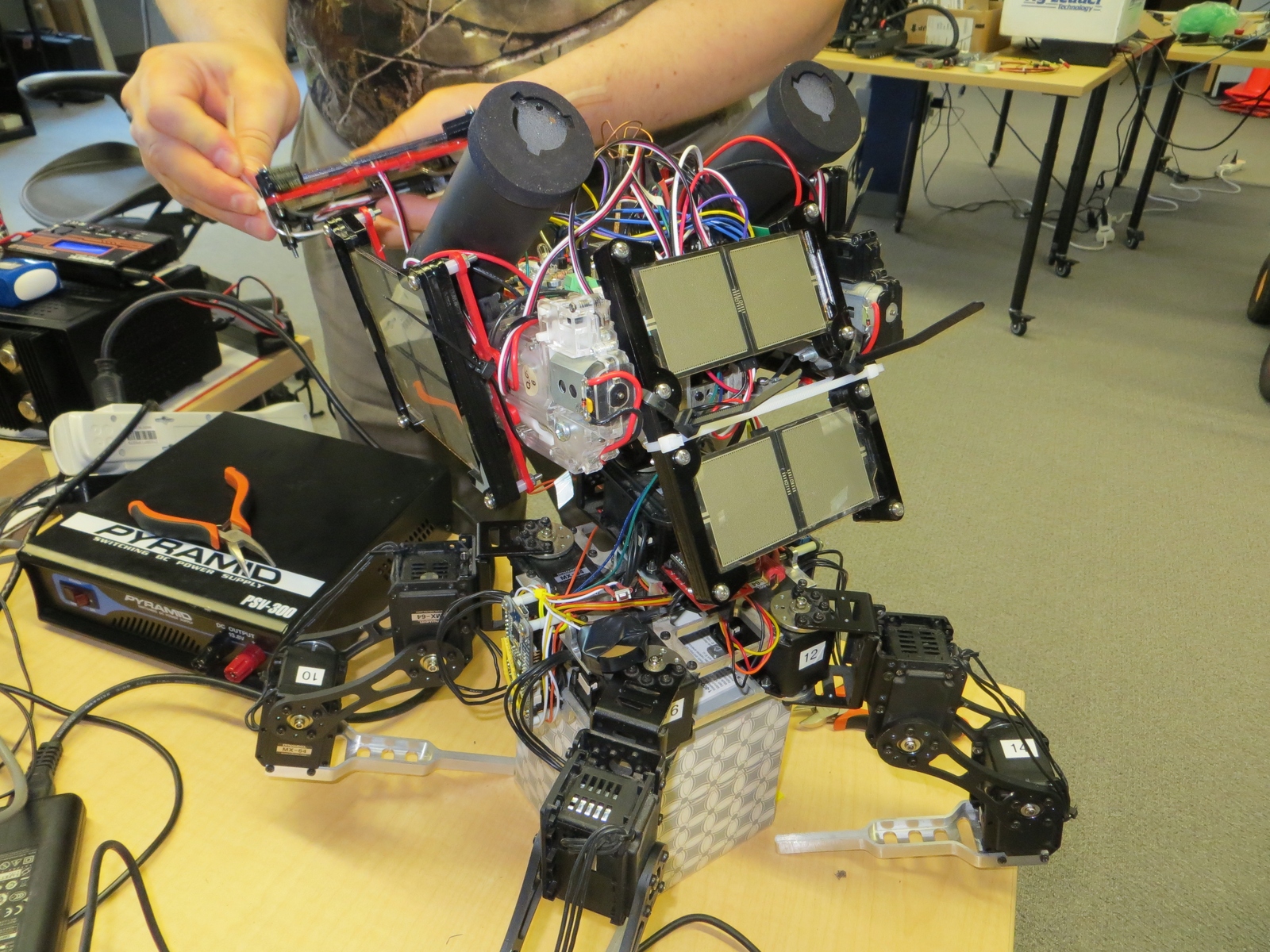
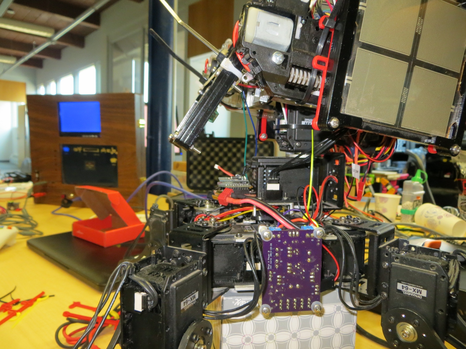
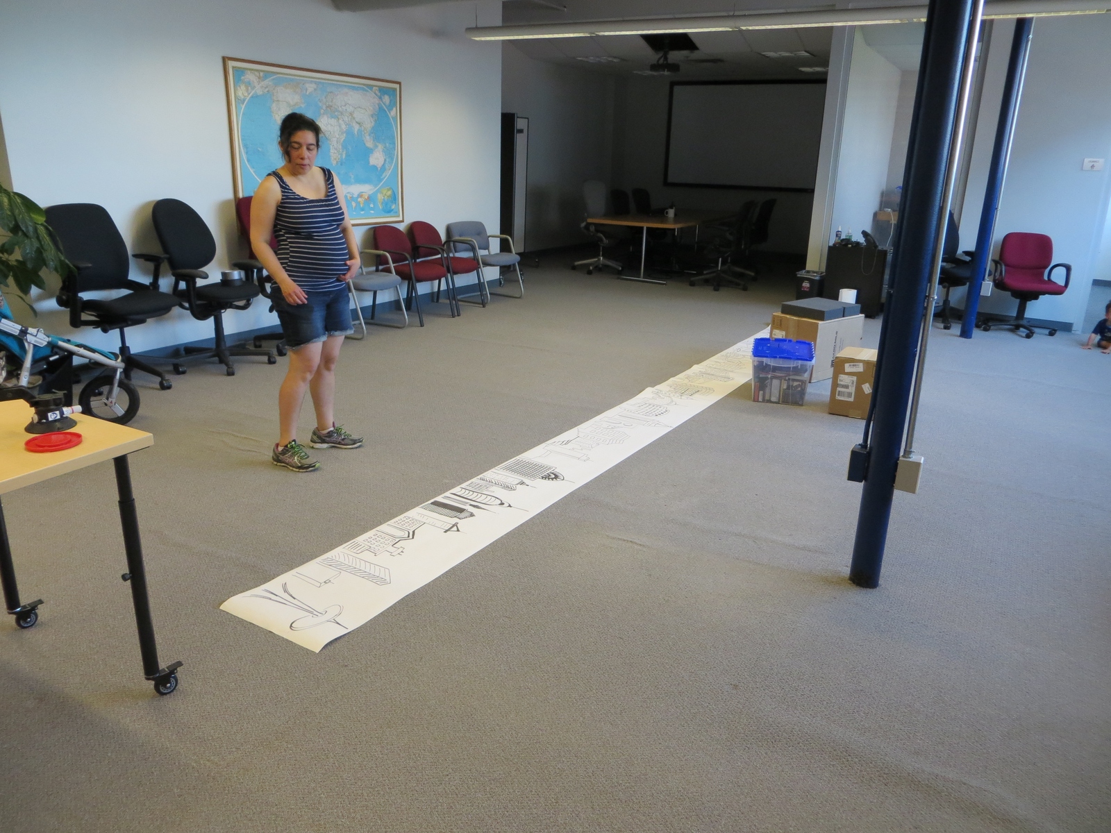
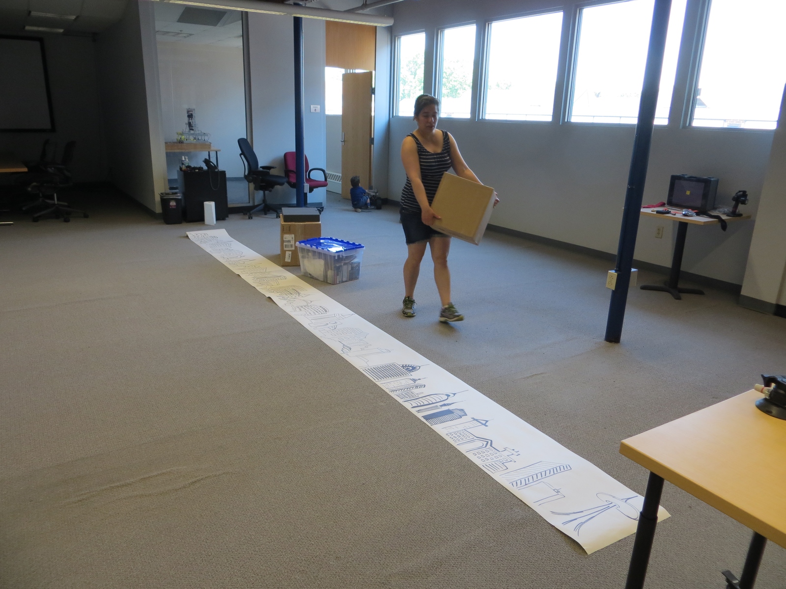
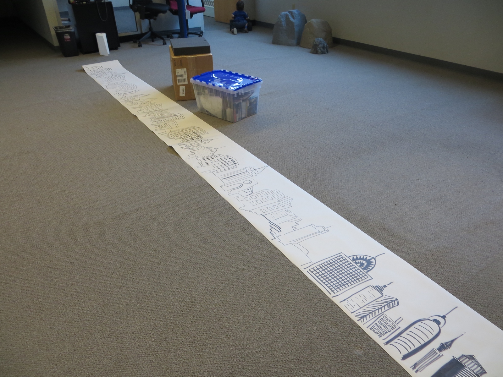
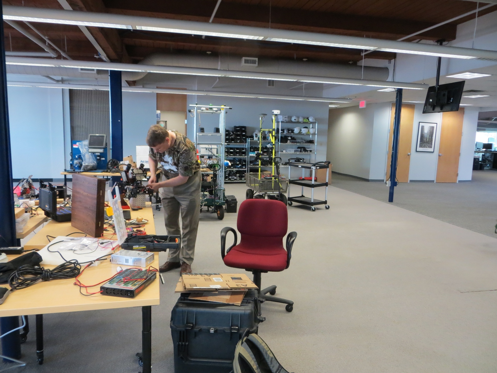
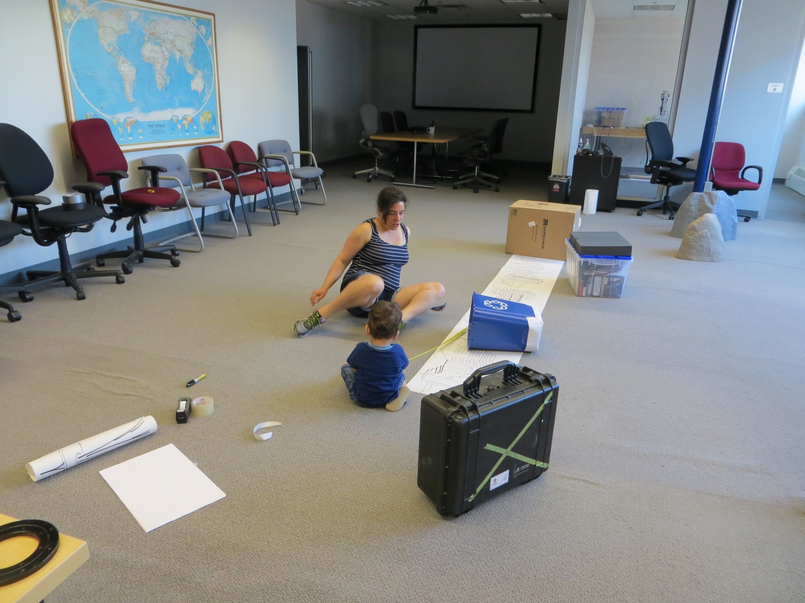
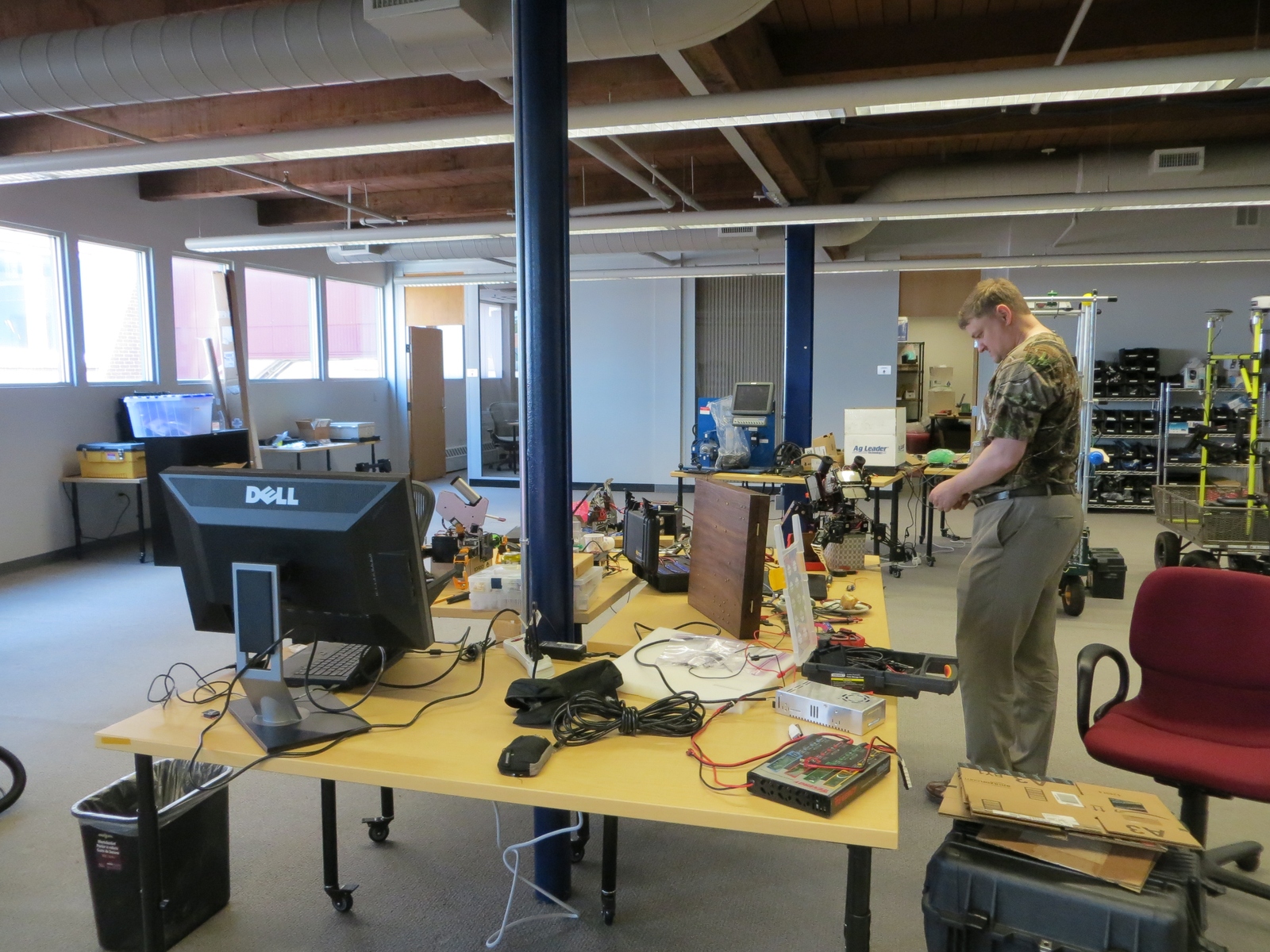
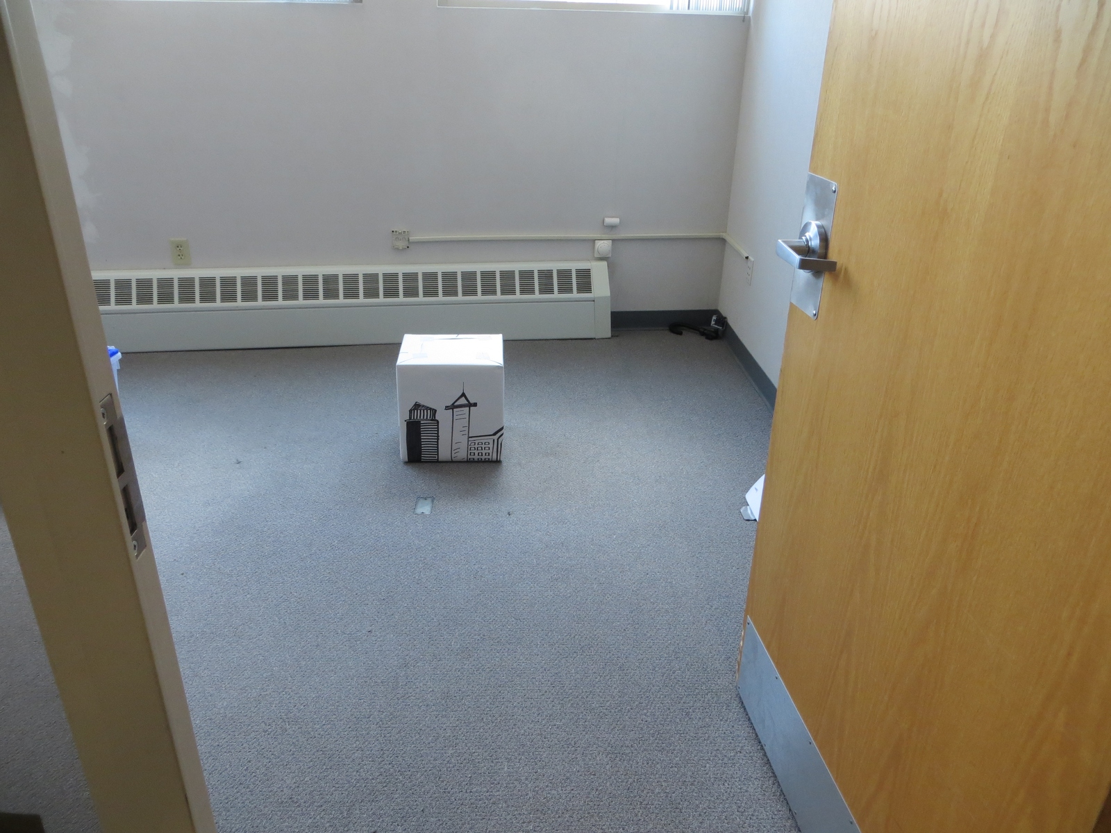
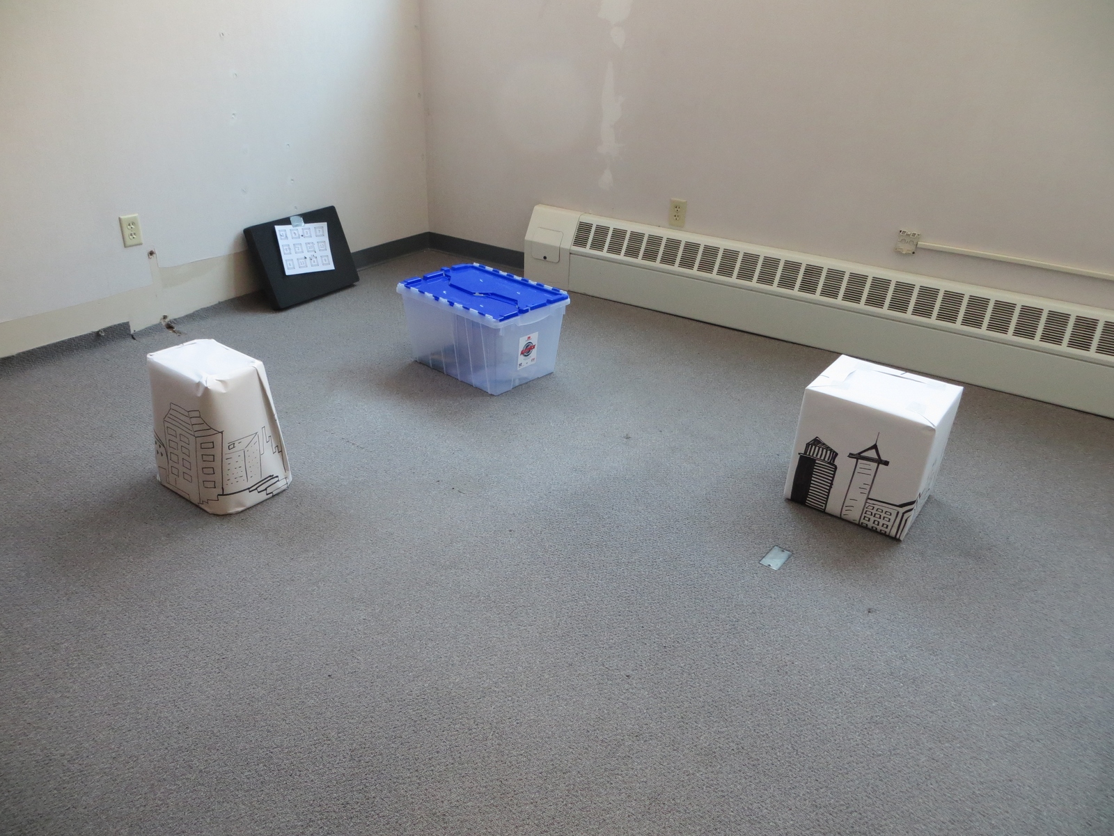
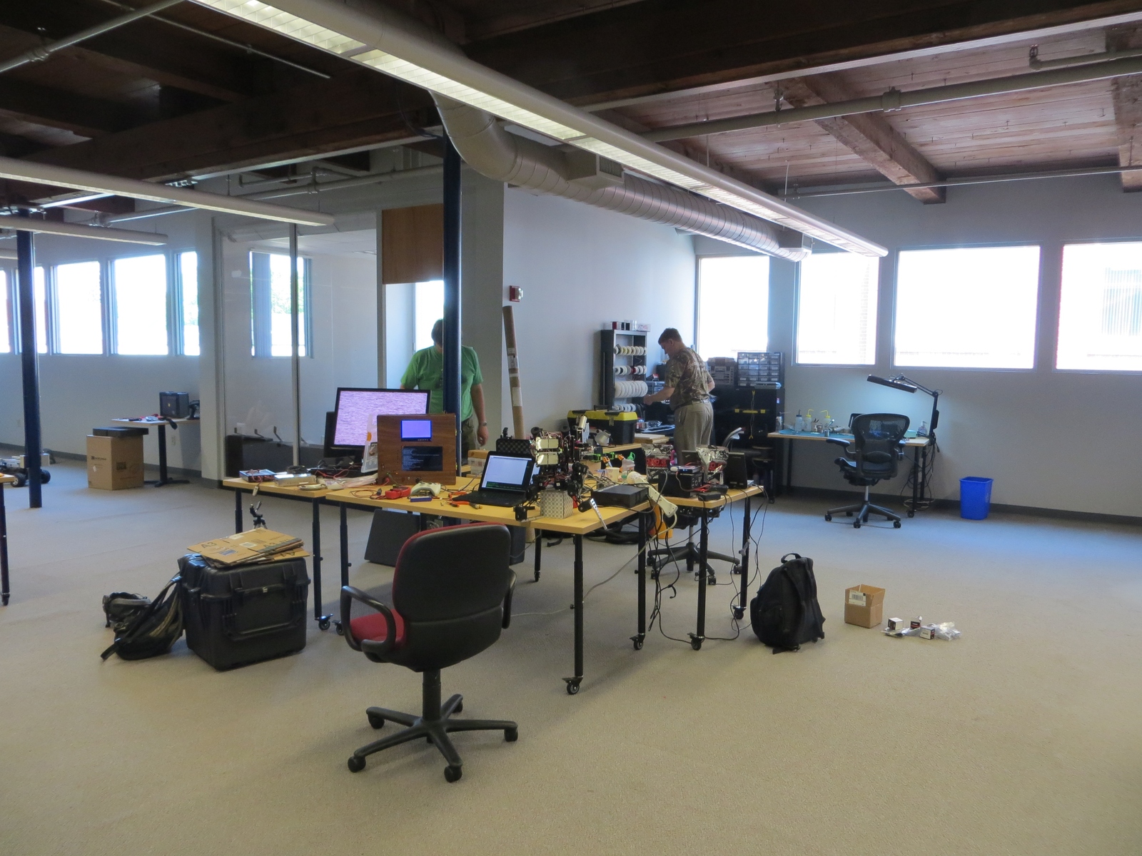
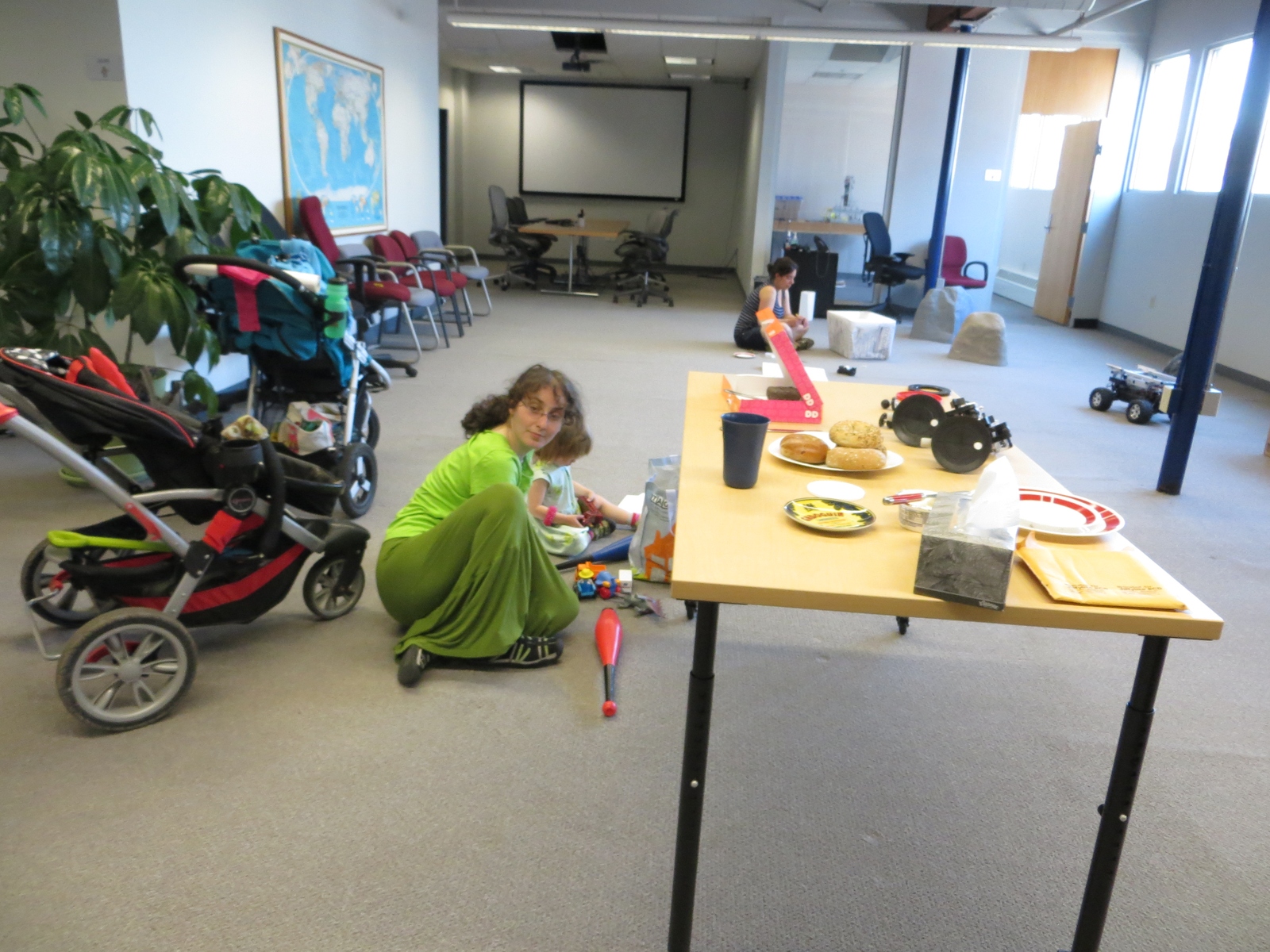
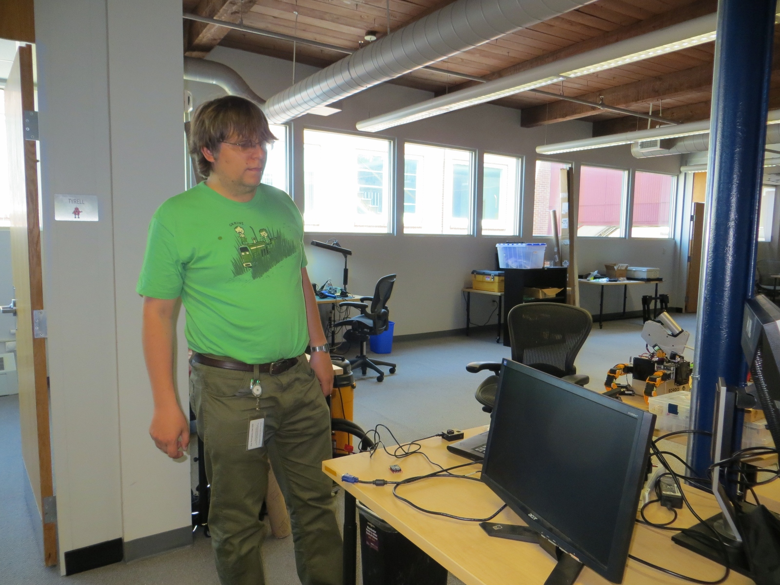
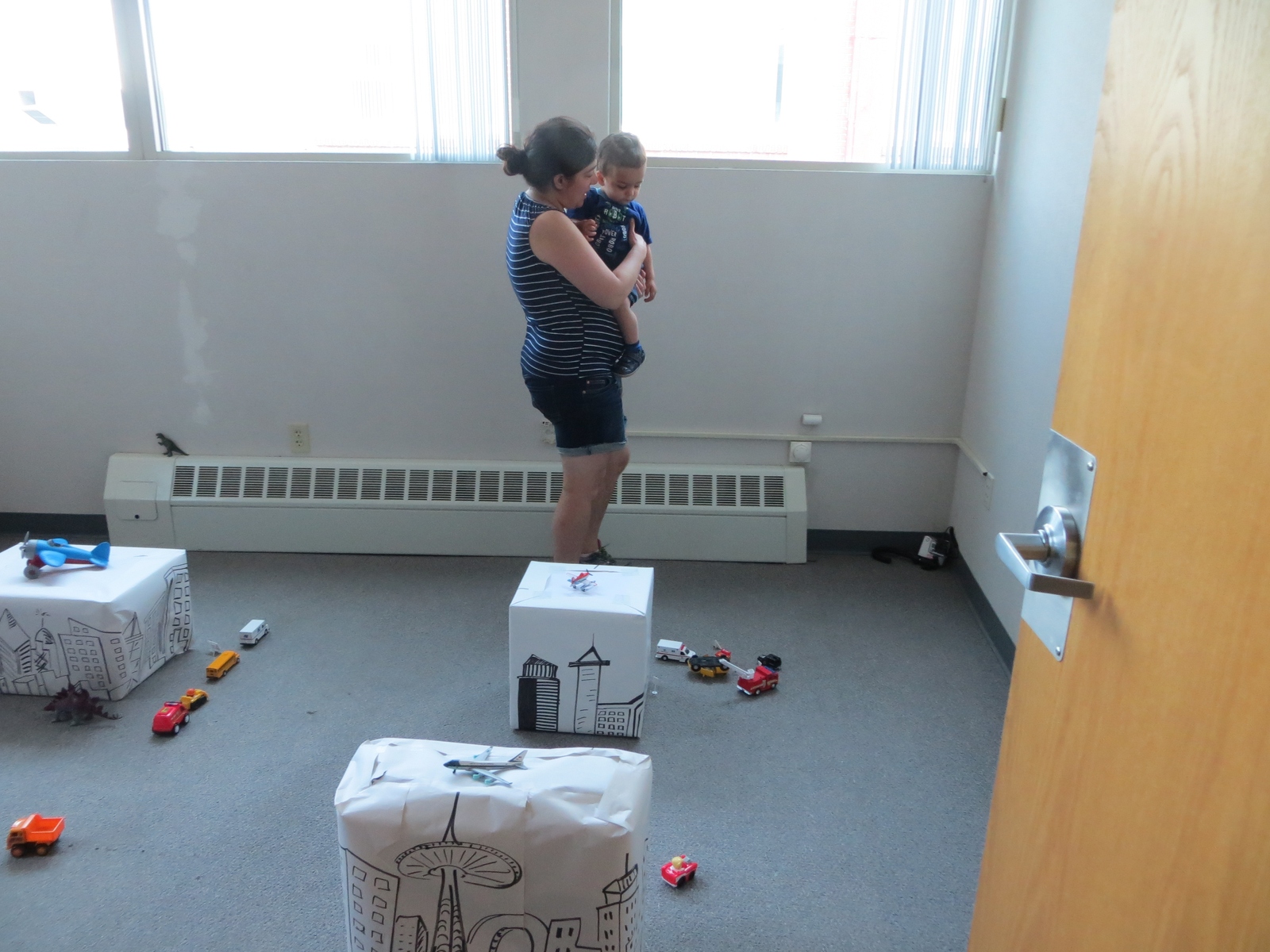
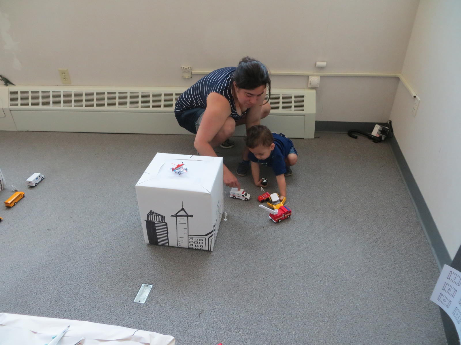
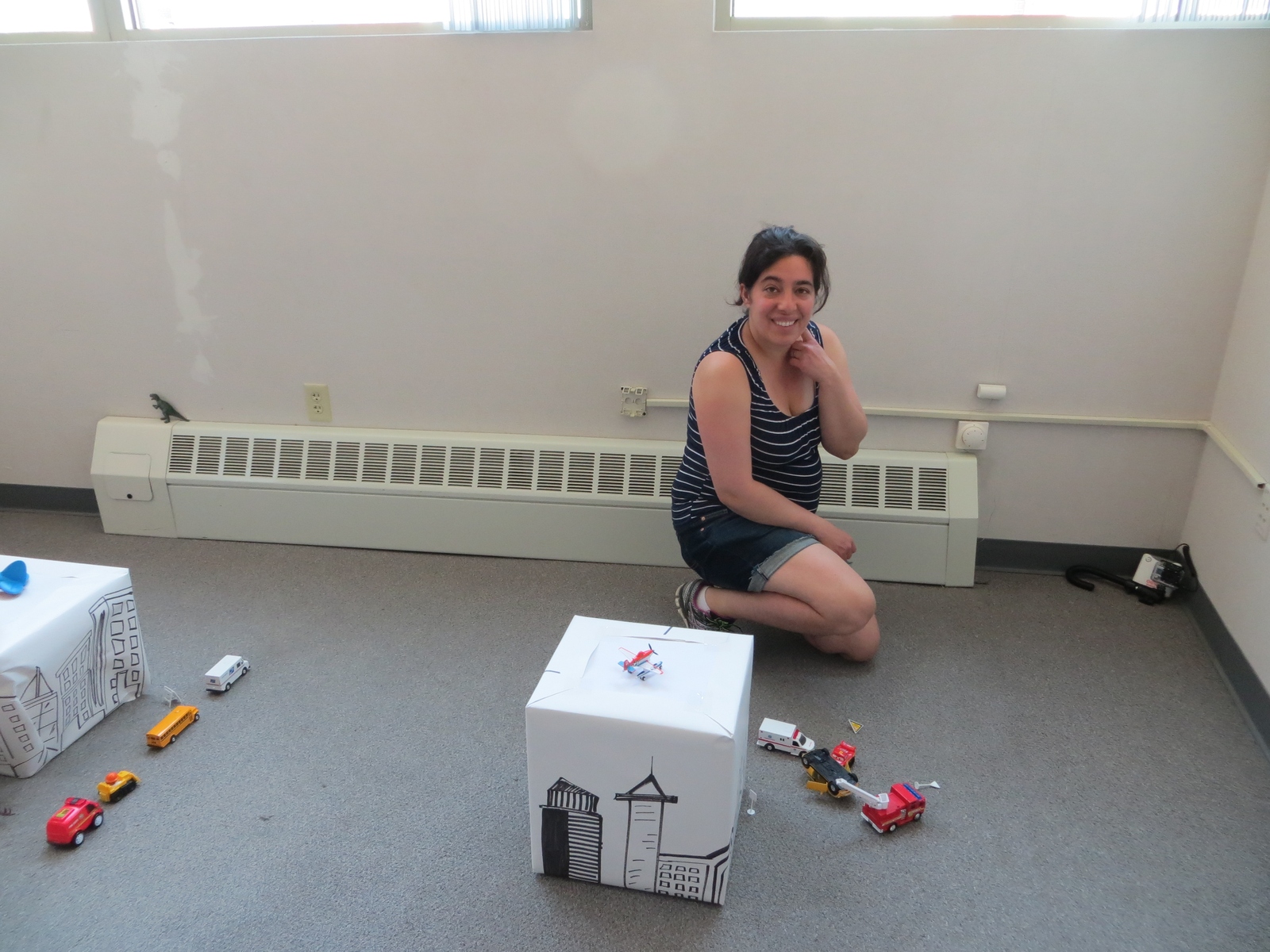
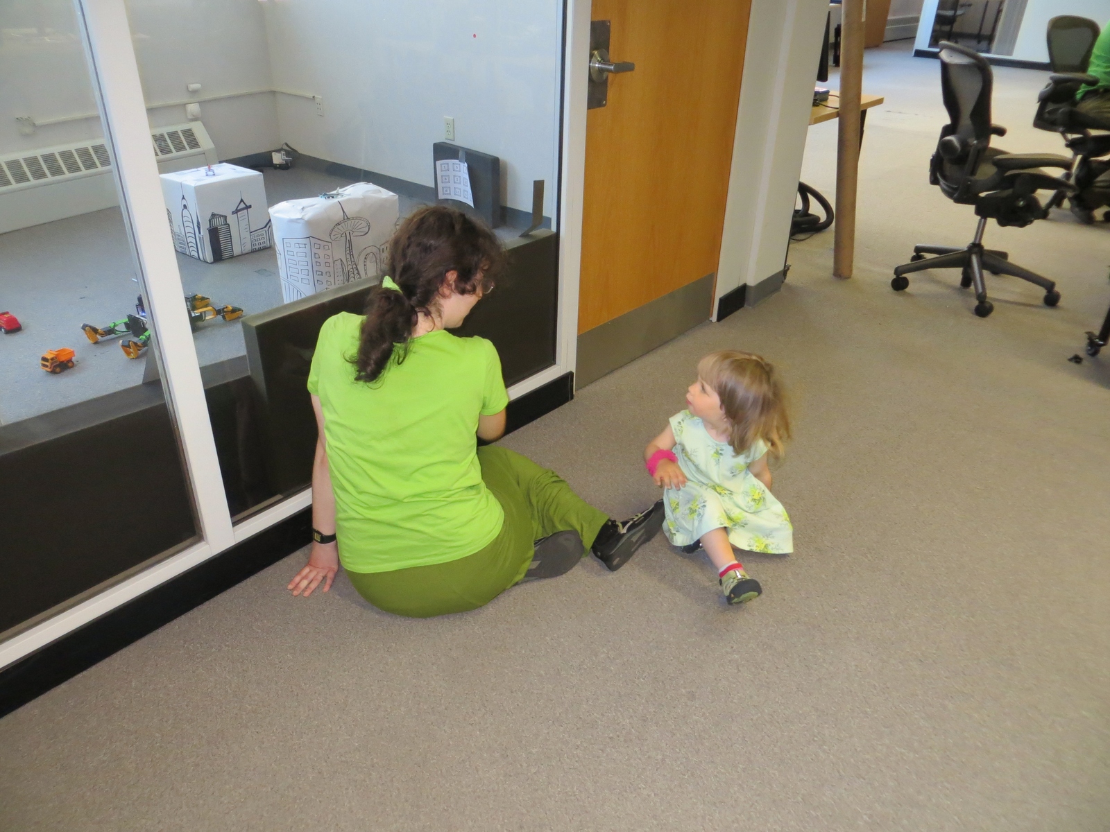
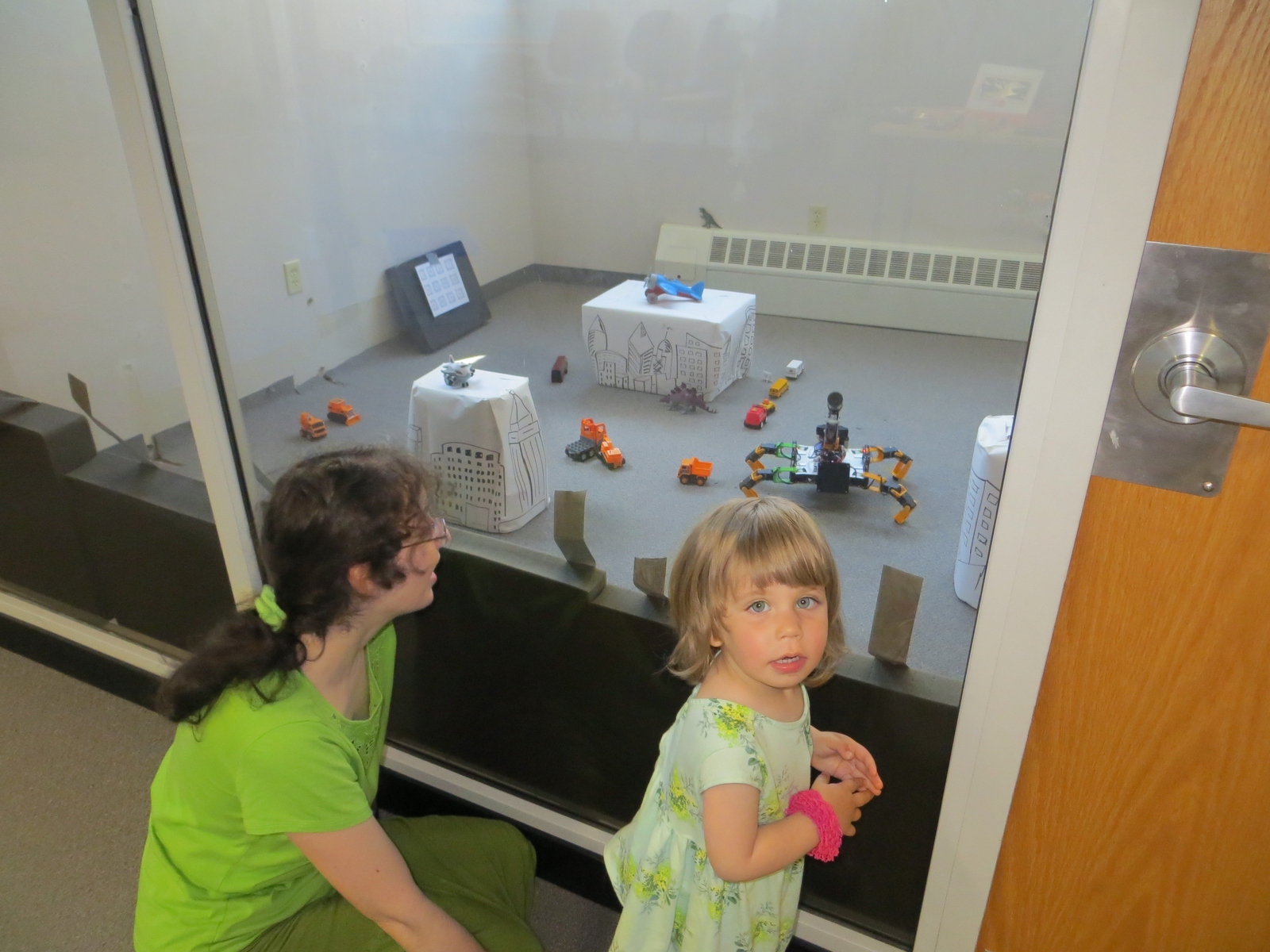
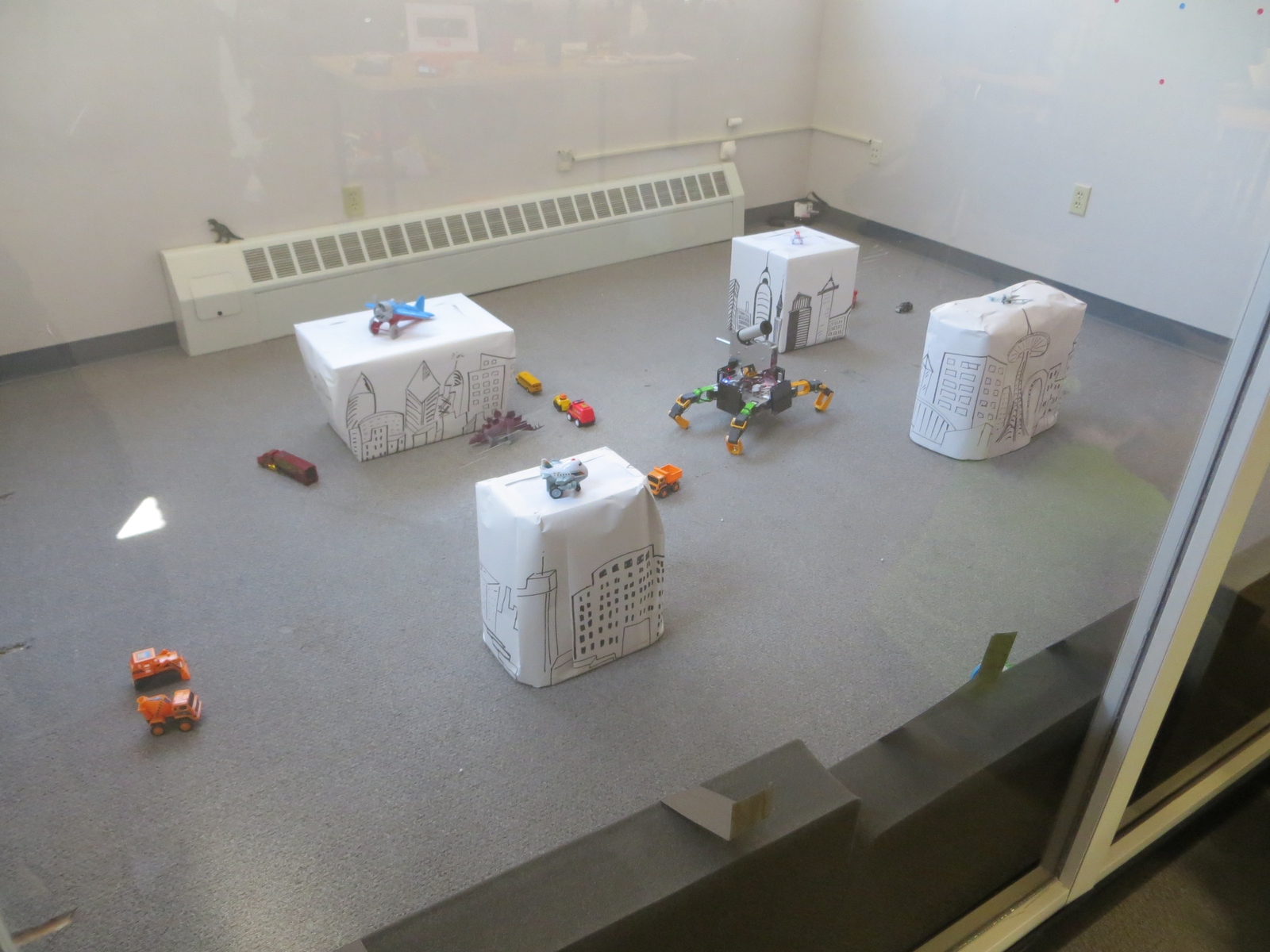
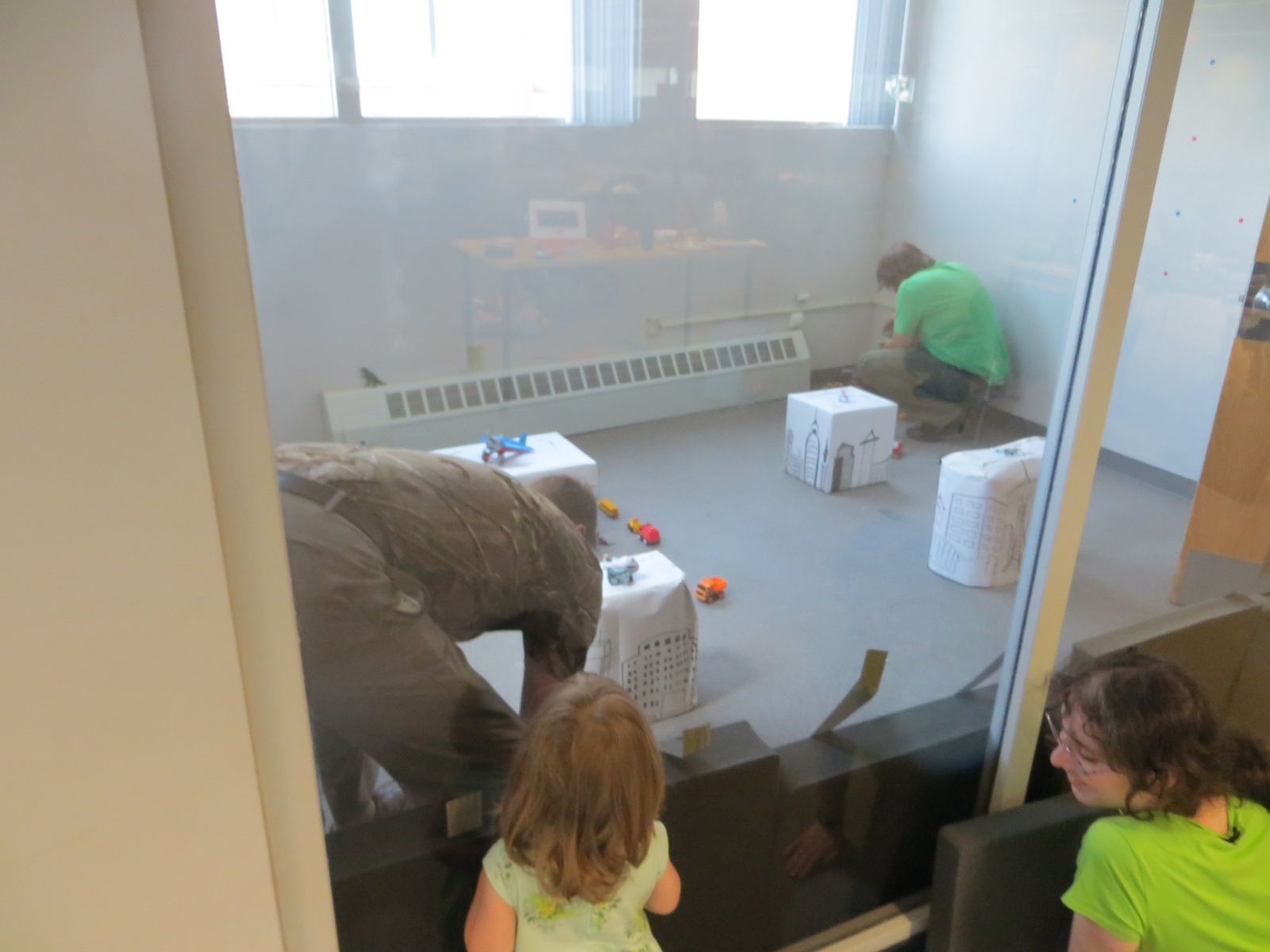
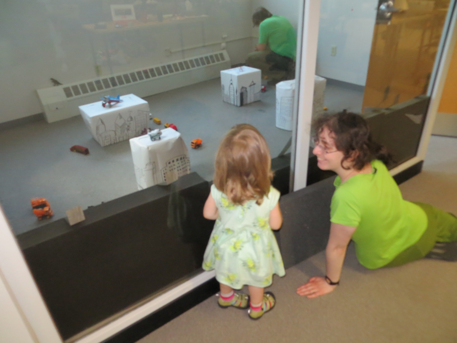
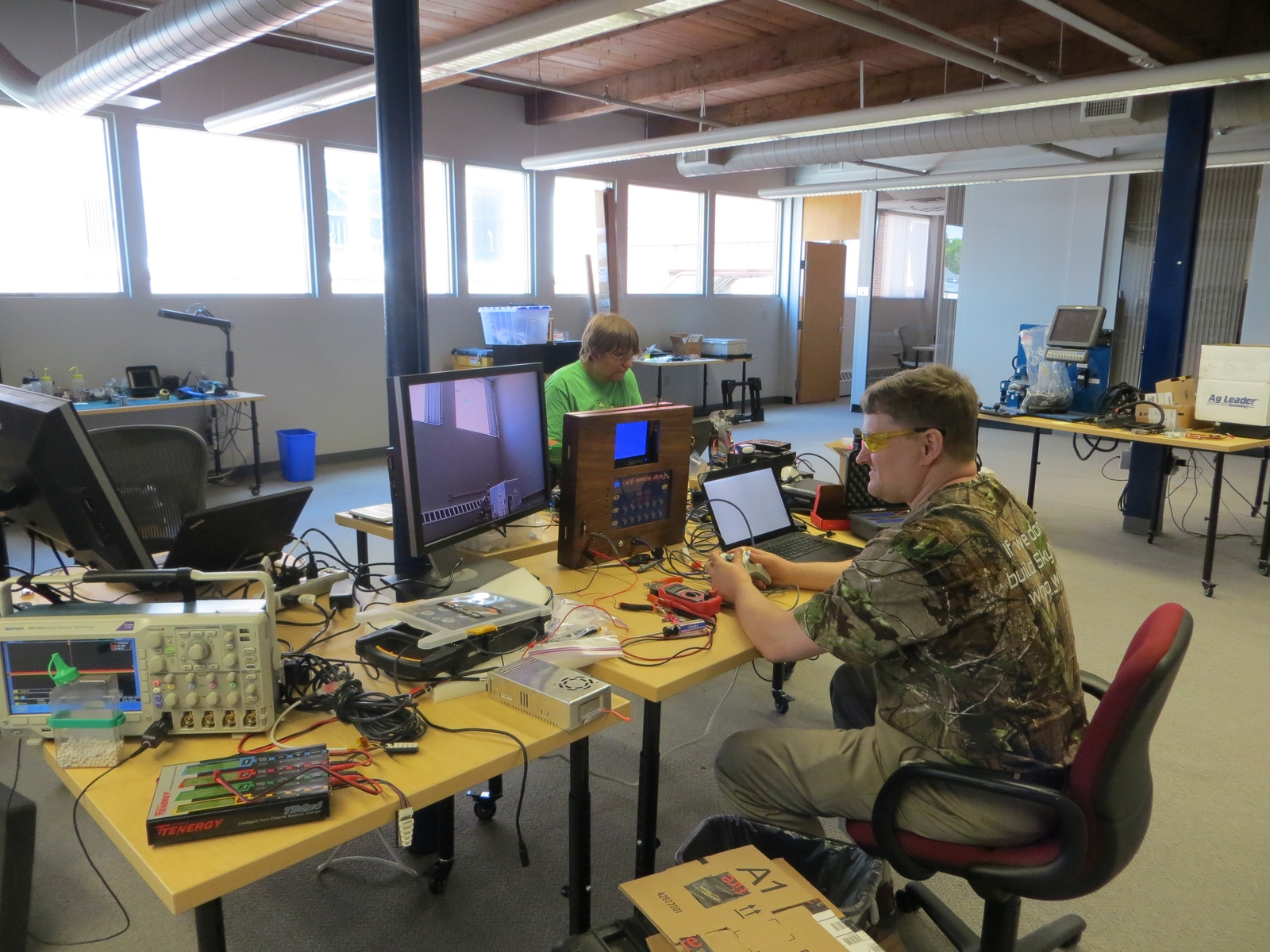
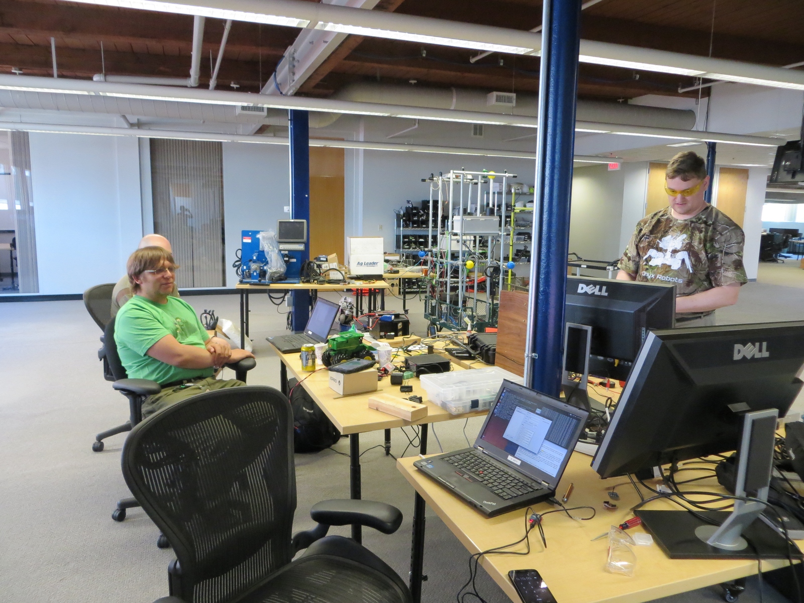
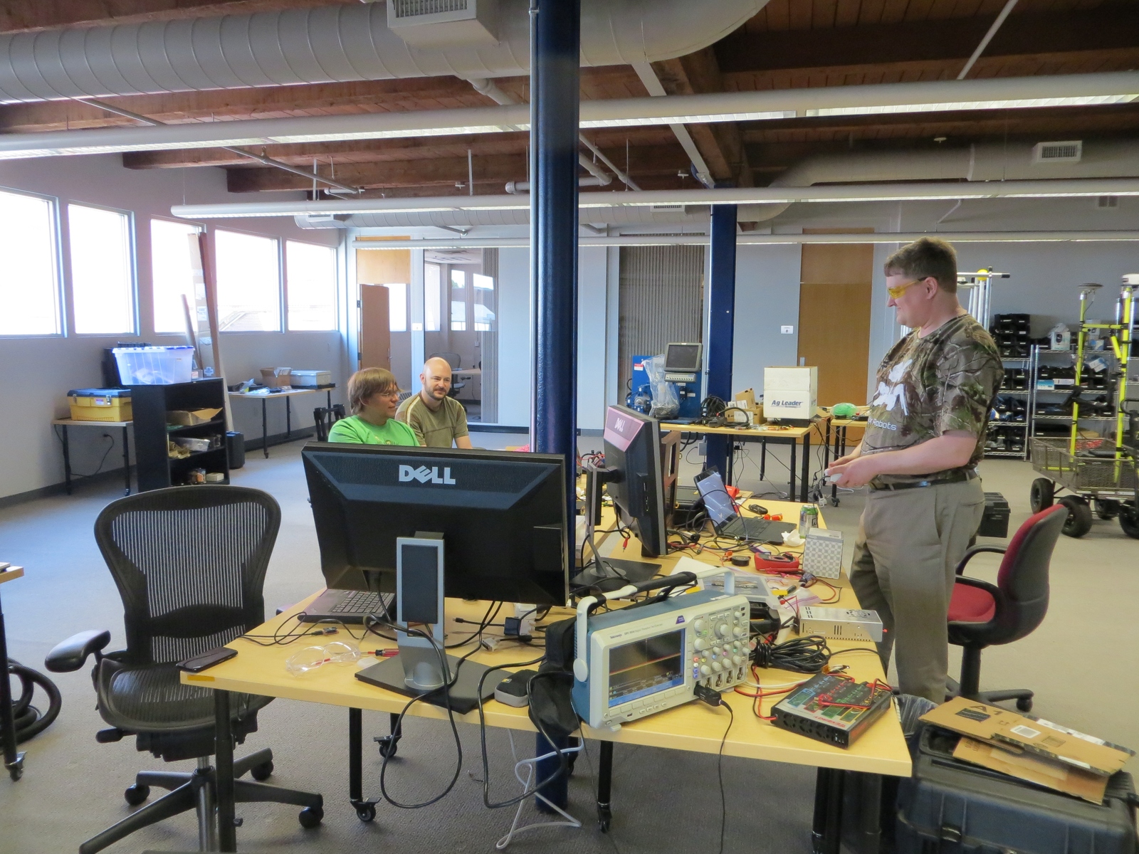
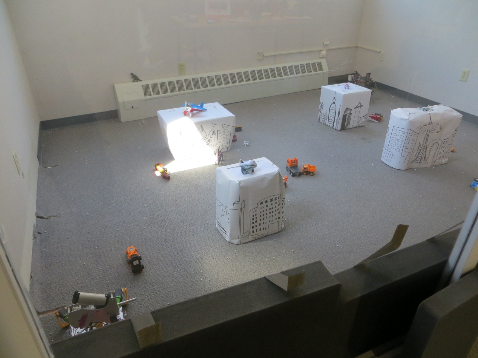
We just concluded the first ever Boston Mech Warfare Expo this weekend, held at Jaybridge Robotics in Cambridge. We had a lot of exciting mech fighting action, learned a lot, and even had a fair amount of exciting repairs! There are many hours of video I need to sort through, but in the meantime, here are some photos:
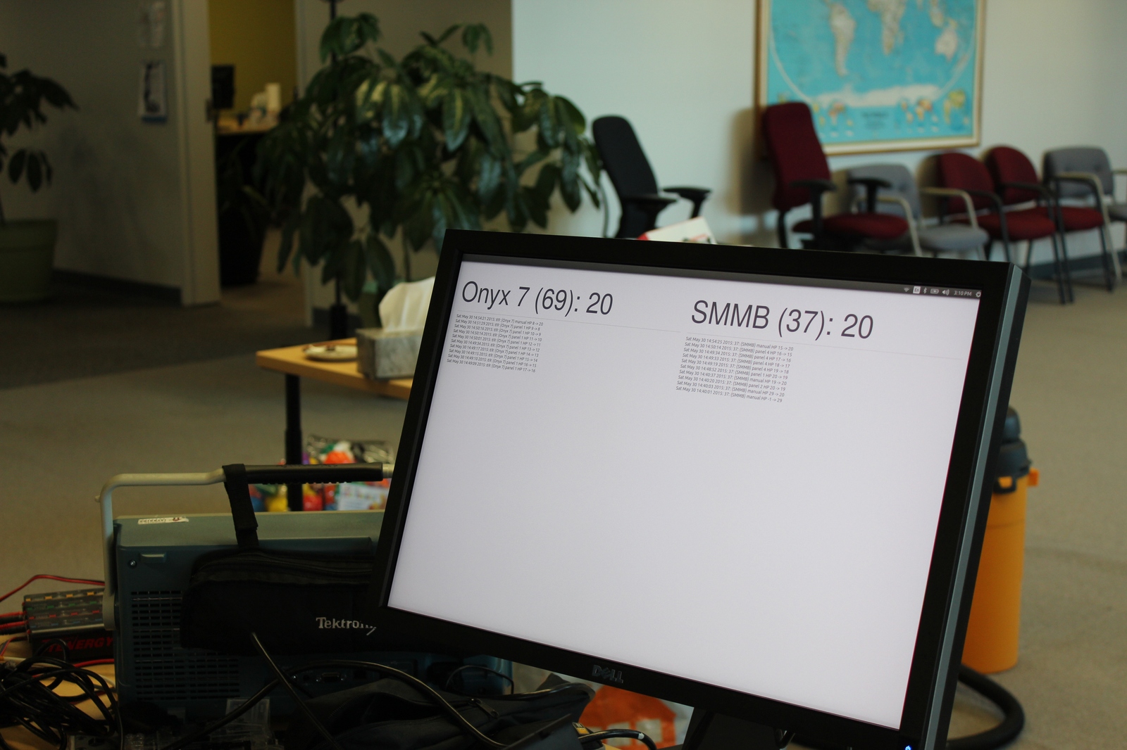
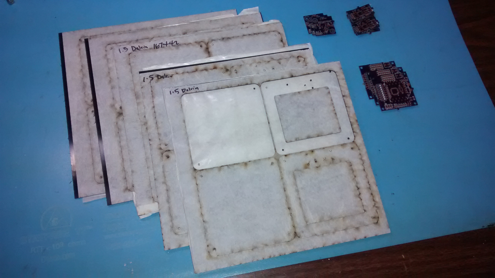
A whole lot of laser cut parts and printed boards just arrived for the scoring system for Super Mega Microbot. We’ll get them put together and tested soon!
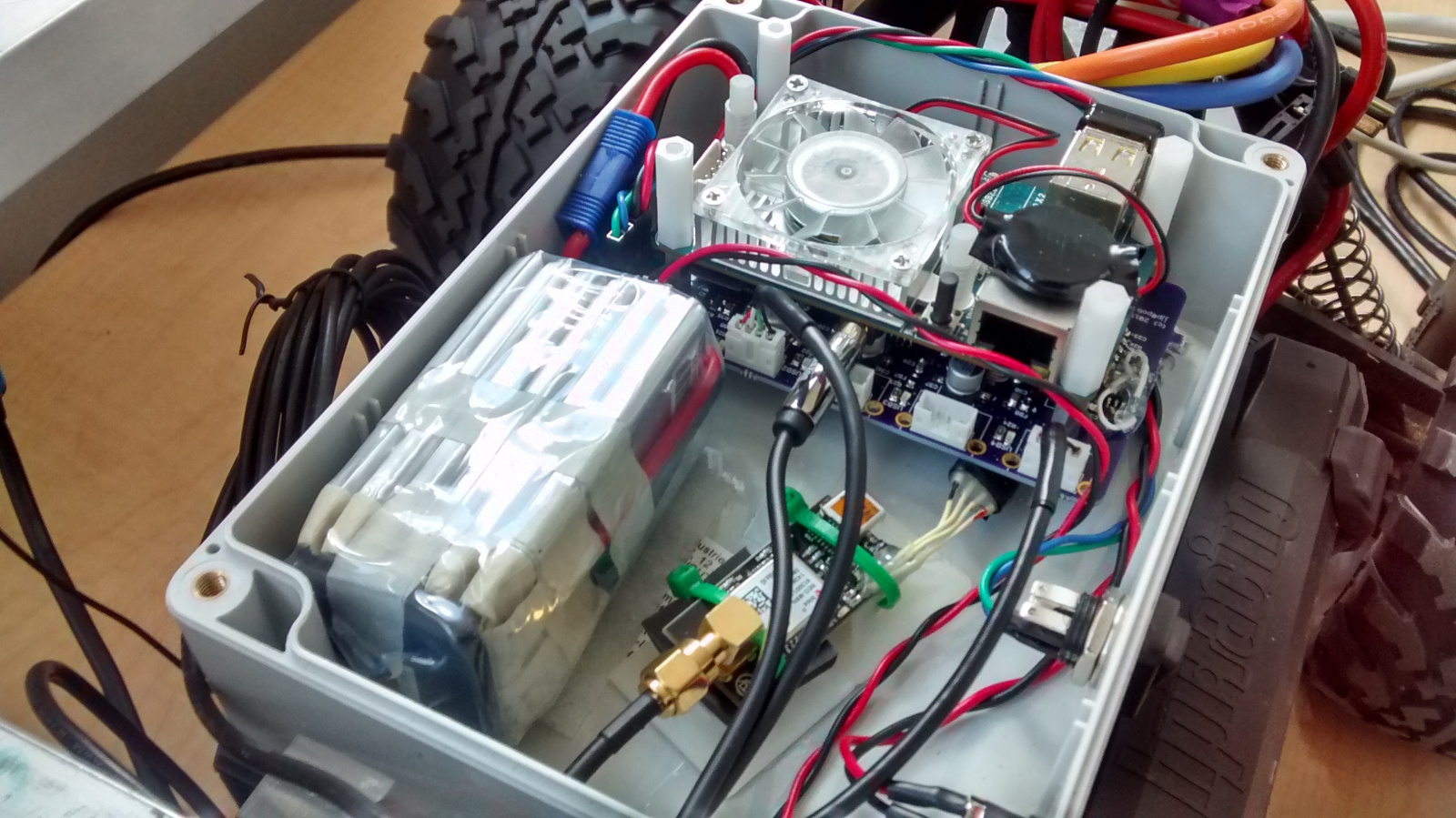
In our efforts to reduce weight and complexity for Savage Solder, over the Christmas holiday and first couple of months of 2015 we designed a new computer system based on the Odroid U3 instead of the Mini-ITX form factor PC we had used previously.
Functions
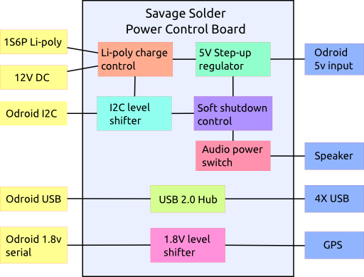
To make that happen, we put together a new power control board which was designed as a “shield” for the Odroid. It has the following functions:
Li-polymer charge management: Previously, Savage Solder used a laptop battery extender, which was functional, but suitable capacities came only in large form factors. We gained a lot of flexibility by using a custom form factor li-poly battery pack, but this means that charge control and safety need to be addressed.
DC/DC step up regulator: The Odroid (and other things), need 5V, so we have a step up regulator to bring the li-poly voltage up to what the Odroid can use.
USB hub: The Odroid has 3 USB ports, (4 if you count the OTG port). We need more than that, and there aren’t many small form factor hubs which would fit into a tiny enclosure. This needed to be USB 2.0 high speed, to support webcams.
Serial level shifter: To reduce the demand for USB ports, we pull out the exposed 1.8V serial port from the Odroid and level shift it up to 5V on a connector that also has 5V power. For Savage Solder, this is used for the GPS.
Speaker power: The control board has a FET to switch the audio power directly from the li-poly pack.
Soft shutdown management: The Odroid’s filesystem could be compromised if it gets powered off unexpectedly. We have a low power microcontroller which reads a discrete switch, informs the Odroid, and powers the system off after the Odroid has had a chance to shutdown cleanly.
**I2C Level shifter:**The Odroid’s expansion port I2C is level shifted to the li-poly voltage level to communicate with the li-poly charger control IC and the shutdown management microcontroller.
Functional block diagram
Components
These were the primary components that the rest of the board was designed around:
Part
Manufacturer
Function
BQ24192
TI
Li-poly charge management
LTC3124
Linear
5V step-up regulator
CY7C65632
Cypress
USB hub
ATTiny841
Atmel
Soft shutdown control
TCA9517
TI
I2C level shifter
SN74LVC1T45
TI
Serial level shifter
PCB
One of our goals with this design was to be pretty sure that the board itself would not be the cause of power problems, signal integrity problems, or really any sort of problems. Thus each USB port’s power is separately switched with a separate large decoupling capacitor and the USB signals have ESD protection. The board itself is 4 layer to give a proper ground plane under each of the USB traces and keep the impedance matched well. All the external connectors with power are separately decoupled and have PTC resettable fuses inline.
As mentioned, the board was designed as a “shield” for the Odroid. That meant that the mounting holes matched up with Odroid’s, and that the Odroid’s expansion port connects through with a stacking connector. Additionally, the USB connection was made by desoldering the Odroid’s vertical USB connector and using another stacking pin header to connect the two boards.
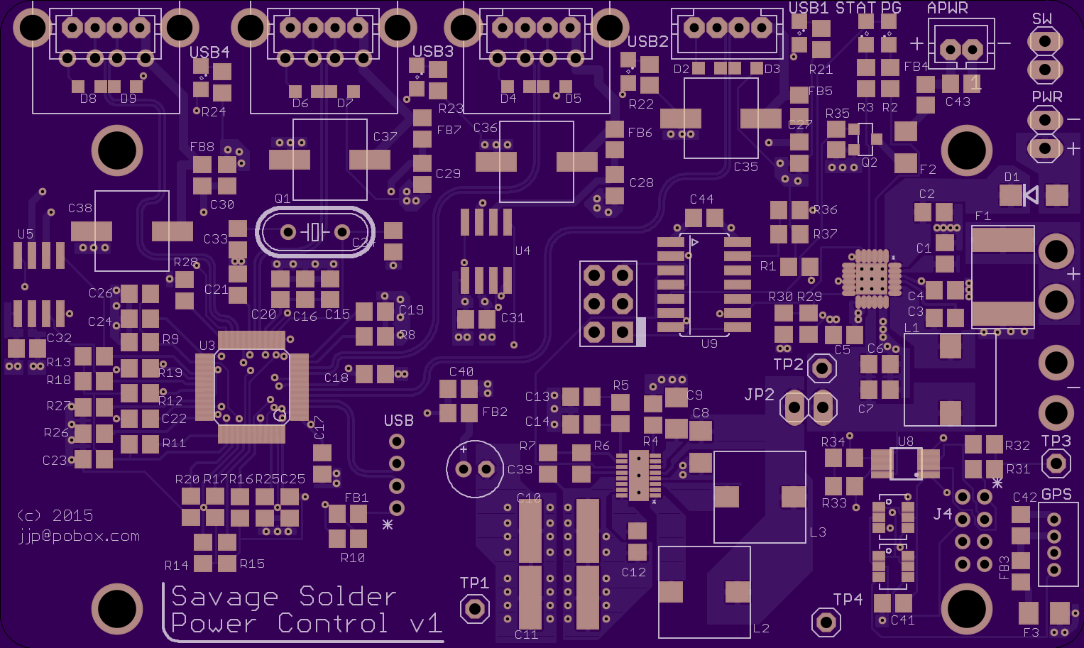
The board was manufactured on OSHpark’s 4 layer process, which worked out just fine for this project.
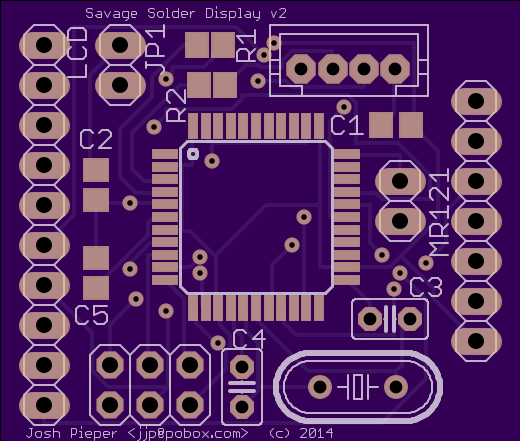
oshpark.com rendering
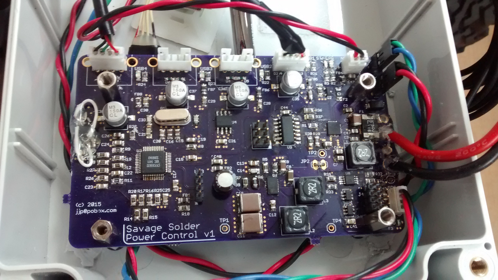
Assembly was challenging, especially for the QFN parts. The one that we built up so far I assembled by hand, using an iron and a hot air rework station with a lot of retries. If we make a subsequent revision, it will need to be with a toaster oven reflow system, or contracted out. Hand assembly time was probably around 16 hours.
While not strictly on the board itself, desoldering the vertical USB connector on the Odroid was very challenging as well. We ruined one Odroid in the process, and the other needed hand rework to replace some components which were lost in the desoldering process.
Final assembled board
There are of course a number of errata in the version one board, but nothing that couldn’t be reworked in place.
Installation and test
So far, we haven’t identified any performance or reliability problems when testing on Savage Solder. The board ran through our spring testing and RoboGames Robogamellan run without being the cause of any known failures.
Savage Solder competed in the Robomagellan event in the newly restored and most impressive Robogames 2015 this past weekend. We had two successful runs out of 3, one with no bonus cones and one which touched the challenging 0.01 bonus cone. Both runs put us on the top of the leaderboard.
Other competitors
Here are links to videos I found or uploaded from other other competitors from last weekend:
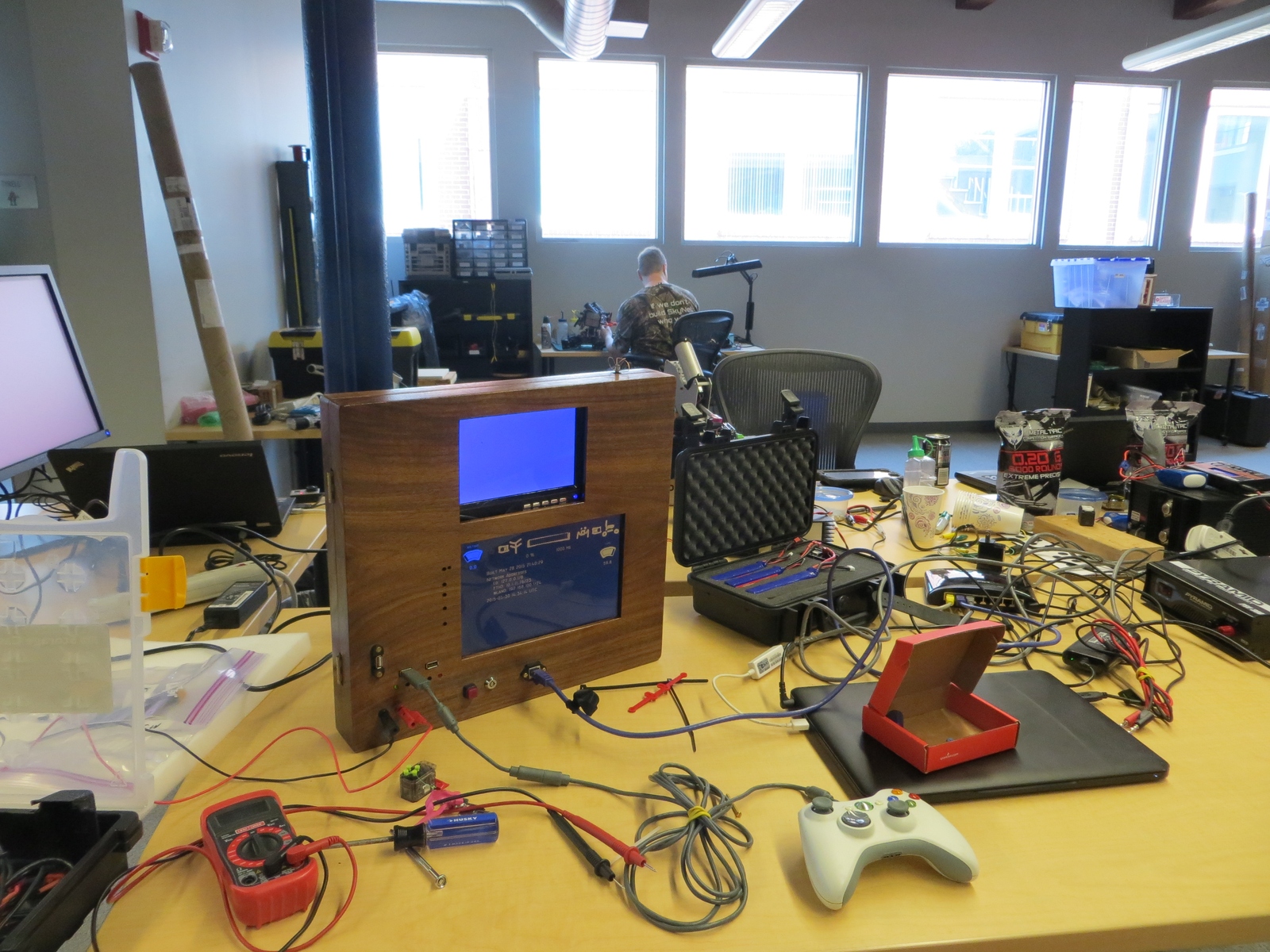
As part of preparing Savage Solder for events this spring, I’ve been overhauling the computer and sensing platform to have higher reliability and lower weight. One of the changes was a new LCD and input interface.
I wrote up the previous LCD here before, which was the width of the car, pretty heavy, and not resistant to the elements. For this version, I wanted to use a smaller screen, and remove the possibility of moisture getting into the case, while still maintaining roughly the same USB interface.
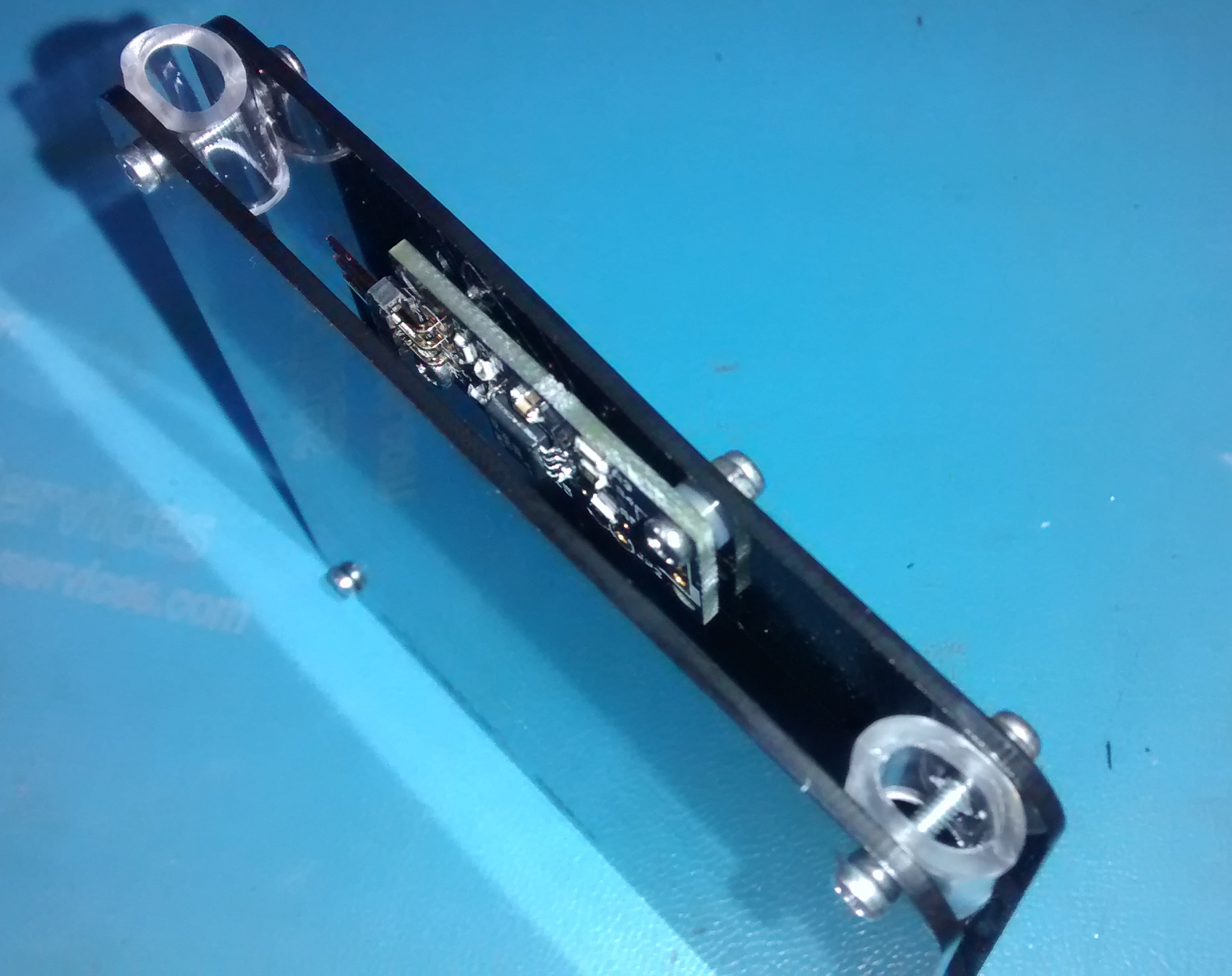
PCB and Assembly
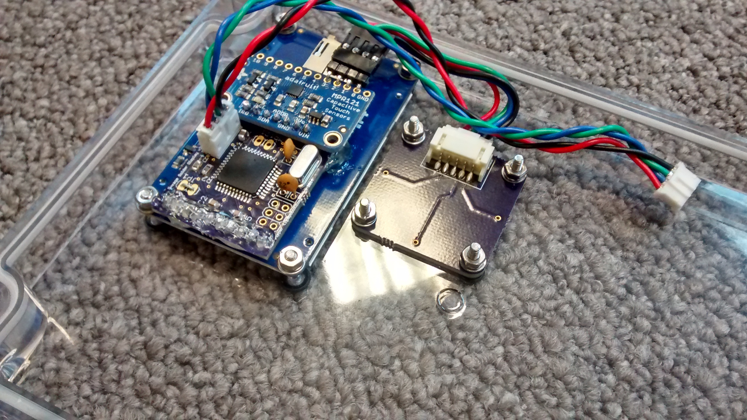
The display I ended up using was the 2.2" TFT LCD from Adafruit. It is color, has sufficient pixels to display everything we wanted, and has a SPI interface. The other half of the solution is the input device, for which I decided to use an off the shelf MPR121 capacitive touch sensor controller, with a breakout board, also from Adafruit.
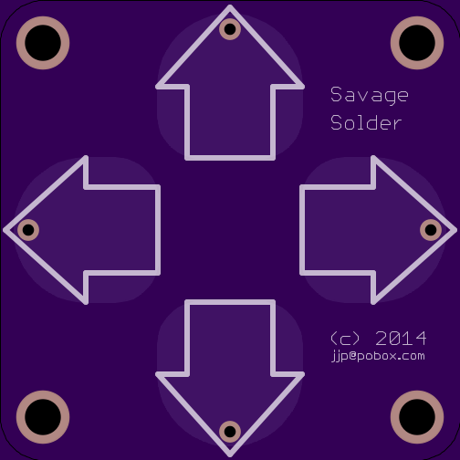
As before, these were glued together with a custom board holding an ATMega32U4 and a few other miscellaneous components. It is mezzanine mounted to the LCD and touch board, and has and external JST connector for USB. Also custom printed was the touch sensor itself. It is nothing more than a PCB with solder-masked copper where each of the touch sensitive areas should be, pulled out to a connector on the back.
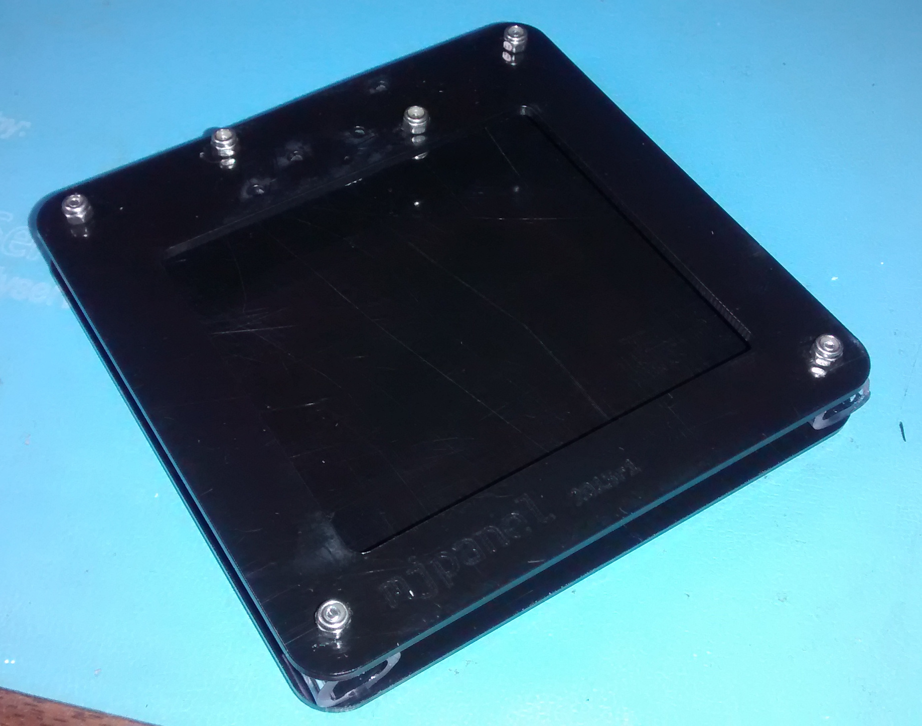
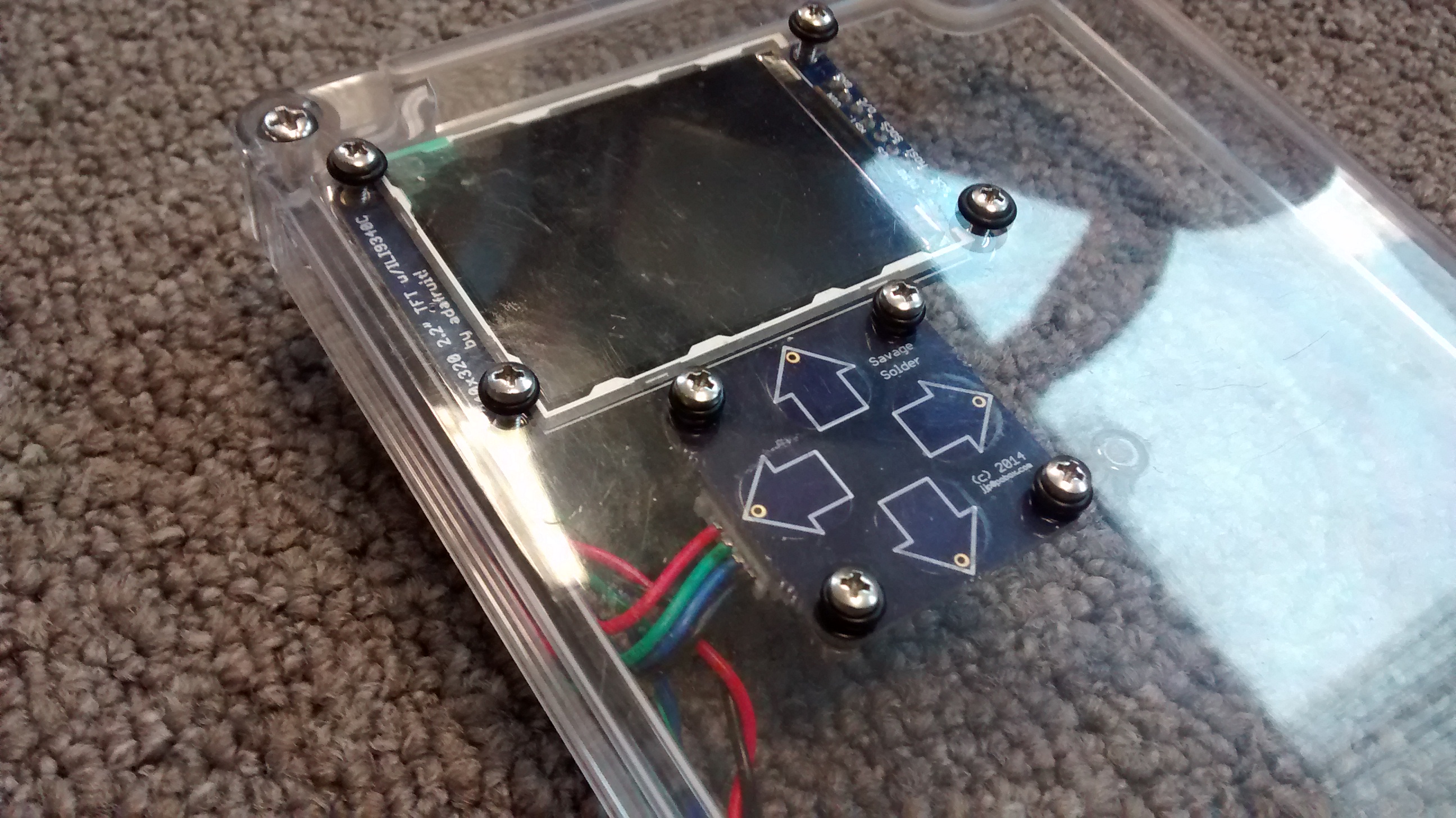
The entire assembly was designed to be mounted to the lid of an off the shelf enclosure with a clear polycarbonate lid (which is where the rest of the electronics is going). The LCD and touch board each have four mounting holes, which are attached with a bolt, nut and lockwasher assembly. Sealing is accomplished with neoprene o-rings on the outer surface of the lid.
Assembled LCD from front
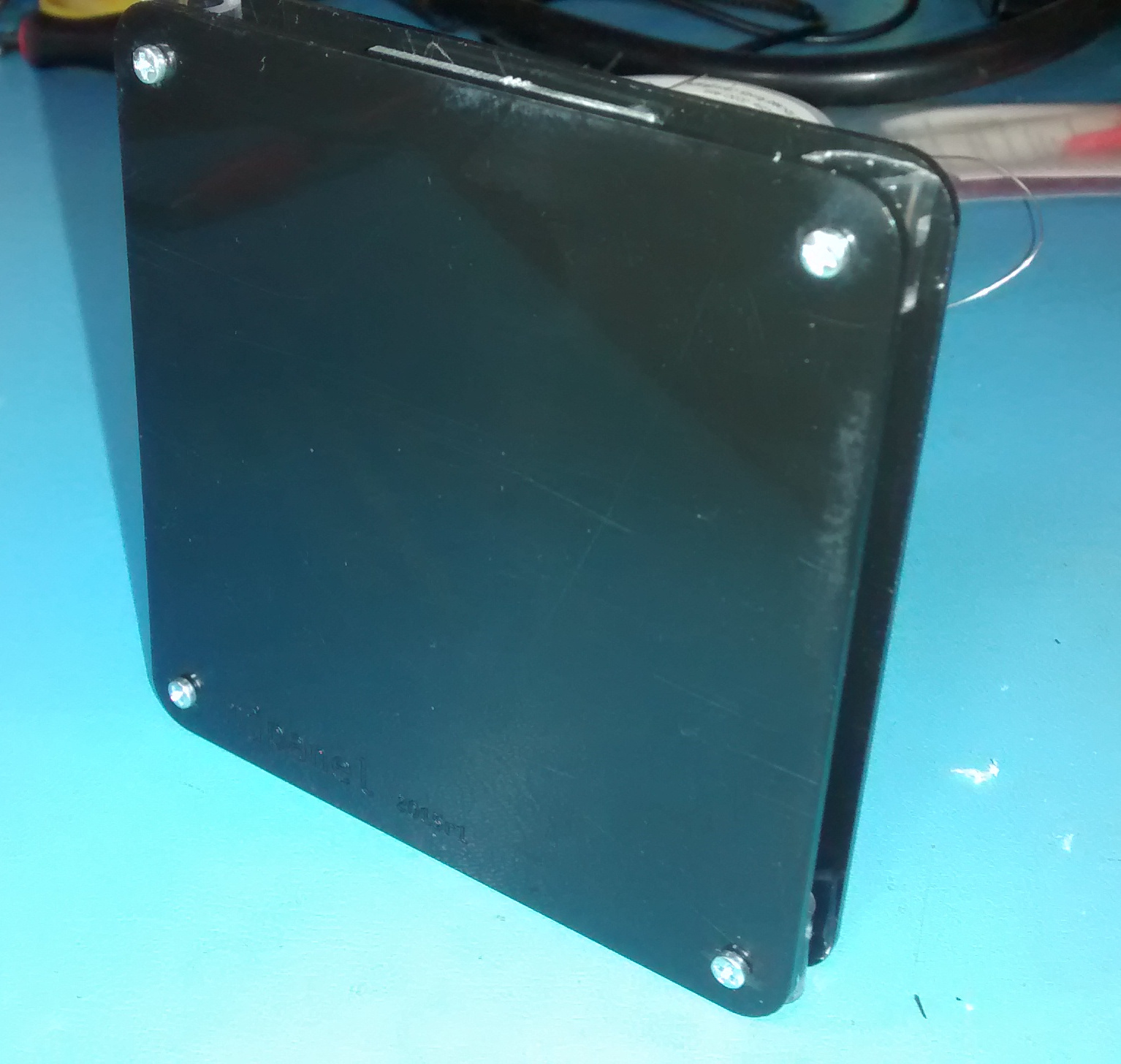
Assembled LCD from back
Software
The MPR121 has a lot of options, many of which influence the performance of the device. The enclosure I am using is an off the shelf one from BUD (PN-1324-C amazon link). It has a polycarbonate lid approximately 1/8" thick, which is kind of at the extreme of what you can get capacitive touch sensors to work through. I was inspired by Adafruit’s MPR121 library, but rewrote it to not require Arduino. I had to tweak a number of the MPR121 constants as well to work under the thick polycarbonate:
MPR121 Register
Adafruit
Savage Solder
CONFIG1
0x10
0x20 (32uA charge current)
Thresholds
12, 6
4, 2
For rendering text on the display, I also based my code on the Adafruit ILI9340 library. Since this LCD controller has to render text one pixel at a time, it was much slower than the HD44780 text-based controller we were using previously. To get remotely acceptable performance, I had to make the AVR keep a framebuffer around, and only re-draw characters which had actually changed.