First Firing Session
To act as a forcing function in our development of Super Mega Microbot, we put together a Mech Warfare style qualification video, showing it driving around for more than 5 minutes shooting at some targets. Here it is!
To act as a forcing function in our development of Super Mega Microbot, we put together a Mech Warfare style qualification video, showing it driving around for more than 5 minutes shooting at some targets. Here it is!
legtool is the library and graphical application I’ve developed for inverse kinematics and gait generation to use with Super Mega Microbot. I’ve pushed a public version of it to github, in the hopes that it may be useful for other developers of legged robots.
I’ve also put together a short demonstration video, showing how to download, install, and use legtool with a gazebo simulated quadruped.
In lieu of actual documentation (or possibly to start generating the text of some), I’ve written some text describing what legtool does and how to to use it below.
legtool is a python library and PySide based graphical application useful for pose generation, inverse kinematics, and gait generation for legged robots. It consists of a set of python libraries, and a graphical debugging application which uses those libraries to allow a developer to explore legged locomotion. It has primarily been tested on Ubuntu linux, but may be portable to other operating systems.
legtool is not yet packaged for installation, so all you need to do is clone the github repository and install the dependencies as documented in the README.
git clone https://github.com/jpieper/legtool.git
Legtool by default creates a configuration file in ~/.config, however, you can specify an alternate configuration on the command line using the -c option. If you have multiple robots, or a simulation and an actual robot, you will want to keep multiple configurations around.
The first tab which is active, the “servo” tab, contains controls to select the servos to control and configure them, along with controls to maintain a list of named poses, where each pose consists of a set of servo positions.
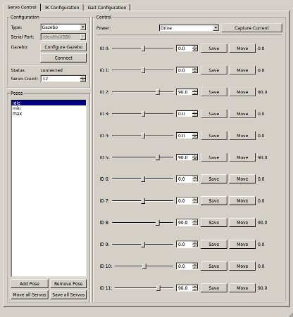
legtool servo tab
Here you can move servos individually to verify their operation, and compose poses. The only use for poses currently is in the later inverse kinematics tabs, so there is no need to define more than idle, minimum, and maximum.
The second tab, the IK tab, lets you configure which servos are in which leg, what sign they have, and also the geometry of the legs. The lower right corner visualizes the achievable region of operation in 2D. You can select alternate projections, and change the centerpoint of the test using the IK Offset group. Clicking on the rendering will command that leg to that position.
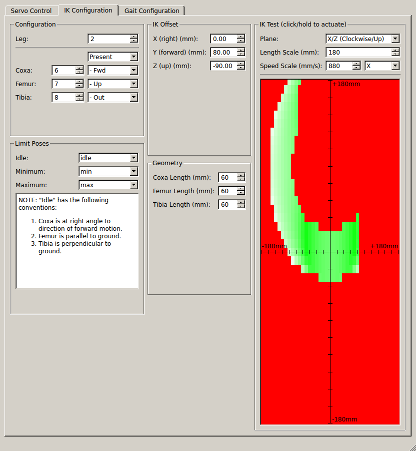
legtool IK tab
The third, and currently final tab, contains controls to allow configuring the placement of all shoulder joints, marking the center of gravity, and configuring the gait engine. It provides several debugging facilities to allow visualizing the results of the gait engine.
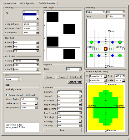
legtool gait tab
The geometry configuration is in the upper left. The shoulder position can be set individually for each leg. The center of gravity and idle position are common to all legs. The gait configuration area in the lower left selects which gait to use, and then exposes a number of configuration options for that gait.
The remainder of the tab is devoted to interactive tools for debugging the gaits:
Yesterday I pushed the release of the newest version of pygazebo to github, 3.0.0-2014.1. This version has two big changes, the first is that I’ve updated all the message bindings for gazebo 3.0.0, which gets two new messages, CameraCmd and SphericalCoordinates. The second, and larger change, is a switch from eventlet to trollius for asynchronous coroutine operation.
trollius is an implementation of the python3 asyncio/tulip library for python2. It is largely API compatible, with the biggest exception being that as a library, trollius can’t support the new python3 “yield from” syntax. pygazebo internally uses an API compatible subset.
The biggest reasons to switch were:
The new release is on github and pypi, so a newer pygazebo is only a “pip install pygazebo” away.
AVC 2014 has come and gone! Savage Solder placed 2nd in the doping class this year, with two of three successful runs. The first run ended after about 5 feet when the replacement ESC seemed to overheat after being left on for too long before the starting line. The second run was flawless, hitting the hoop and the ramp. The third run was nearly perfect, only missing the hoop.
Congrats to all the other teams, there were a lot of successful and inventive entries this year!
I’ve found two good videos of the third run so far, the first from the official livestream at time 12:00
https://www.youtube.com/watch?time_continue=720&v=l2fHt7VxhlE
And the second from hearthdragon:
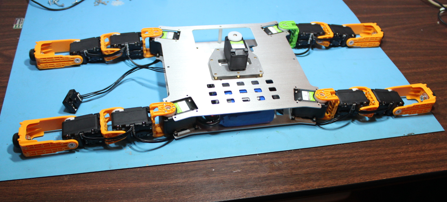
This video shows some gaits for our Mech Warfare entrant, tentatively named “Super Mega Microbot”. First there is a slow statically stable gait, then a faster two leg at a time gait.
Technically, it has been walking for a couple of weeks, but this is the first time with the actual aluminum machined chassis plates, so that it makes for a nice video. All the previous testing has been done with some polycarbonate plates that I cut out by hand. We haven’t mounted the onboard computer or turret yet, but that is coming soon. In their place is an extra lipo battery to make the center of gravity more reasonable. This gait was driven by a PC over the serial cable seen in the frame.
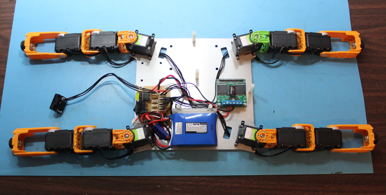
A few pictures from the in-progress mech build…
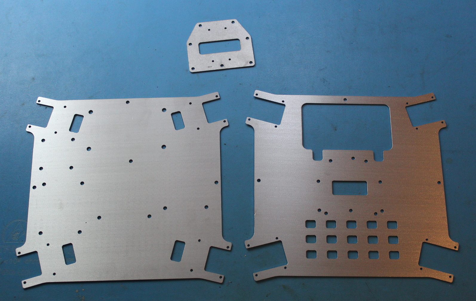
Aluminum chassis plates
Lower chassis with some boards populated
Mockup assembly of chassis minus turret and computer
One of the improvements we made for this year’s Savage Solder entry into the Sparkfun AVC (and maybe other competitions, I’m looking at you Vecna Robot Race), is an updated baseboard. Our old baseboard was a Teensy 2.0+ soldered onto a hand-built protoboard and then wired up to an external IMU mounted on the front of the chassis. For fun, I decided to replace that board with a more integrated unit which installs more cleanly into the car chassis and is based on the firmware I’m developing for the ARR.
The board hardware includes:
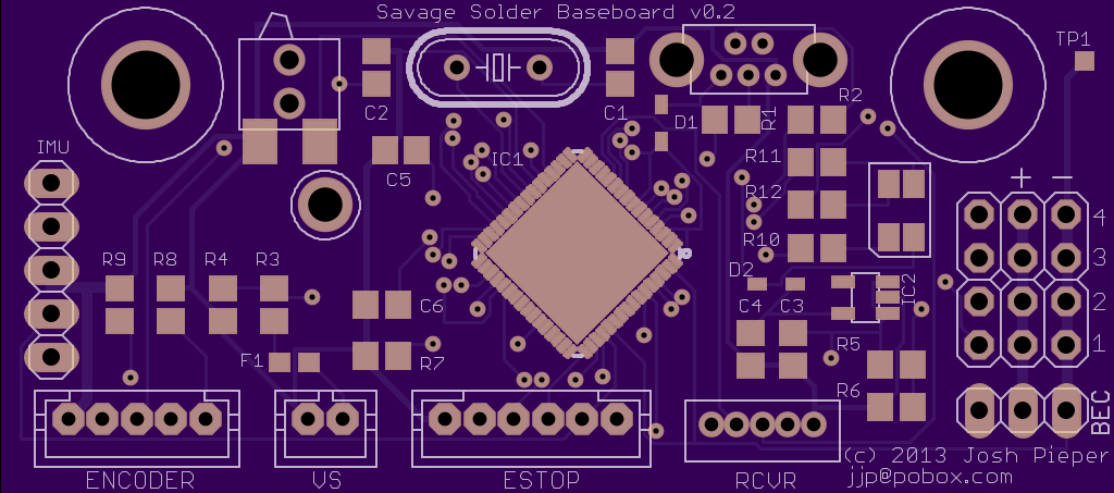
oshpark.com rendering
This was another oshpark.com job, and the layout was relatively straightforward. The biggest wrinkle was that the first revision was non-functional due to a broken AVR eagle package. Who would figure that the no-name library I downloaded from some shady site didn’t have a ground pad? The crazier thing was that it kind of worked, despite all the vias that it placed under the part were shorted out by the pad.
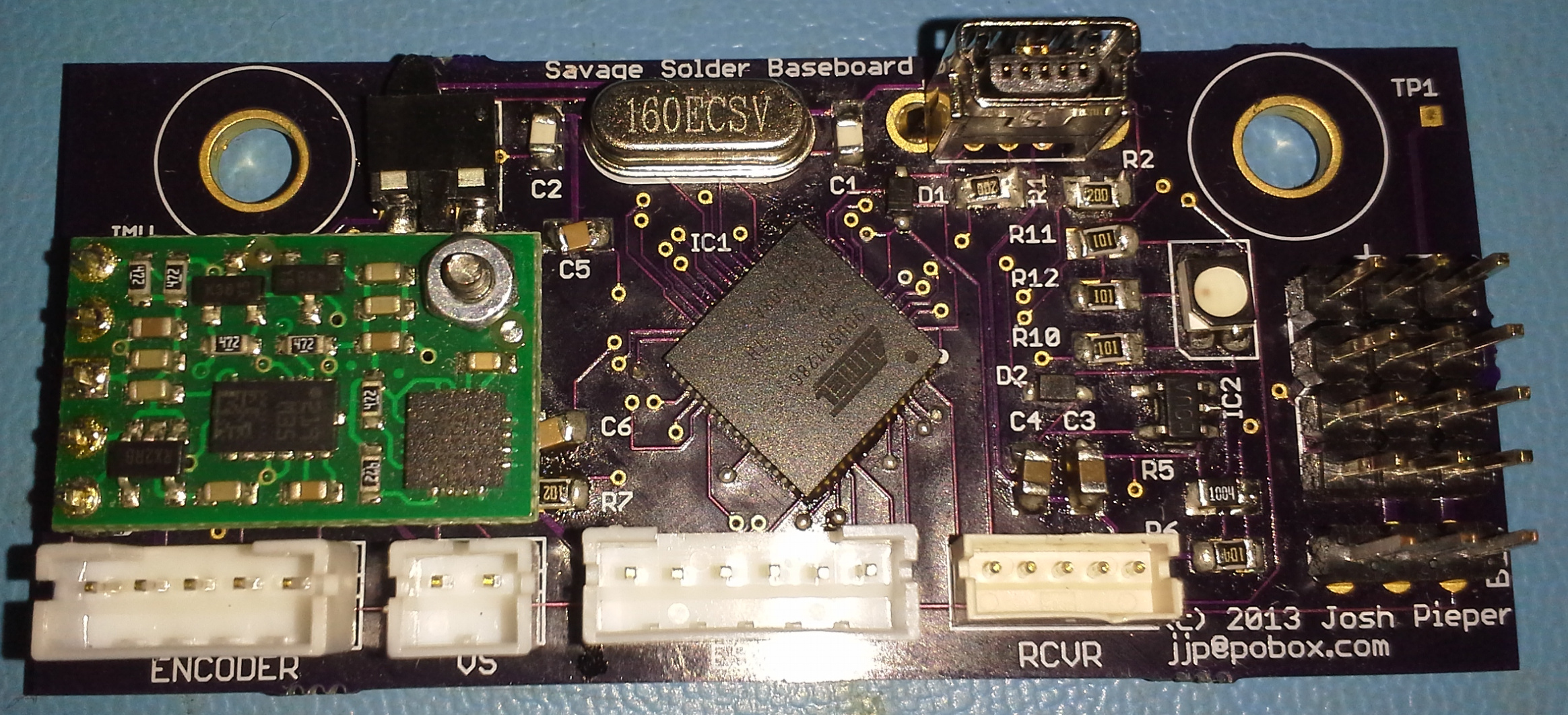
Baseboard fully populated
The board was mechanically designed to fit into an otherwise unused space forward of the steering servos on our Savage Flux chassis. There are two screws there that attach the chassis to some suspension components on the underside. I just replaced those two screws with slightly longer ones, and added a spacer underneath.
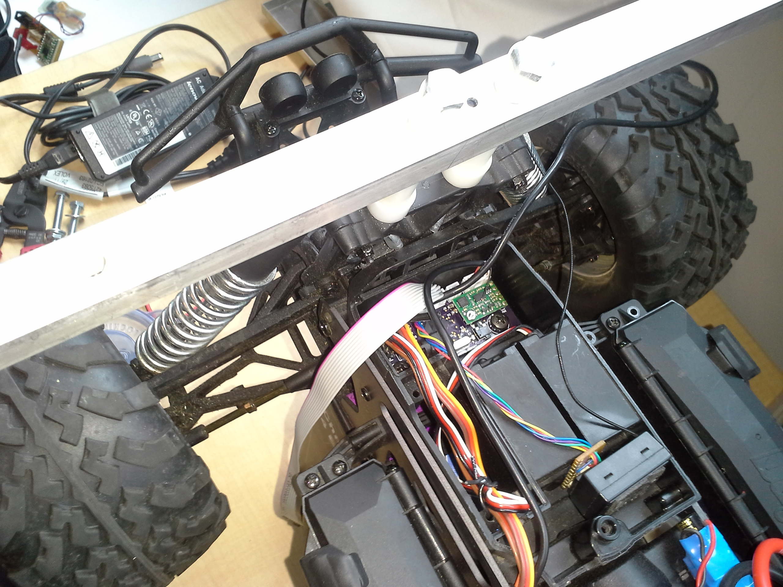
Baseboard installed in Savage Solder
As I mentioned before, the firmware was based on that I am creating for the ARR. The basic architecture is the same, in that a master computer communicates with the baseboard over USB, and the baseboard provides high rate servo, I2C communication, and other miscellaneous functionality. I’ve written up the basic servo functionality and engineering test fixture of the firmware previously. Versus our previous controller, the servo control is much improved, both in the precision and accuracy of input and output, as well as having access to more channels. While the firmware supports 8 input and 8 output channels, the Savage Solder baseboard only has 3 inputs and 4 outputs routed to any connectors.
I added a few new pieces of functionality to make the firmware usable for Savage solder, namely:
The baseboard has been installed in the car since late July 2013. Yes, this post is very belated! In that time, it has been used for all of our testing and appears to be working quite well. Or rather, it hasn’t been the source of any problems yet!
We’ve been hard at work on a Mech Warfare contender. Recently we got to a feature complete point on our turret design and build, and I put together a short video demonstrating its features. Enjoy!
In Part 1 and Part 2, I described why we’re trying to measure localization accuracy, and the properties of a GPS receiver that allows us to do so. In this post, I’ll describe the technique we used to measure accuracy of our solution purely from recorded data, without needing to go back out to the field every time a change was made.
The technique we used to measure localization accuracy is somewhat similar to the Allan Variance plots used in part 2. Here, we take a large corpus of pre-recorded sensor data from the vehicle and re-run it through the localization solution. The trick is that for a given time window, the GPS updates are witheld from the filter, then at the end of the window, the difference between the estimated position and the measured GPS position is recorded. The cycle then starts anew at the current time, with the estimate being reset to the best possible one, and GPS denied until the next window end. Each sampled error is one data point showing how far off the localization solution can be after that much time with no GPS.
We expect this to be effective because, as the plots in part 2 showed, over short time windows, the average drift in the GPS is actually pretty small. For instance, the u-blox 6 on savage solder, within a 5s time window, will have drifted only about 0.6m with 95% confidence.
Once the results have been collated for a given time window, say 1s, we repeat the entire process for 2s, then 3s, etc. The curves this produces show how rapidly the position error in localization grows with time. The lower the value is at longer time intervals, that means the vehicle is more robust to GPS outages or drifts.
A plot of our 2013 AVC localization solution’s accuracy is shown below. It was measured over about 30 minutes of autonomous driving, mostly recorded in the weeks leading up to the 2013 AVC. I have superimposed on it the 68% and 95% confidence in the u-blox drift for reference. If the localization solution were perfect, we would expect the measured errors to approximately line up with the GPS drift over the same time interval.
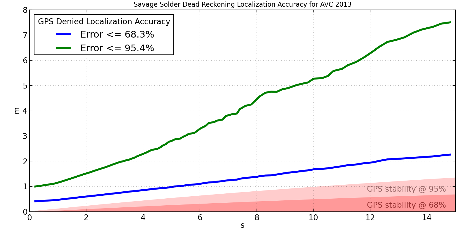
Savage Solder AVC 2013 Localization Accuracy
This shows that the accuracy isn’t terrible, but isn’t particularly great either. After 15 seconds, it is off by less than 2m two thirds of the time. However, in order to capture the best 95% of results, we have to look all the way out to 7.5m, which clearly isn’t too usable. For a course like the Sparkfun AVC one, you can roughly say that errors larger than 2 or 3 meters will result in a collision with something. This implies that Savage Solder can run for about 3 to 5 seconds with no GPS and be not terrible.
We have a couple of theories for where the largest sources of error are in the system as shown in the above plot:
Looking back at part 1, this technique measures up pretty well. It:
You can tweak the localization algorithms in software as many times as necessary, each time accurately assessing the results, and never once need to go out and actually drive the robot around.
I managed to clean up the python bindings to Gazebo I wrote when testing mech gaits in simulation, and have released them publicly as pygazebo.
All you have to do is:
pip install pygazebo
From the README, a simple example:
import eventlet
from pygazebo import Manager

manager = Manager()
publisher = manager.advertise('/gazebo/default/model/joint_cmd',
                              'gazebo.msgs.JointCmd')

message = pygazebo.msg.joint_cmd_pb2.JointCmd()
message.axis = 0
message.force = 1.0

while True:
    publisher.publish(message)
    eventlet.sleep(1.0)
and you’re off and ready to code!