Updated baseboard for Savage Solder
One of the improvements we made for this year’s Savage Solder entry into the Sparkfun AVC (and maybe other competitions, I’m looking at you Vecna Robot Race), is an updated baseboard. Our old baseboard was a Teensy 2.0+ soldered onto a hand-built protoboard and then wired up to an external IMU mounted on the front of the chassis. For fun, I decided to replace that board with a more integrated unit which installs more cleanly into the car chassis and is based on the firmware I’m developing for the ARR.
Hardware
The board hardware includes:
- 3 servo inputs: The Savage Flux RX receiver has 3 outputs, for throttle, brake, and an auxiliary channel.
- 4 servo outputs: We are only using 2 channels currently, but it was trivial to wire up 2 more.
- Pins and mounting for stacked MiniIMUv2: Rather than have the IMU need a long-run cable and dedicated mounting, it is now integrated into the baseboard. The I2C can be run at a 400kHz in this configuration, and thus the IMU can be sampled at a higher rate if necessary.
- USB device port for connection to host PC: We use a small form factor Intel motherboard as a host computer, the USB connection, while not particularly reliable, is sufficient for the competitions Savage Solder enters.
- Sensored motor feedback for odometry: This provides the primary odometry for the car.
- General purpose digital inputs for emergency switch, and bumper switches: Our emergency override switch and robomagellan bump switches can all be treated as simple logic inputs.
- Battery voltage sense: One ADC channel was wired to a connector to measure the drive battery voltage.
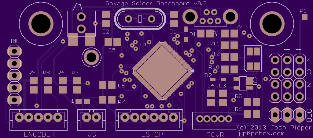
oshpark.com rendering
This was another oshpark.com job, and the layout was relatively straightforward. The biggest wrinkle was that the first revision was non-functional due to a broken AVR eagle package. Who would figure that the no-name library I downloaded from some shady site didn’t have a ground pad? The crazier thing was that it kind of worked, despite all the vias that it placed under the part were shorted out by the pad.
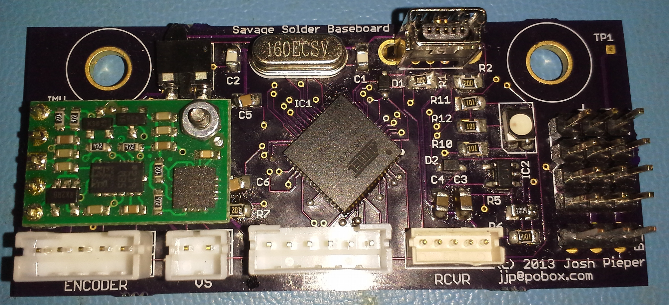
Baseboard fully populated
The board was mechanically designed to fit into an otherwise unused space forward of the steering servos on our Savage Flux chassis. There are two screws there that attach the chassis to some suspension components on the underside. I just replaced those two screws with slightly longer ones, and added a spacer underneath.
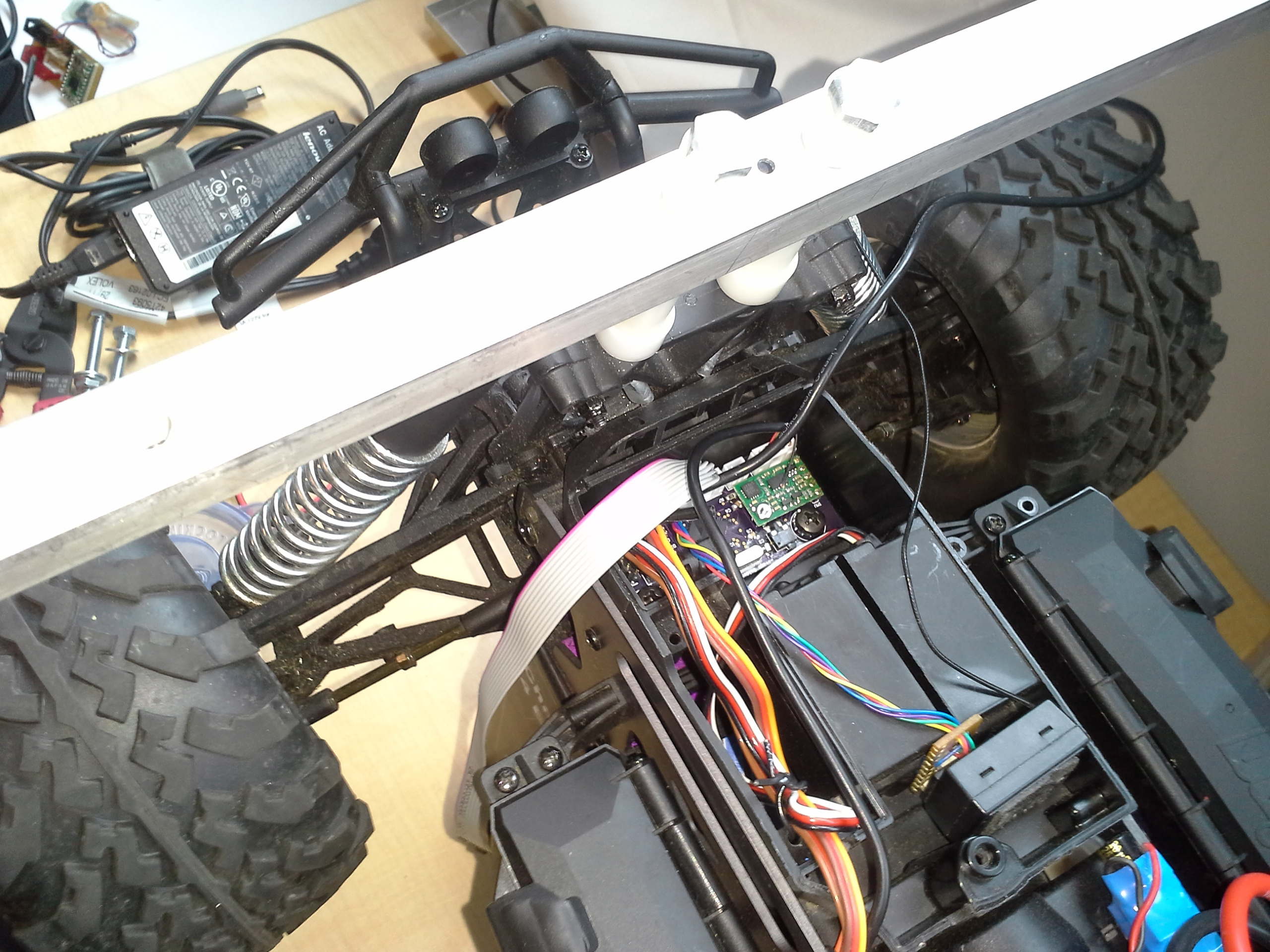
Baseboard installed in Savage Solder
Firmware
As I mentioned before, the firmware was based on that I am creating for the ARR. The basic architecture is the same, in that a master computer communicates with the baseboard over USB, and the baseboard provides high rate servo, I2C communication, and other miscellaneous functionality. I’ve written up the basic servo functionality and engineering test fixture of the firmware previously. Versus our previous controller, the servo control is much improved, both in the precision and accuracy of input and output, as well as having access to more channels. While the firmware supports 8 input and 8 output channels, the Savage Solder baseboard only has 3 inputs and 4 outputs routed to any connectors.
I added a few new pieces of functionality to make the firmware usable for Savage solder, namely:
- Configurable Emergency Passthrough / Override: The controller can be configured with two very short functional scripts which can be used to evaluate various servo and GPIO conditions. One determines whether all servos should be placed in the pass through configuration, and the other determines if computer control should be allowed. These allow both for the Savage Solder emergency safety scheme, as well as any I will use on ARR in the future.
- Encoder operation: Savage Solder uses the sense leads from our sensored brushless motor as an encoder. The firmware measures these to report total distance traveled. Versus the old firmware, it now counts in true quadrature, giving 4 times the resolution.
- GPIO operation: The board exposes control and sensing of a few general purpose input and output pins. They are used to control the LEDs on the board, sense the onboard emergency override button, and sense the bump switches we use for robomagellan style competitions.
Testing
The baseboard has been installed in the car since late July 2013. Yes, this post is very belated! In that time, it has been used for all of our testing and appears to be working quite well. Or rather, it hasn’t been the source of any problems yet!