ARR: Platform Controller
The first aspect of my autonomous helicopter project I tackled was to validate the feasibility of an AVR microcontroller based low level platform controller (more specifically, the AT90USB1286). The platform controller needs to provide the real time interface between the radio receiver, the servos, the primary flight computer, as well as a couple of additional sensors. More specifically, the platform controller has a couple of responsibilities and/or requirements:
- Receive up to 8 channels of servo commands from the radio receiver.
- Emit up to 8 channels of servo commands to the various servos and motors on the helicopter.
- Optionally allow the receiver commands to pass through to the output, or alternately put the outputs under computer control.
- Communicate with a variety of I2C devices, notably the inertial sensors and a barometer.
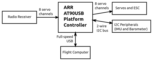
- Expose all of these sensors to the flight computer over a full speed USB connection.
A block diagram showing the interconnections in the current design is below
The servo command manipulation is particularly challenging. As a refresher, most RC servos are controlled with a pulse width modulated signal, where a pulse of between 1ms and 2ms is emitted at 50Hz. 1.5ms commands the center position and the other two extremes are at 1ms and 2ms. The Spektrum receiver on my Blade 450 claims to have 2048 bits of resolution. That indicates that each least significant bit (LSB) of command corresponds to (2ms - 1ms) / 2048 = 488ns. Given that most AVRs have a maximum clock rate of 20MHz, that works out to about 9 AVR clock cycles per LSB. In general, sampling an input with that level of accuracy would require a hardware capture register, but no AVRs have 8 separate inputs which can trigger captures.
Input Approach 1: Analog Comparator and Timer1 Capture
I explored two mechanisms for getting around that shortcoming. First, while the AVR does not have 8 separate inputs which can simultaneously be connected to a capture register, it can be configured to allow the analog comparator to trigger captures. Subsequently, the analog comparator can be driven by the analog multiplexer, which on the AT90USB conveniently has 8 inputs. The downside is that only one input can be selected at a time. This isn’t necessarily a showstopper, as most RC receivers actually drive the servo commands one after another in time. Channel 1 is pulsed, then channel 2, channel 3, and so on. Then when the time for another 50Hz cycle begins, the cycle starts afresh.
My experiments with this approach were mixed. The accuracy was very good, since the capture was done by the AVR hardware, I could accurately sample at 20MHz when each pulse started and stopped. There were downsides though. For one, the receiver servo outputs had to be connected in exactly the correct order. If they weren’t, then the wrong pin would be configured when it was being pulsed. While the pin orderings will be fixed in this application, the firmware may be useful in a more general sense later. The need to whip out a scope to find out which order the pulses are emitted in could be a little burdensome. Second, and more critically, all of the processing for this approach was done in a main loop, including switching which input pin was being sampled. This was done to minimize the amount of time with interrupts disabled in order to support accurate servo pulse outputs. Because of this, occasionally the main loop would not complete a full cycle between when pulse N stopped, and pulse N+1 started, and the pulse would be missed, along with the rest of the pulses that cycle. Similarly, it requires that disconnected channels be placed altogether at the end. While these limitations may not be showstoppers, I wanted to see if I could do better.
Input Approach 2: Pin Change Interrupt
The second approach was to sample the servo inputs by placing them on the AVR’s 8 bit pin change interrupt port and configuring that interrupt. Then, the interrupt handler samples the current value of a timer, enables interrupts, then samples the state of the input port. Both values are stored into a ring buffer for consumption by the main loop. This approach requires about 16 instructions to execute in the interrupt handler before interrupts are re-enabled, which could introduce ~1 LSB of jitter into the output pulses if the timing is unfortunate. However, it can handle servos connected in any order and can handle any input being disconnected. This approach seemed relatively promising, my experiments proved it out with roughly the above properties.
Servo Outputs
Next, the AVR needed to generate the 8 channels of output in an accurate way. The technique that ended up working well for me was to, in the main loop, start a servo pulse output and begin a countdown timer in a small critical section protected with interrupts disabled for 3 instructions total. Then, the interrupt handler is hand coded in the minimal amount of assembly to zero out all the outputs on the given port. gcc by default, if you write:
ISR(TIMER3_COMPA_VECT) {
  PORTC = 0x00;
}
Will generate 12 instructions of prologue and code to save the status, r0 and r1, xor r0 with itself to generate a 0, then store r0 to PORTC, and finally restore everything. What I ended up using was:
ISR(TIMER3_COMPA_vect, ISR_NAKED) {
  asm("push r16"     "\n\t"
      "ldi r16, 0"   "\n\t"
      "out %0, r16"  "\n\t"
      "pop r16"      "\n\t"
      "reti"         "\n\t" :: "M" (_SFR_IO_ADDR(PORTC)));
}
Notably, there is an AVR instruction to directly load an immediate into a register without affecting the status register, so it doesn’t need to be saved. Also, only one temporary register is required, whereas gcc prepares two for no good reason. This hand assembly requires a mere 5 instructions, significantly reducing jitter coupling into the input sampling loop.
Next Steps
Next time, I’ll look at how I stress tested this solution to verify that it would actually work over a long period of time and through all the required scenarios.