Functional gimbal stabilized Mech Warfare turret
Well, that took longer than I expected! I last showed some progress on a gimbal stabilized turret for Mech Warfare competitions more than six months ago. Due to some unexpected technical difficulties, it took much longer to complete than I had hoped, but the (close to) end result is here!
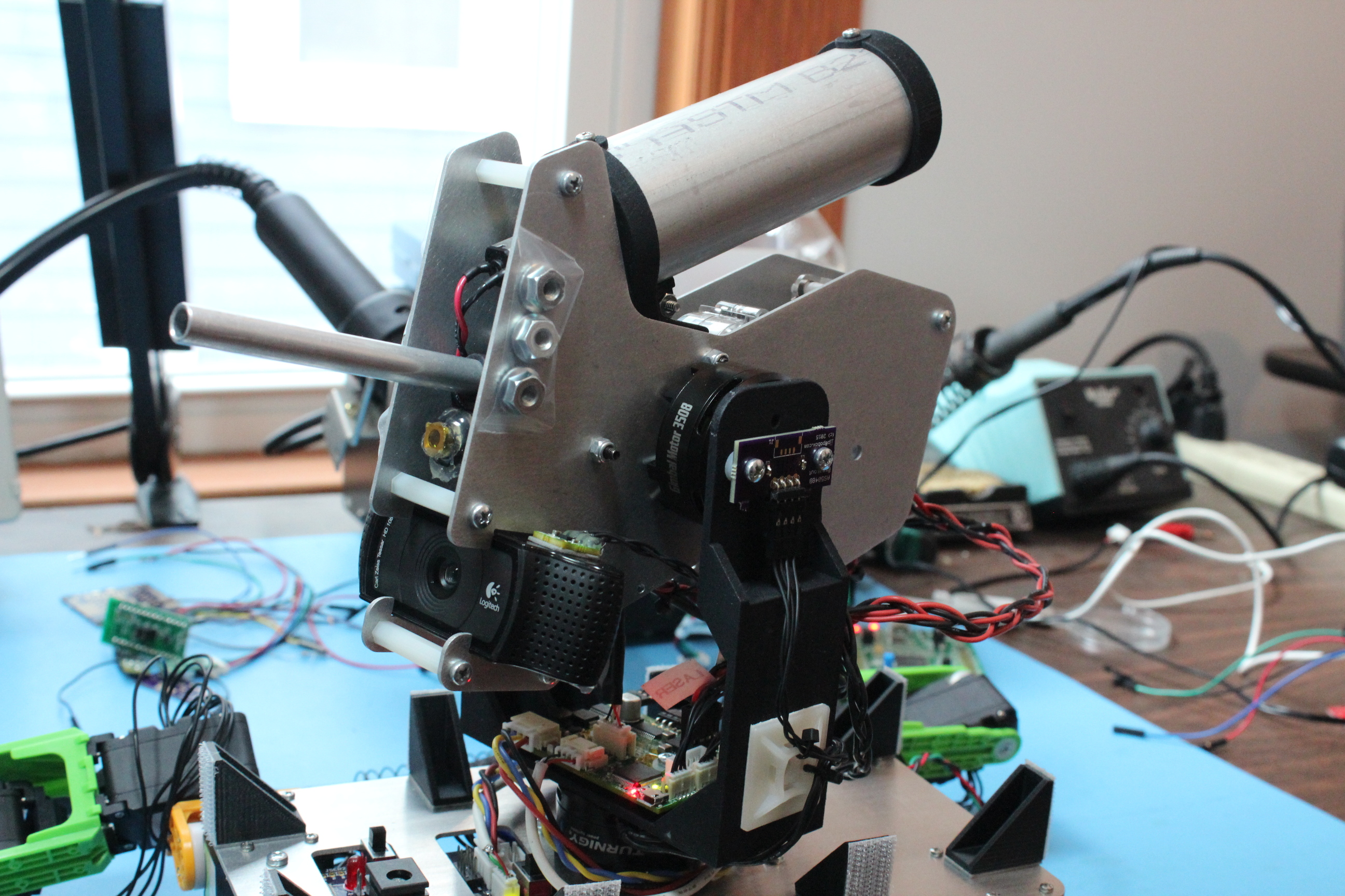
Complete gimbal mounted turret
Here’s a quick feature list:
- 2 axis control: Yaw and pitch are independently actuated.
- Brushless: Each axis is driven by a brushless gimbal motor for high bandwidth no-backlash stabilization.
- Absolute encoders: Each axis has an absolute magnetic encoder so that accurate force control can be applied to each gimbal, even at zero speed.
- Fire control: High current outputs for driving an AEG motor, an agitator motor, and a low current output for a targetting laser are present.
- 7v-12V input: Supports 2S-3S lipo power sources.
- 12V boost: When running from 2S lipo, it can boost the gimbal drive up to 12V for additional stabilization authority.
- HerkuleX protocol: The primary control interface uses a native Dongbu HerkuleX protocol; support for other UART based protocols which will work at 3.3V CMOS levels should be easy.
- USB debugging support: A USB port is present to return high rate debugging information and allow configuration and diagnostics to be performed.
- Open source: All design and firmware files are Apache 2.0 licensed on github: https://github.com/mjbots/mjmech/tree/master/hw/gimbal.
You can see the turret’s basic operations in a quick video here:
Design
The design is driven by the bill of materials selection. The primary components of the gimbal are as follows:
- Turnigy HD 3508 Gimbal Motor: Both axes use this gimbal motor from HobbyKing, which has sufficient power to stabilize a 600g turret.
- Frame: The mechanical frame is a shapeways strong-and-flexible printed part.
- STM32F411: A fast 32 bit microcontroller with support for all the peripherals that are necessary.
- TPS62172: The primary 3.3V regulator which powers the microcontroller and all the other 3.3V parts.
- TPS55330: The 12V boost regulator, which when enabled, powers the gimbal motors.
- MC33926: A 2 channel motor driver used for fire control, it powers both the AEG and agitator motor outputs.
- DRV8313: 2 of these integrated BLDC drivers power each gimbal motor.
- AS5048A/B: These absolute magnetic encoders are used to measure the actual position of the pitch and yaw gimbals.
- BMI160: This IMU is used as the primary source of inertial compensation data. The board hardware supports a second IMU, to be placed on the main robot, but the firmware does not yet support that configuration.
Boards
This gimbal design contains three custom boards, a breakout board for the BMI160 IMU, a breakout board for the AS5048B magnetic encoder sensor, and the primary board which contains the rest of the logic.
BMI 160 Breakout
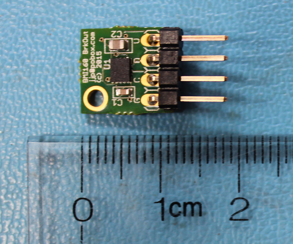
Completed BMI160 breakout board, Assembled by MacroFab
The first board is simple; it is a basically just a breakout board for the BMI160 inertial sensor. It provides the BMI160 itself, some decoupling capacitors, and a 0.1 inch 4 pin connector for the I2C bus.
I had these prototypes made at MacroFab which I highly recommend as a great provider of low-cost turnkey PCB assembly.
AS5048B Breakout
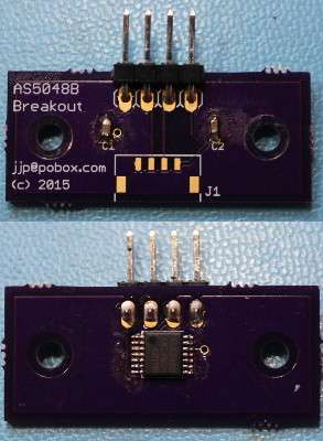
AS5048B breakout board
This, like the BMI160 breakout board, just has decoupling capacitors, the chip itself, and connectors. It additionally has mounting holes designed to fit onto the 3508 gimbal motor. This was printed at OSH Park and hand-assembled.
Gimbal control board
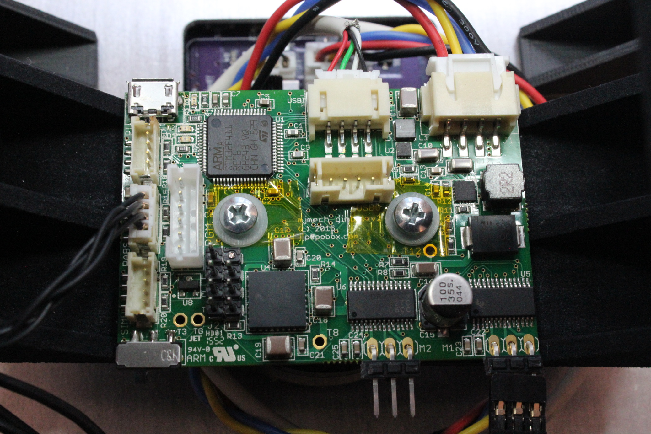
Completed primary gimbal control board (r2) , Assembled by MacroFab
The primary gimbal control board contains most of the system functionality. It is designed to mechanically mount directly above the yaw gimbal motor, as the yaw absolute magnetic encoder is in the center on the underside of the board.
This prototype was also built at MacroFab, who did an excellent job with this much more complex assembly.
The connectors and features are as follows:
- Power and Data: A 4 pin JST-XH connector in the upper right brings in power and data from the main robot.
- Debug USB: A debugging protocol is available on this micro-USB port.
- Camera USB: Two 4 pin JST-PH connectors provide a convenience path for the camera USB. The turret’s camera connects to the top connector, and the main robot connects to the side facing connector.
- I2C peripherals: 3, 4 pin JST-ZH connectors have identical pinout and connect to external I2C peripherals. These are used for the primary IMU, the pitch absolute magnetic encoder, and the optional secondary IMU.
- Arming switch: This switch is connected directly to the enable pin on the MC33926, and is also connected to an input on the STM32F411.
- Programming connector: The 6 pin JST-PH connector has the same pinout as Benjamin Vedder’s VESC board, and can program and debug the STM32F411.
- Weapon connector: A 2x4 0.1 inch pin header has power lines for the AEG drive, the agitator drive and the laser. It has an extra row of pins so that a blank can be used for indexing.
- Gimbal connectors: 2, 3 pin 0.1 inch connectors power the yaw and pitch gimbal brushless motors.
Firmware
struct Config {
  uint8_t address = 0xd0;
  uint16_t rate_hz = 800;
  uint16_t gyro_max_dps = 1000;
  uint8_t accel_max_g = 4;

  Euler offset_deg;

  template
  void Serialize(Archive* a) {
    a->Visit(MJ_NVP(address));
    a->Visit(MJ_NVP(rate_hz));
    a->Visit(MJ_NVP(gyro_max_dps));
    a->Visit(MJ_NVP(accel_max_g));
    a->Visit(MJ_NVP(offset_deg));
  }

  Config() {
    offset_deg.yaw = 90.0f;
  }
};
Sample configuration structure
The firmware was an experiment in writing modern C++11 code for the bare-metal STM32 platform. Each module interacts with others through std::function like callbacks, and the entire system is compiled both for the target, and the host so that unit tests are run. Dynamic memory allocation is this close to being disabled, but it was necessary for newlib’s floating point number formatting routines, which just allocate a chunk of memory the first time you use them. Otherwise, there is no dynamic memory used at all.
It relies on a CubeMX project template for this board. Most of the libraries CubeMX provides have too little flexilibity to be used for this application, so much of the bit twiddling is re-implemented in the gimbal firmware. CubeMX is great for configuring the clock tree and pin alternate functions however, especially in a complex project like this.
Both configuration and telemetry rely on a templated C++ visitor pattern to perform compile time reflection over mostly arbitrary C++ structures. Any module can register a structure to be used for persistent configuration. Those structures can be changed through the debugging protocol, and can be written to and read from flash at runtime. Each module can also register as many telemetry structures as necessary. These can be emitted over the debugging protocol either at fixed intervals, or whenever they update.
IMU stabilization
The IMU is converted into attitude through use of a simple complementary filter, in the same spirit as some of Seb Madgwick’s algorithms. This is then fed into a control loop for each axis’s gimbal.
There are three possible modes, the first of which is what I call “open-loop”, and is based on the same principles as the BruGi brushless gimbal, where no absolute motor feedback is available. In that mode, a PID controller operates with the axis error as the input, and the output is the actual phase position of the BLDC controller. In this mode, the integral term does most of the work in stabilization, so the overall performance isn’t great.
The second mode still uses a PID controller, but now the output is an offset to the BLDC phase necessary to hold the current position as measured by the absolute encoders. This effectively makes the output a direct mapping to force applied to the motor, although of course a non-linear mapping. This mode results in much better overall performance and is easier to tune.
Finally, there is a third debugging mode that lets you just hard command specific BLDC phases. This is useful for calibrating the mapping between BLDC phase and absolute encoder phase.
tview
The debugging protocol is partially human readable, but telemetry data is encoded in the same binary format as used elsewhere in the mjmech codebase. tview is the debugging application we use to read that data, as well as configure and control the overall system.
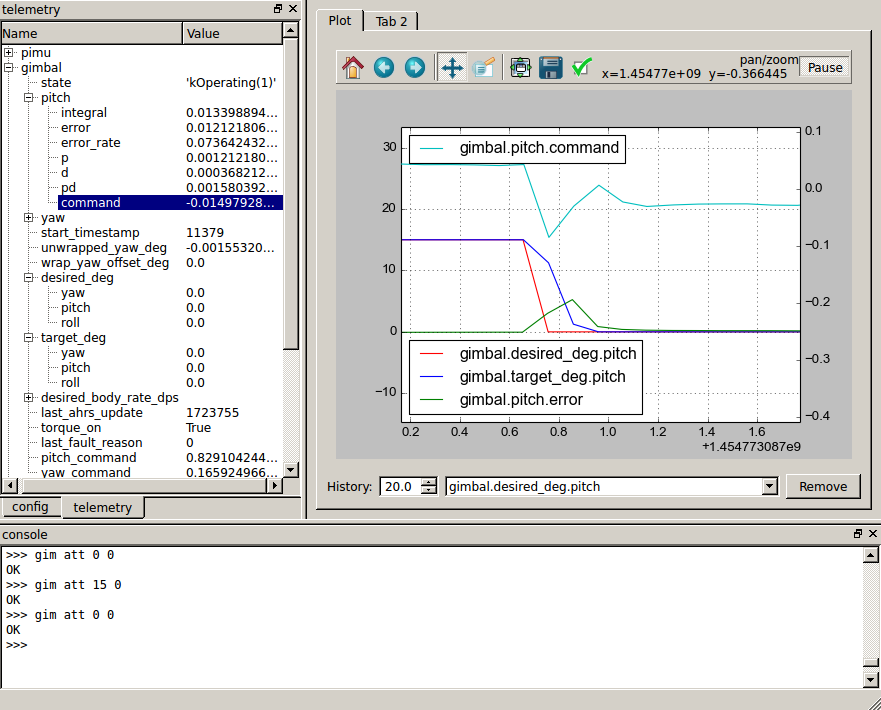
tview window
The bottom pane just has a serial console, where you can send arbitrary things over the virtual serial port. tview directly supports relatively few commands from the debugging protocol, and for instance has no UI to operate the stabilizer or fire control, so for now these are done by hand in that window.
The left pane has two tabs, one with a configuration tree and the other with a telemetry tree. The configuration tree shows all structures which were registered as configurable, and allows you to change them in the live system. The telemetry tree shows all structures registered as telemetry structures, and reports their values live as the system is operating.
The right pane has a live plot window where any of the values in the telemetry tree can be plotted versus time. It is just an embedded matplotlib plot, so all the normal plot interaction tools are available, plus some from mjmech’s tplot, like the ability to pan and zoom the left and right axes independently.
System video
And last but not least, here is a short video demonstrating the turret stabilizing a camera and firing some blanks at a target as our mech walks around.