ARR: Platform Controller Testing
This is a followup to my last post discussing the initial platform controller feasibility experiments for the ARR, my autonomous helicopter.
We left off last time with a couple of candidate designs for the platform controller and some rough requirements that it needed to meet. What I wanted to do was devise a test procedure that could ensure that it would meet all the functional, as well as performance requirements, preferably over a long period of time.
Basic Functionality Testing
First, the controller has a moderate number of relatively performance insensitive functionality that could potentially regress. This includes things like reading GPIO inputs, configuring what inputs to stream, and communicating over the I2C bus. For these, I created a pyunit test suite communicating with the device over it’s USB-serial interace with pyserial. The suite setup function forces the platform controller to reset, so each case starts from a known state. From there, I created maybe a dozen tests which exercise each piece of functionality and verify that it works as expected.
Input Servo Pattern Generation
Next, the platform controller needs to be able to sample 8 servo channels with sub microsecond precision. To verify this, I needed to generate 8 channels of data which were both a) easily verifiable as correct, and b) likely to turn up most of the likely causes of performance problems. My eventual solution was to create a very simple AVR program running on a separate microcontroller using delay loops which emits 8 channels of servo data with pseudorandom values using a known linear feedback shift register (LFSR) equation. I used a 16 bit LFSR, emitting only the upper 11 bits as the pulse width. Each channel was exactly one LFSR cycle behind the previous one in time, so that for a given 8 pulse cycle, you will have seen 8 subsequent values of the LFSR. This made it pretty easy for the receiver to figure out what the remaining 5 bits should have been, even if there were errors of several LSB (least significant bit) on several of the channels. For example, a few cycles of this pseudo-random data look like:
#        Channel pulse width in hex.
# Cycle   1   2   3   4   5   6   7   8
   1     370 1B8 0DC 46E 237 11B 48D 246
   2     1B8 0DC 46E 237 11B 48D 246 123
   3     0DC 46E 237 11B 48D 246 123 491
This approach has a couple of benefits:
- Each 50Hz cycle is independently verifiable. All you need to do is scan through all possible “hidden” 5 bits and see if any result in a close match across all channels. You can also see just how much error there is on each channel.
- Every channel changes drastically at each cycle. Some problems could be masked by slowly time varying inputs. Since at each cycle, the input changes in a very random way, this isn’t a problem.
- The emitter can run open loop. No test harness communication is needed with the servo control emitter whatsoever. It just emits the random 8 channels of servo data indefinitely.
I wired up this separate AVR to the platform controller on a breadboard, and first added a few simple tests to the pyunit test suite that checked just a couple cycles to verify basic consistency. Once that was working, an endurance test script streamed the input data (along with a representative sample of other data as well to simulate comparable load to the final system), checking each frame for consistency and the number of LSB errors.
Servo Output Performance
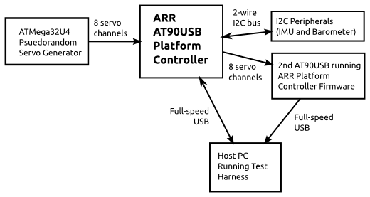
The ARR platform controller has the ability to either pass through servo inputs, or take commands over the USB-serial link. Both of these needed to be verified in a comprehensive way. Fortunately, after the input verification step above, I already had a microcontroller which could sample 8 servo channels with high accuracy and report them back over a serial link! So I solved this by just dropping another ARR platform controller onto my breadboard. The pyunit test suite was extended to communicate with both devices, and monitored the outputs of the device under test using the second system. The final test harness block diagram is below:
Overall System Performance
Using this complete system, the endurance test script verifies not only input performance over time, but output performance over time as well. In one sample run, I got the following results:
 Frames capture: 150,000 (about 50 minutes)
 Input Results:
   Invalid Frames:       0      - 0.00%
   Values w/ 1 LSB off:  5,601  - 0.47%
   Skipped Frames:       0      - 0.00%
 Output Results:
   Invalid Frames:       0      - 0.00%
   Values w/ 1 LSB off:  58,000 - 4.82%
   Skipped Frames:       0      - 0.00%
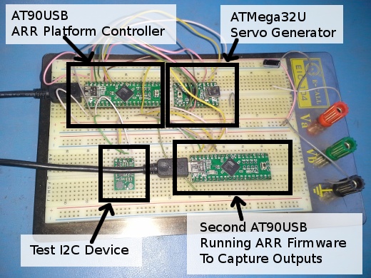
These results were taken when the platform controller was passing through input values to the output and streaming a full complement of I2C data at 100Hz. They are about as expected, a single servo value results in a 1LSB error about 0.47% of the time. Then, passing that channel through to the output and sampling it a second time results in a 1LSB error about 4.82% of the time. Given that 1LSB of error will not even be noticeable in this application, these results are just fine. Finally, for posterity, I’ve included an annotated picture of the completed test harness below: