Tag Archives: servomk2

Ground truth torque testing for qdd100

First, a limited number of qdd100 servos are available for sale to beta testers!  Check them out at mjbots.com.

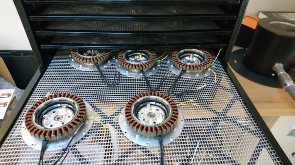
After building up the first set of qdd100 servos, I wanted to empirically measure their performance parameters.  Some astute commenters uncovered in my terrible juggling video, that I didn’t actually have any ground truth measure of torque with these actuators.  Given that the ultimate torque is a pretty useful performance metric, it’s a good thing to have a solid understanding of.

To measure this, I built a simple test fixture (which is also the qdd100 beta development kit), consisting of two brackets.  The first lets the servo be bolted to a table, and the second mounts to the output and has set screws to hold a 1″ diameter pipe.  I used this to insert a 1 meter pipe which then can press against a digital scale.

dsc_0379
1m is pretty long for my workshop!

Then I created a simple C++ application which emitted torque commands in response to joystick input and reported back telemetry from the servo: qdd100_test

Using these I was able to generate a plot of actual torque vs motor phase current:

qdd100 torque vs phase current

There are a couple of interesting things here, one is that the torque constant at low phase currents is slightly lower than I had estimated based on the motor’s Kv rating.  Second, the torque constant drops off faster at higher currents than I had anticipated, and third, the motor Kv rating was lower than I had predicted.  Those things combined result in a peak torque of between 12.5 and 15Nm depending upon the servo.  That’s still enough torque to do some serious jumping, but exploring those discrepancies is now on my backlog.

Here’s a video showing how this testing (and max speed testing) was done:

Building the quad A1

Now that I have a bunch of the mk2 servos set and ready to go, a new leg design, a new power distribution board to power them, and a raspberry pi3 hat to communicate with them, I built a new quadruped!  I’m calling this the mjbots quad A1, since basically everything is upgraded.

dsc_0362

After I initially assembled the new legs onto the chassis, I realized I had the geometry slightly off and there was some interference through part of the shoulder rotation.  I made up new printed parts and replaced everything in front of the camera.  Thus, watch some high speed robot surgery:

The quad A1’s first job is to validate the new moteus controller in the quadrupedal configuration, after which I’ll use it as the primary development platform to get all my gait work done.


Pre-production mk2 servos

To build a second demonstration quadruped and to generate some development kits, I’ve built up a set of 20 of the mk2 servo.  The production process is working out fairly well, in fact slightly better than I had predicted for overall cycle time.  The servos so far are coming out great, moving smoothly with full power.

dsc_0261-1
Shafts inserted into the planet input
dsc_0251
Output bearing on the planet outputs
dsc_0272-1
Planet output and internal gears onto the front housing
dsc_0273
Rotors with bearings and sun gears
dsc_0284
Stators installed
dsc_0300
Planet inputs with planet gears
dsc_0303
Planet inputs installed
dsc_0309
Back housing installed
dsc_0311
Moteus controller soldered
dsc_0313
All buttoned up

Now I need to test these on a quadruped!


Updated leg design for mk2 servo

Since the mk2 moteus servo has slightly different dimensions and a different mounting pattern than my original, I needed up update the full rotation leg design to handle it.  The basic concept is the same, except for some in-progress work on the foot design which I’ll write up later.  The only significant changes were that because of the mk2 design, access to the power and data connectors is much easier.

Here’s a brief CAD snapshot:

20200205-mk2-leg

moteus servo mk2: Reduced weight test

Because my working environment is otherwise too idyllic and peaceful, I’ve been running the new moteus servo mk2 through its paces.  All day long.  8 hours a day.

This is the same test I ran to verify the controller, only now I’ve done it several times longer to get a better feel for if there are any weak links.  Somewhat surprisingly, the ball doesn’t drop all that often, only once an hour or two.

Making the reduced weight servo mk2

Earlier I described my design plan for reducing the overall mass of the moteus servo mk2.  Constructing a prototype of this turned out to take many more iterations and time than I had expected!  Along the way I produced and scrapped two front housings, two outer housings and a back housing.

dsc_0095
Soooo much PocketNC time for naught!

I made one complete prototype which only had the weight reduction applied to some of the parts and lacked a back cover and any provision for a wire cover.  It was the one from the moteus controller r4.1 juggling video:

dsc_0098

dsc_0096-1

Because of the multiple tries on the large-for-me front and back housing, I had to make soft-jaws and prepare stock in a more efficient manner.

I also had to get new workholding solutions for the PocketNC in the form of the wcubed vise.

Design updates

Every one of the pieces got reworked in some manner or designed from scratch for the things that did not exist previously.

Front housing: Here I iterated on how much material to remove from the central cavity.  Initially I removed more, but it gave the primary output bearing problems to be loaded intermittently.  Also, I had adhesion problems with the ring gear when too little material was left there.  I settled on a continuous ring for the output bearing and a decent amount of material for the internal gear.

20200107-front-housing-left20200107-front-housing-right

Back housing: I tweaked the back housing mounting points so that the outer housing could be symmetric.  Also, I added a facility for the wire cover to guard the phase wires entering the controller.

20200107-back-housing-left20200107-back-housing-right

Outer housing: The outer housing was largely unchanged from my initial weight reduced design, although I produced one bad one due to a simple mistake locating the mounting hole, and a second because the stud lengths between the front and back were different in an earlier iteration.

20200107-outer-housing

Planet output: The planet output design changed only to add some weight reducing cutouts.  This was the last part for which I was still using mk1 servo spare parts for, so now I actually manufactured a prototype in house.

20200107-planet-output-left20200107-planet-output-right

Planet input: Here there are now weight reducing cutouts, and the mating studs use less material.

20200107-planet-input-left20200107-planet-input-right

Back cover: The back cover design is basically unchanged, I just had to make one for the first time.

20200107-back-cover-left20200107-back-cover-right

Wire cover: The wire cover is a part of the design I had deferred until now.  It bolts to the back housing and shrouds the phase wires.

20200107-wire-cover-right.png20200107-wire-cover-left

Assembly

Here’s some assembly pictures:

dsc_0093
All the machined pieces prior to assembly


dsc_0099.jpg
Bearings installed in front housing and planet output
dsc_0101
Planet output and ring gear installed
dsc_0103
Stator installed
dsc_0104
Planets installed and pins in planet input
dsc_0106
Rotor and outer housing
dsc_0112
Back housing, controller, and wire cover
dsc_0113
All put together!

DSC00168

DSC00171


Lots of frameless stators and rotors

While gearing up to make some dev-kits followed by a pre-production run of the moteus servo mk2, I recently received a bunch of frameless rotors and stators.

dsc_2225
It’s almost taller than me!
dsc_2228
Some stators
dsc_2230.jpg
A rotor

As with the other custom items, I’ve got some spares of these for sale at shop.mjbots.com if you’re building along with me!  [UPDATE no longer!]

Now it’s time to start building some servos!

wcubed vise for Pocket NC

Just because I’m generally looking for workholding solutions for the Pocket NC, I recently picked up a vise designed for it from wcubed.co.

vise.jpg

Unlike the stock vise that comes with the PNC, this has two movable aluminum jaws.  It can probably hold with greater force than the stock vise, since there is a larger contact area, although the screw mechanism doesn’t necessarily apply the force all that uniformly.  Also, since both jaws are movable, you have to take some care to either manually center things, or do some edgefinding, which isn’t terribly easy on a PNC.

What it does allow though, is clamping narrow things.  The stock vise bottoms out at around 0.5″.  This vise can go all the way down to 0.

That came in handy with some recent moteus servo parts that I wanted to do a “5-axis” style toolpath from 3/8″ thick bar stock.

dsc_0045
Is it really that tall?

The vise provided plenty of clamping power to hold and machine at the tip of this awkwardly long bar.  This cut does chatter like crazy, but that’s about what you would expect.


Preparing stock on a CNC Bridgeport

As mentioned previously, I made up some soft jaws to hold 4in round stock in a 6″ vise.  My goal was to prepare stock for workholding on the Pocket NC v2-50 to machine prototypes of the front and back housing for the reduced weight moteus servo mk2.

Now, I’ve used those soft jaws to trim down both pieces of stock to the correct length, bore a center hole, and in the case of the front housing, remove a bunch of additional material in a more expeditious manner.  There’s not much more to it than that, so here’s the video: