Some time ago I wrote about using the wcubed vise for the Pocket NC. While I don’t end up using it very often any more, mostly because I rarely work with rectangular stock, it can be useful from time to time. Unfortunately, it is no longer manufactured. In case anyone is interested in replicating it, I’ve taken at least a minimal stab at modeling it up based on measurements of my unit along with necessary hardware as picked from McMaster. I suspect the model should be good enough to get something that works.
Note, that there are a number of quirks and annoyances that you’d probably want to fix if you did make more of these:
The main drive screw is an imperial #8-32. Ideally you would use a metric one, as everything else on the PNC is.
The nut that you use to tension is annoyingly small and easy to strip.
There is no reason to have holes for only 2 alignment pins, it might as well have 4 at least.
The bigger problem is that as the jaws are aluminum, you can’t actually apply a lot of clamping pressure before stripping out the threads. But, as long as you keep that in mind, it is serviceable.
With those caveats out of the way, here’s the link!
This is a series, check out the previous posts at part 1, part 2, or part 3. This time, I’m going to make this probe hopefully do something.
I started out just verifying that the Pocket NC would treat the vers.by probe the same as the built in tool setter probe. So I ran a tool measure cycle, and then just tweaked the probe by hand. Woohoo! It stopped the cycle just like normal. Actually measuring a tool worked too if the probe wasn’t activated, or if it wasn’t plugged in. Success.
Probing Scripts
Next, I got a crash course in G-Code. Mostly I used the Linux CNC reference, since that is what the Pocket NC used and all I needed to be interoperable with. Having done no real manual G-Code programming before aside from my limited python auto-generation, I was I guess surprised that there was any real support for in-program scripting. The fun limitations:
Variables can either be “numbered” or “named”. 30 of the “numbered” variables are function local, (and are also necessary for argument passing), and all the remainder are global variables. “named” variables can be global or function local.
All control flow requires human assigned unique integers for each instance of that control flow construct. i.e., an “if-else-endif” chain requires a human assigned integer that is unique script wide to be applied to the if, and its matching elses and end-if statements.
Largely, subroutines need to be in a file by themselves, and all in the same directory.
Annoyingly, expression grouping is with square braces “[]”, not parentheses, “()”.
“comments” are overloaded to also be used for all “non-machine” operations. If you want a comment to actually be a comment, the best and seemingly standard way is to ensure all comments are prefixed with a space.
Some things can be indirected natively, but not for instance, “which axis to move”. That must be specified using a literal character in each command.
The first probing function I needed was to reference the outer diameter of a cylindrical feature. I started by writing a subroutine which would perform a single linear probe in a parameterizable axis. It first probes quickly, then backs off a bit to probe again slowly. To work around the lack of axis indirection, it just uses if-else chains to handle the X, Y, and Z axes.
Next, I used that in an cylindrical feature probing script, where you manually position the probe along one of the major axes at the proper Z probing depth, assuming that the feature is “roughly” at the center of the current coordinate system. It would then probe all 4 axes, finally setting the coordinate system 0, 0 to be the center of the feature. For this, I “simulated” some arrays using the 30 numbered function local variables so that the probing logic could be implemented in a loop.
This did the trick, and now I could reference cylindrical (and square) features using G54.
Repeatability
I ran this around 30 times over the course of a few hours, including remounting the probe a few times and changing the temperature and airflow to get an idea of the repeatability of the probing process.
Axis
Standard Deviation
Peak to Peak
X
0.00031″ (0.0079mm)
0.0012″ (0.030mm)
Y
0.00044″ (0.0112mm)
0.0015″ (0.038mm)
Probing Repeatability
So, roughly around 1 thousandth or 0.02mm of absolute repeatability. I might be able to improve that by tweaking the probing speed or otherwise adjusting parameters, but the Pocket NC itself isn’t a whole lot better so it should be “good enough” for now.
This project is at a functional point for myself, but isn’t quite ready for others to use. The biggest issue is the necessary modifications to the shaft of the vers.by probe, as they aren’t easy to do and require additional equipment. The other pieces also still have some rough edges that should be filed off, including keeping chips out of the RJ45 connectors and getting a PCB in that doesn’t require bodge wires to work.
I also intend to do a little work to demonstrate that the probing can be used to register features across operations properly.
My eventual goal is to eventually get the design to a state where it is nearly “off the shelf” and list it on tindie. To do that will depend upon if I can figure out a better solution for the probe shaft.
In part 1 and part 2, I covered my motivation and the mechanical hardware behind a touch probe add-on for my Pocket NC V2-50. In this post, I’ll cover my prototype electrical hardware.
My intention with the probe was to connect it logically “in parallel” with the existing tool setter probe that the Pocket NC has. I figured that would be likely easiest to integrate with the Linux CNC scripts when I got to the software point. The existing tool setter probe is located in the rotating B axis. That is connected to the Y axis via a single CAT5-ish cable, so my hope was that I could devise something which would pass through the necessary signals on that cable while also paralleling in the new touch probe.
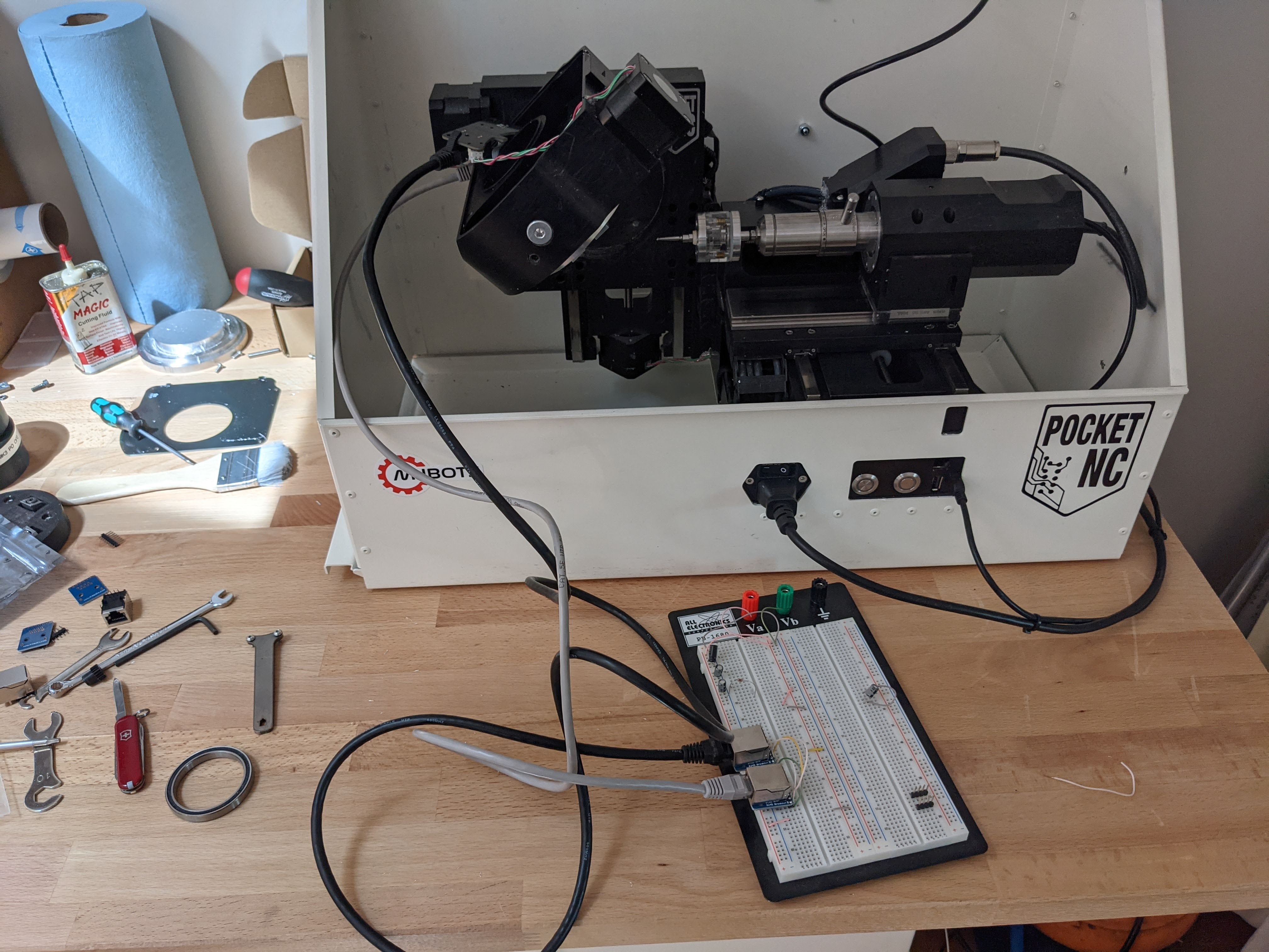
To start, I acquired some RJ45 to .1″ header breakouts from Amazon and broke open the bottom of the Pocket NC B axis table, and wired up a pass through on a breadboard:
Using a multimeter to probe around, it was pretty obvious the first 4 pins went directly to the B axis stepper motor. Of the remaining, 5 was pretty obviously ground. Slightly confusingly, the one that had 3.3V on it appeared to be a pullup for the open-drain normally open tool setter, while the pin with 2.8V on it was the power for tool setter and the B axis hall effect homing sensor. The one remaining pin was the output of the B axis homing sensor.
There were a few electrical challenges here. The first was that the vers.by probe needs 5V, not 2.8V. To begin with, I just wired in 4 AA batteries, and for a longer term solution I picked up a 5V charge doubler from digikey, the TPS60241.
The second required a fair amount of thought: how to make the normally closed vers.by probe act “in parallel” to the built in tool setter, while still being able to disconnect the probe and maintain tool setter functionality. Just inverting the normally closed signal would result in something that made the tool setter appear to be always activated whenever the touch probe was disconnected.
Here, I relied on a design artifact of the vers.by probe. The “USB cable” connector had both D- and D+ connected together, but in the probe itself. So if the probe or cable were disconnected, those two nets would have no connection. Thus I pulled one high, and pulled one low. Then the three states I cared about looked like:
D-
D+
Probe Disconnected
0
1
Probe Connected and Inactivated
0
0
Probe Connected and Activated
1
1
I used a 74HC series NAND gate to only activate a parallel N-FET in that final case, where the probe is connected and activated.
I breadboarded this with the 4 AA batteries, then did a proto-board implementation that used the 5V charge pump too. I was going to use the same SMT components on the proto-board implementation, but the NAND gates, despite being labeled as the same 8VSSOP package as the charge pump, and both from TI, turned out to be a package that was too small for me to “dead bug” solder. So, instead I just flipped over the DIP package NAND I had and wired that up.
The charge pump wired up under the microscopeThe final “proto-board”
Then using some cardboard, hot glue, and a zip tie, I fastened it to the back of the A axis stepper motor on the Pocket NC:
Before I was able to really test this well, a PCB from OSHPark came in, so I used that with a 3D printed enclosure:
Last time in part 1, I talked about why I wanted to add a touch probe to my Pocket NC. This time, I’ll cover the basic hardware necessary to make it happen.
I decided to start with an inexpensive probe so that as I was figuring things out, I wouldn’t be too sad if I smashed it a few times. I’ve seen a number of other hobby machinists use the “vers.by” probes, so I decided to give them a try too.
This probe requires 5V-24V power, has a 6mm shank, and provides a NPN-NC output with a USB connector as the physical connector. Note, it isn’t USB, but just uses that connector for power and the signal.
Mounting
To start with, I needed to get the probe such that I could mount it in the spindle of the Pocket NC. The V2-50 I have can handle a 4mm shank at most, and that is what I primarily use. Obviously, 6mm is bigger than 4mm, so something needed to be done.
So, I wouldn’t be a quality engineer if I didn’t have the brand new toy disassembled within hours of receiving it:
What I ended up doing was turning down the 6mm shaft to 4mm on one of the Artisan Asylum’s manual lathes.
This was pretty challenging. First because the shaft was already permanently mounted into that relatively thin base section, so getting the part trued up in the chuck took some time. Second, because it sticks out so far, I could only take excruciatingly light cuts. In hindsight, I should have worked harder to get the opposite side supported. The entire operation took something like 3 hours. However, when done, I had a probe with a 4mm shaft!
And hey, it fits!
After a bit of tuning with my 2 micron dial indicator, and the provided adjustment screws, it seems to pretty dialed in.
When machining, you need to accurately position the cutting tool with respect to the workpiece. With the stock Pocket NC, there are two methods for doing so. The first is to rigidly locate the workpiece with respect to the B axis reference point using a fixture. The second, is to do manual touch offs. Nearly all of my work so far has relied on the former method, as using a manually touch off on a machine without manual controls isn’t all that precise or pleasant. And while possible, it is tedious to touch off against features more complicated than a single edge.
My Approach So Far
To make that first approach work, I’ve been making 3D printed fixtures (1, 2, 3, etc) to hold the work while simultaneously registering it to the mounting holes or alignment pins on the B axis. Simultaneously, I need to keep the machine well calibrated so that the X, Y, Z, A, and B offsets are all aligned as closely as possible to the center of rotation of the A and B axis.
About the best alignment I’ve achieved between calibration and my fixture is about 50-150 micrometers (2-5 thousandths of an inch). So for any parts or features which need relatively alignment better than that, I need to design it such that all the features can be completed in a single operation without moving the A or B axes.
To date, all the parts for the qdd100 servo were designed with that constraint in mind, so that I could prototype them locally. The rotor and stator need to be aligned with precision approximately 25-50 micrometers, and there are multiple pieces involved in maintaining that alignment, all of which need to be machined accordingly. However, designing the assembly to satisfy those constraints made actually assembling it a relatively time consuming operation, which I would like to improve.
Touch Probes
A third method of workpiece locating, not mentioned above because the Pocket NC doesn’t support it natively, is with a touch probe. A touch probe, is a stylus mounted in the spindle like a tool, which can detect when it is deflected in one or more axes. Then the machine can move the spindle around, and sense where the part is located with respect to the machine coordinates directly.
In this series, I’m going to explore adding a touch probe capability to my Pocket NC. We’ll see how it goes!
My Pocket NC v2-50 is a fine machine for its size class, but there are still plenty of annoyances. One of them is that chips can accumulate places they shouldn’t, either during a run, or over the long term.
There is a cavity near the back of the machine where the Y axis cables and cable guide retract into. That cavity is exposed to chips flying around, so they tend to accumulate there. There is a hole in the bottom of the machine where the chips could maybe fall out, except the hole is too small for any but the smallest of chips, and further, it is completely sealed off when mounted in the stock Pocket NC enclosure.
Basically every time I’ve taken the machine out of the enclosure, I’ve found that cavity so packed with chips that you wouldn’t think the cables could even more anymore. That is even with a thorough vacuuming after every part and often every operation. Plus the Y axis cables are just ethernet cables, which means once you unplug them, those chips can easily fill the RJ45 jacks.
While replacing a failed cable chain, the always responsive Pocket NC support team mentioned that some customers had machined an extra hole in the back of the housing to allow for cleaning that cavity out. Why didn’t I think of that! I did mine with a hand drill and dremel, assuming it would be faster than either disassembling the entire machine or fixturing it assembled into a manual mill. While that was probably true, it was still a painful process.
Despite the pain and the unpolished finish, the end result seems like it will have the desired effect.
I’ve been doing some machining on the Pocket NC lately to prototype some “design for manfacturing” improvements. Some time ago Q at Pocket NC posted that early versions of the v2-50 had a spindle power limit that they later decided wasn’t necessary. My v2-50 was pre-ordered at the launch, so had said limit. There was a procedure for removing it in later versions, which just required removing a single SMT resistor.
WOW! What a difference!
I’ve iterated such that with 4mm single flute tooling and the spindle extension, I was no longer having tool pull out issues, but the maximum MRR (material removal rate) I could achieve was still somewhat limited. My best recipe had 4mm step downs with a 0.2mm width of cut at 750mm/min (about the maximum speed of the Pocket NC). Given that in 6061, I basically always run at that 750mm/min, I measure the MRR as the cross-sectional area, or in that case 0.8mm^2.
With the spindle resistor removed, I’m able to get up to 2mm^2 cross sectional area! In practice, I’m mostly doing 1.6mm^2 to give a little margin, but that is still twice as fast. Granted the Pocket NC isn’t designed as a high speed VMC, but when I’m running parts that have an 8 hr machining time, getting those down to 4hr is a big win.
At this point, other things are the limiting factor. The stock enclosure I have needs emptying every 20 minutes of machining, and when removing large amounts of material across the full work area, you have to clear chips nearly continually from the X axis to keep it from blocking travel near the edge when the chips are flying in inconvenient directions.
When I first acquired my Pocket NC v2-50, I was planning on using it for rapid prototyping of small aluminum parts. I figured with 5 axes, I could do many things with a single setup just clamping from the bottom. However, I was initially thwarted in that plan and had to resort to more creative workholding solutions due to two problems.
First was the vice that came with the Pocket NC. It is serviceable, but provides very little clamping force if you want to hold something that is tall and skinny. For now, while it isn’t ideal, I’m making good progress with the wcubed vise.
Second was the range of Z travel. As shipped by Pocket NC, in order to reach the center of rotation, tools have to stick out something like 35mm. If you want to go beyond, that adds even more. This was a problem, as there aren’t that many tools that can achieve a reasonable material removal rate while sticking out that far, if they can do so at all. This, I’ve finally resolved with this Pocket NC “Q-Tip”:
With that modification, I got an extra ~15mm of travel, which means that I can reach the center of rotation with only 18mm of stickout which is completely reasonable for this class of tools.
Now I can finally “window” machine parts out of a few maximally sized generic blocks of stock with only a single setup. I’ve got 3.5″x3.5″ stock in a variety of thicknesses, which lets me do just about anything, if slowly, without having to worry about workholding.
This summer I had to send my Pocket NC in for some service, when it came back, I immediately noticed that the X axis homing was very far off, something like 0.01 inches, as I was boring a hole in one side of a part, spinning it around the B axis, then boring a countersink in the other side. The two were very clearly not concentric. I suspect the homing mechanism shifted in transport or something, because the error was very consistent.
Pocket NC’s support was great as usual and I quickly received a screencast showing the location of the homing setting:
Step 1: ConfStep 2: ServerStep 3: Launch in New TabStep 4: ConfigureStep 5: Pick AxisStep 6: Change value, select Save, then SytemStep 7: Restart LinuxCNC and Rockhopper
To calibrate the X axis, I just used the hole that was bored all the way through, and manually used the MDI to spin the B axes around and jog the end mill through the center of the hole. Then I used my calipers to measure the offset between the widest part of the mill and each side of the hole. Two iterations of that had the X error back to under 0.001″.
Fast forward a few months and I am running a part where the Y axis zero position matters. Sure enough, it is off too. Not as much, maybe only 0.004″ or so, but enough to make the part not work out. I tried a different technique this time, engraving an X axis line with a chamfer mill in two parts. One part with the B axis at 0, and the other half with it at 180. Any Y offset will manifest as a “jog” in the line.
Several iterations of testingChecking it out under the microscope
I’m not sure if this was any more or less accurate than the boring method, but it was faster and seems to have also gotten me back down to under 0.001 inch of error in the Y axis.