moteus r4.11 has two external connectors, the ABS connector (AUX2) and the ENC/AUX1 connector. The ABS connector was designed initially just to have 2 I2C pins. The ENC connector just has the random pins that were used for the onboard encoder SPI plus one more. Thus the range of external accessories that can be connected is somewhat haphazard and not necessarily all that useful.
When working on a more ground up revision of the controller, I wanted to improve that situation to expose more connectivity options on still a relatively limited connector set. The idea was to use 2 connectors, one which has 5 I/O pins and the other with 4 I/O pins. The onboard encoder SPI would still be accessible on the larger connector to use for at least one external SPI encoder, but how much other functionality could be crammed into the remaining pins? To start, lets see what possible options there are in the current firmware and supported by the STM32G4 microcontroller that moteus uses:
- SPI: The larger connector by definition would have a set of SPI lines, MISO, MOSI, and SCK (now sometimes termed CIPO/POCI and COPI/PICO).
- I2C: I2C requires two lines, one for data and one for clock.
- ADC: Sine/cosine encoders and general purpose ADC inputs require analog inputs.
- Quadrature: Quadrature encoders require two signal lines.
- UART: Asynchronous serial lines can be used for a variety of purposes.
- 5V Tolerant: While the STM32G4 used in moteus is 3.3V native, it can be convenient to support 5V inputs.
To be useful in the moteus firmware, most of these capabilities need to be accessed through STM32 specific hardware. The one exception is quadrature inputs, for which the firmware can manage slow to moderate rates using interrupts alone, but high rates requires hardware decoding. Complicating this, the STM32G4 only provides access to specific hardware peripherals on specific pins through the alternate function map:

My challenge was to figure out which microcontroller pins to assign to the 9 (5 on AUX1, 4 on AUX2) ports which maximized the number of hardware peripherals that could be used on each connector. There are a few additional twists that make this process more challenging than one would expect.
Multiple STM32 pins per connector pin
It is possible to connect multiple STM32 pins to the same external connector pin. With this, the software for any given user requested configuration can leave the unused pin in a high impedance mode where they will largely not effect the output. There are some constraints with this though, caused by the STM32 architecture.
If a pin without analog functionality is connected to an analog signal, then it has a permanently connected schmitt trigger attached. This will cause undesired behavior and power consumption at certain analog voltage levels. Pins with analog functionality have an additional switch to disconnect this. Thus if a user visible pin is intended to have analog inputs, then all the STM32 pins must have analog functionality.
Similarly, if a connector pin is intended to be 5V tolerant, then every STM32 pin connected to it must also be 5V tolerant.
The analog input pins are sprinkled across the 5 different ADC converters present on the STM32G4. Ideally, the pins would not all use the same ADC, so that the sampling window could fit into the existing ADC sampling time of the main interrupt service routine.
Doing the search
I first attempted to conduct this search by hand, but found that I had a hard time wrapping my head around the possibilities, kept getting lost back-tracking and ultimately could not keep all the constraints in mind at once. So… I wrote a tool! I ended up making a brute-force python script that consumes a simple one-pin-per-line encoding of the capabilities, takes some optional constraints like pins or peripherals to not use, and finds all possible configurations which optimize a metric.
I used this in two separate phases. First I ran it in a mode on the 4 user-pin connector to find a configuration where all user pins were 5V tolerant. Then for the 5 user-pin connector, I excluded the pins and peripherals used on the 4 pin connector, and added the constraint that the non-SPI pins had to be 5V tolerant. The onboard magnetic encoder also connected to these SPI pins is not 5V tolerant, so there was no reason to aim for that here. On this second phase, there were bonus points in the metric for how many other peripherals could be crammed into these 5V tolerant pins, since they could be used even while using the onboard magnetic encoder.
The tool has a few separate classes for each of the constraints. Each evaluates a pin configuration or subset of pins, and returns whether that constraint has been met, is inconclusive, or is impossible to meet. Enumerating the possible sets of pins was slightly complicated because of the optional “pin doubling” that can occur. I ended up using an encoding of the problem that made this not too troubling.
Results
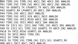
In the end, I met nearly all of my goals. The 4 pin connector looks like:
| Connector Pin | STM32G4 Pin | Functions |
| 1 | PF1 | 5V / SPI / ADC |
| 2 | PA10 / PF0 | 5V / SPI / UART_RX / I2C_SDA / ADC |
| 3 | PA11 / PC4 | 5V / SPI / UART_TX / I2C_SCL / ADC / QUAD_3A |
| 4 | PB7 | 5V / UART_RX / QUAD_3B |
The only real downsides here are that if hardware quadrature is used, then neither USART nor I2C can be used simultaneously.
For the 5 pin connector, the following assignment was chosen:
| Connector Pin | STM32G4 Pin | Functions |
| 1 | PA5 / PB14 | SPI / QUAD_1A / ADC |
| 2 | PB4 | SPI / QUAD_2A / UART_RX |
| 3 | PA7 | SPI / QUAD_2B / ADC |
| 4 | PA15 | 5V / QUAD_1A / I2C_SCL / UART_RX |
| 5 | PB3 / PB9 | 5V / QUAD_1B / I2C_SDA / UART_TX |
Here, the only bonus metric which was not satisfied was having ADC capabilities on the non-SPI pins. Thus to use ADC functionality on the 5 pin port, the onboard magnetic encoder must be disabled.
Conclusion
It probably doesn’t make sense to spend this much time on pin configuration for a purpose built board. In this case, since the number of external peripherals connected to moteus can be relatively large and each end-user may have a different idea of what constitutes a useful configuration, I think it was worth the effort to maximize flexibility of the exposed pins.
