I made a thing!
With that video out of the way, here is a bit more of a write-up!
Motivation
The hoverbot is a simple 2 wheel balancing robot. I built it to demonstrate how the moteus-c1 can be used to drive hoverboard motors and to demonstrate the capabilities of the pi3hat for high rate control and effective attitude reference calculation. It is powered by a single Bosch 18V cordless drill battery and controlled through an identical websocket based interface as the quad A1, primarily operated by a phone with a paired bluetooth joystick.
The entire design is open source and available on GitHub and there is a project page on hackaday:
Mechanical Build
The motors are random ebay ones that I had around to test hall effect encoders with moteus. The listing claimed “Gyroor Swift Hover Brd 6.5″ 36V”, but of course the listing is no longer up. Each was on the order of $70, has a mostly rigid wheel with a little bit of tread, and a mounting stud with a flat to constrain rotation. There are 3 phase wires routed out, as well as standard hall effect encoder connections for what seems to be a 3.3V capable hall effect encoder. I installed MR30 connectors on the phase wires, and a JST GH7 on the encoder to connect it to a moteus-c1.
The robot itself is built from 3d printed parts. All the structural, and some non-structural joins, are comprised of M3 or M2.5 heat set inserts from McMaster pressed into the plastic, and then corresponding bolts that pull into them. Only the moteus-c1 controllers are bolted directly into a 3d printed boss, as there is no mechanical load on them at all.
The frame consist of two primary parts, the “base” and the “chassis”. The base mounts the two motors, the two moteus-c1’s and the chassis. The chassis mounts a Raspberry Pi 4 / pi3hat, a power_dist, and the cordless drill battery.
The base forms a large flat structure. The bottom has a central half-cylinder recess that the hoverboard axles rest in. There are two recesses with bosses to mount the moteus-c1s and the front side has two holes in order to pass wires to and from the chassis. Sprinkled throughout are heat set inserts, which are pressed into place. The motors are each held in place with a 3d printed retaining clamp bolted into inserts, and a protective cover is bolted over the controllers and wiring also into inserts. Finally, the computer and battery chassis is bolted onto the top side into inserts as well.

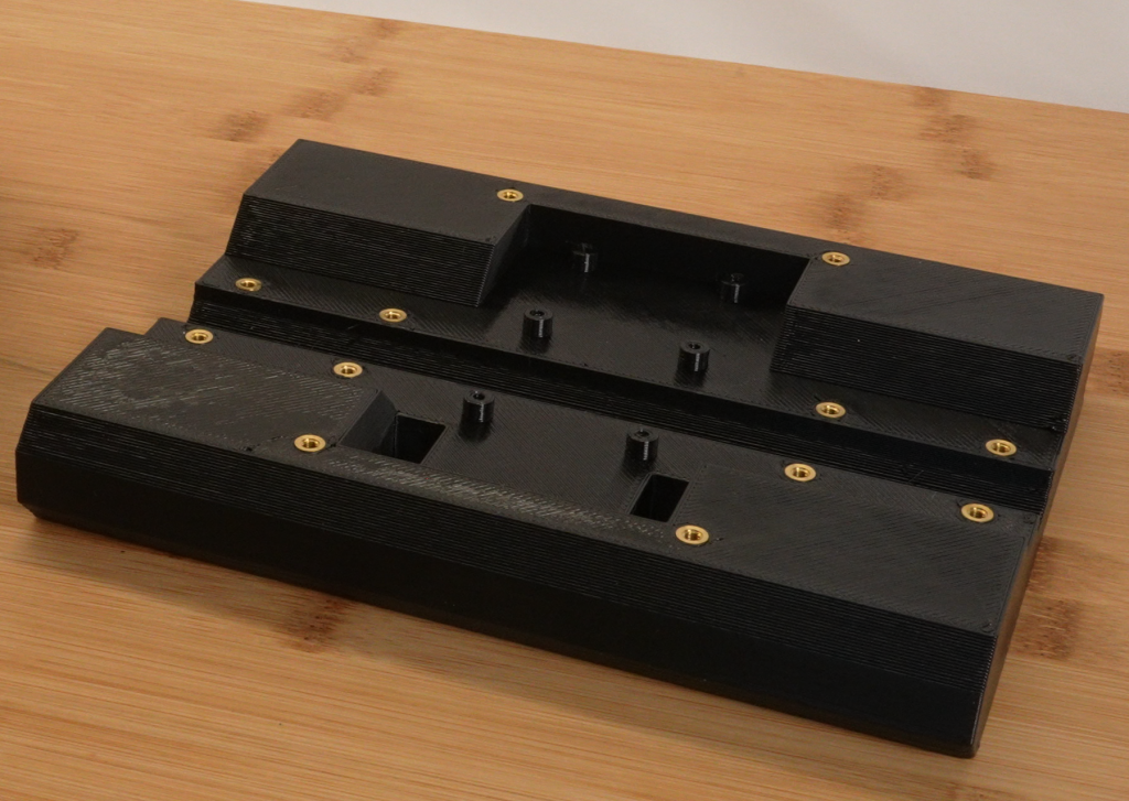
The chassis is the “mast” of the robot. Mounted to the front of it are a Raspberry Pi 4 along with a pi3hat and a power_dist. The back has inserts to attach the battery mounting flanges, and a recess to capture the battery release hinge. There is a hole to allow the power wire to pass from the battery side into the computer compartment. Finally, there are inserts placed to allow a protective cover to be installed on the front.


The battery is a Bosch CORE 18V 4Ah cordless drill battery. There is a small oshpark produced custom PCB with two terminals soldered in place, along with 16AWG silicone wires soldered to an XT90 on the back. 3d printed flanges capture the rail on the battery, and a recess in the chassis captures the release hinge on the battery.


Software
I was aiming for expedience here, so the software started out as a complete clone of the quad A1 repository. That let me use its infrastructure for recording logs and playing them back and a web based monitoring and control panel that lets you drive it from any computer or phone with a gamepad.
I started out by deleting all the files that I knew had nothing but quadruped specific things in it, then went through the dual purpose files and stripped things out as well. Then I got it building again and stubbed out a placeholder for the actual control logic.
Controls
The control diagram can be seen below (with messy computer drawn handwriting):

The inner loop is a pitch PD (proportional derivative) loop and yaw PD loop. The pitch loop operates on the pitch and pitch rate from the pi3hat and outputs a torque that is applied equally to both motors. The yaw loop operates on the “target yaw” and the yaw rate and outputs a torque that is applied with opposite signs to the two wheels. Since the pi3hat does not have an absolute yaw reference, the “target yaw” is just initialized to whatever the pi3hat reports every time control is initiated, then it is advanced at the commanded yaw rate.
The entire pitch and yaw mode control code works out to only two dozen or so lines:

The pitch mode works well after manually tuning a zero point, however it does have some limitations. First, it doesn’t hold a fixed position and will drift along without careful driving. A bigger challenge, is that the pitch mode does not limit the velocity at all. Given the 18V battery, the maximum speed that the hoverboard motors can attain will be easily exceeded, at which point torque can no longer be produced. This results in loss of balance and what I term a USM, or “unplanned slide maneuver”.
To resolve those issues, an outer loop is used that controls the velocity as measured by the hall effect encoders. This is a proportional integrative, or PI controller which uses the average velocity as reported by the two motors as an input, and controls the desired pitch as the output. The integrative term has an anti-windup term, which means that if you push it far enough away, it will drift and no longer hold the original position.
The velocity mode does a great job of holding position, and also provides an easy way to limit the velocity to below the maximum capability of the hoverboard motors, thus fixing the USM problem. However, since the hall effect encoders are coarse, with only 90 ticks per revolution, this control mode is relatively “coggy” when operated at low speeds.
Driving
This robot is a lot of fun to drive! It can accelerate pretty quickly, go up and down relatively steep terrain, go over a fair amount of debris and turf, along with very rapid changes in slope like with drops on the trials course. You can push it around by hand all you want without toppling it. The speed of turns is limited only by what it can manage without tipping sideways.
Granted, there are limitations. The wheels are rigid and there is no suspension. That prevents it from dropping off ledges more than a few inches and limits the traction in slippery terrain. The 36V hoverboard motors paired with an 18V battery sets the maximum speed at around 2 m/s, which is faster than walking, but by no means a run.
