New LCD for Savage Solder
As part of preparing Savage Solder for events this spring, I’ve been overhauling the computer and sensing platform to have higher reliability and lower weight. One of the changes was a new LCD and input interface.
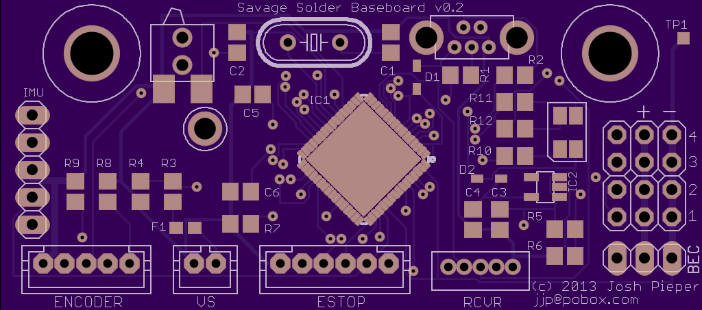
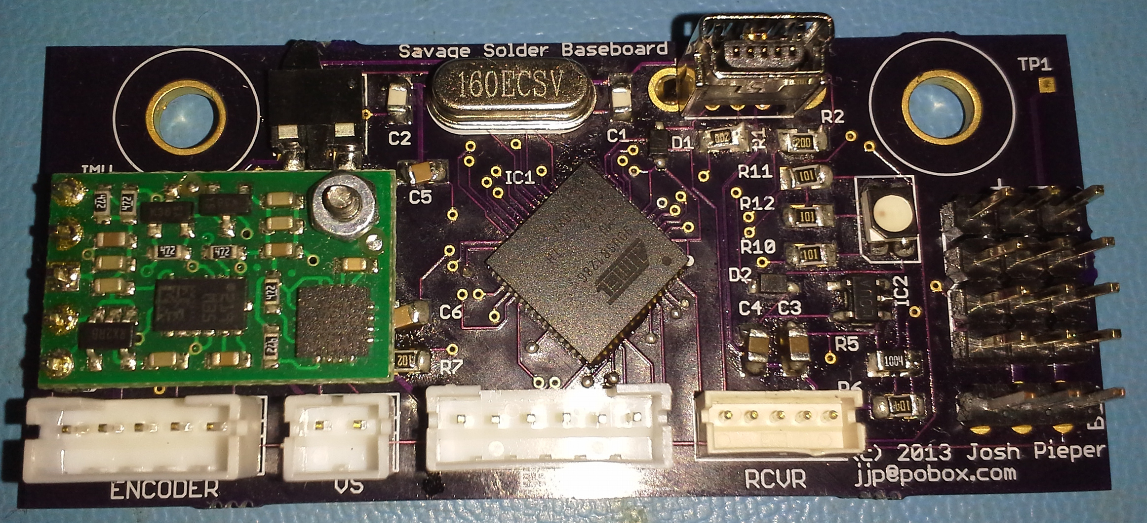
I wrote up the previous LCD here before, which was the width of the car, pretty heavy, and not resistant to the elements. For this version, I wanted to use a smaller screen, and remove the possibility of moisture getting into the case, while still maintaining roughly the same USB interface.
PCB and Assembly
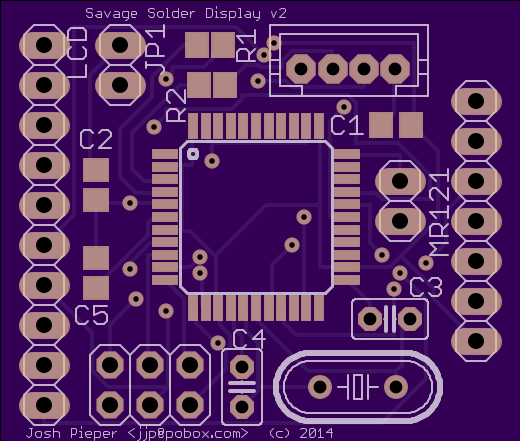
The display I ended up using was the 2.2" TFT LCD from Adafruit. It is color, has sufficient pixels to display everything we wanted, and has a SPI interface. The other half of the solution is the input device, for which I decided to use an off the shelf MPR121 capacitive touch sensor controller, with a breakout board, also from Adafruit.
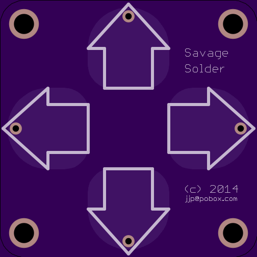
As before, these were glued together with a custom board holding an ATMega32U4 and a few other miscellaneous components. It is mezzanine mounted to the LCD and touch board, and has and external JST connector for USB. Also custom printed was the touch sensor itself. It is nothing more than a PCB with solder-masked copper where each of the touch sensitive areas should be, pulled out to a connector on the back.
The entire assembly was designed to be mounted to the lid of an off the shelf enclosure with a clear polycarbonate lid (which is where the rest of the electronics is going). The LCD and touch board each have four mounting holes, which are attached with a bolt, nut and lockwasher assembly. Sealing is accomplished with neoprene o-rings on the outer surface of the lid.
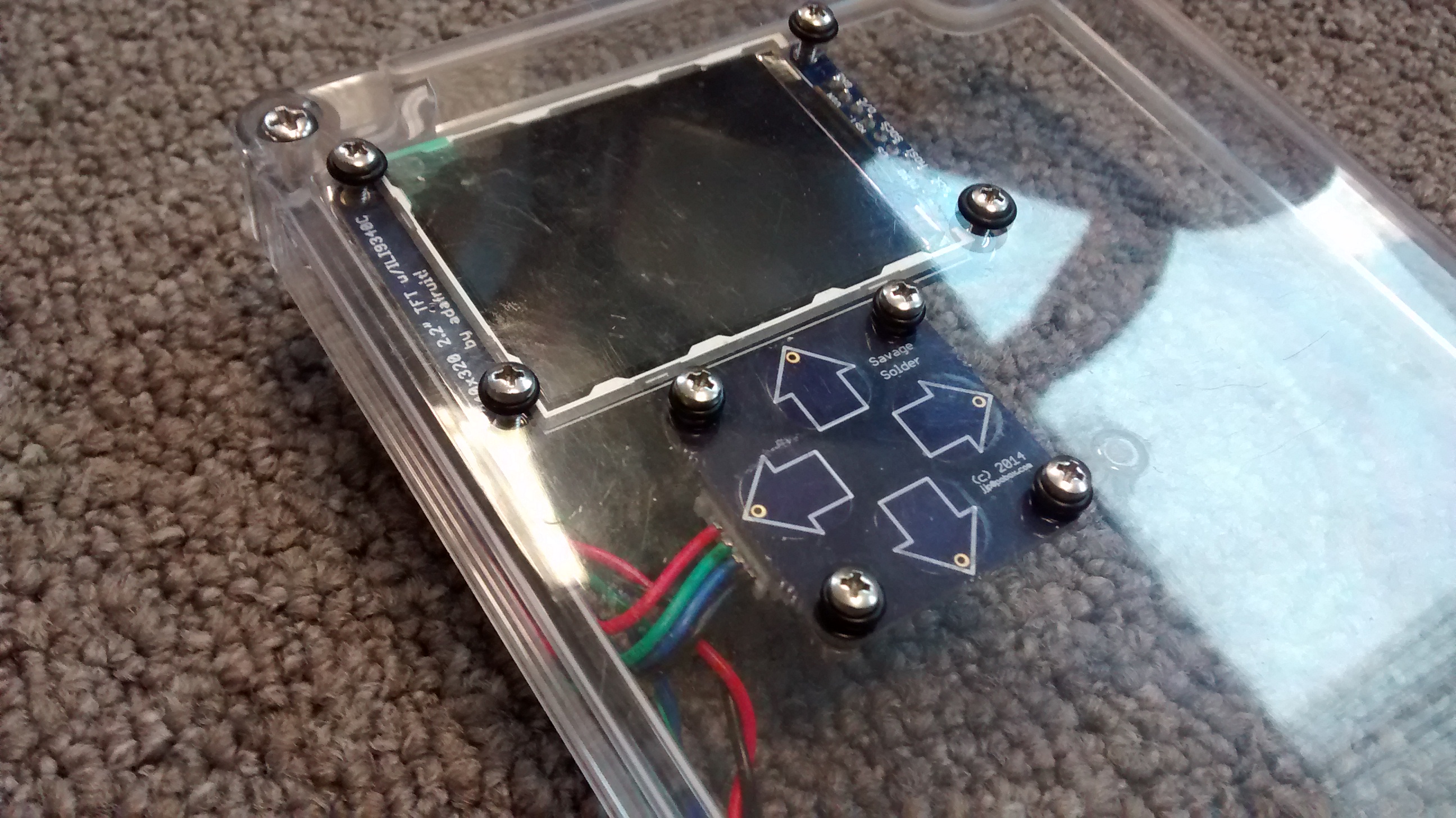
Assembled LCD from front
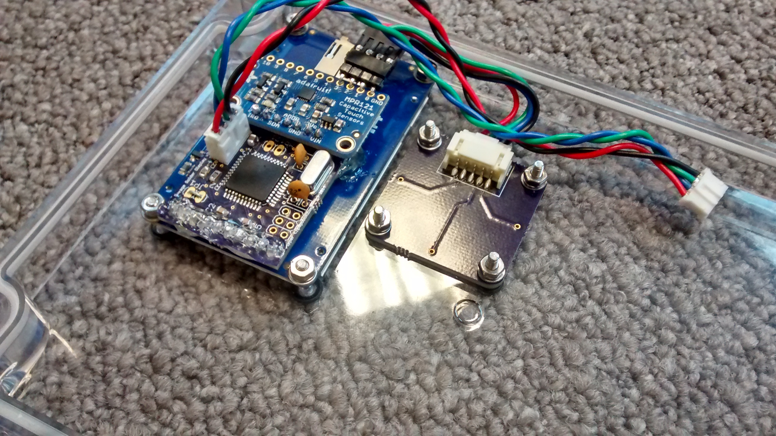
Assembled LCD from back
Software
The MPR121 has a lot of options, many of which influence the performance of the device. The enclosure I am using is an off the shelf one from BUD (PN-1324-C amazon link). It has a polycarbonate lid approximately 1/8" thick, which is kind of at the extreme of what you can get capacitive touch sensors to work through. I was inspired by Adafruit’s MPR121 library, but rewrote it to not require Arduino. I had to tweak a number of the MPR121 constants as well to work under the thick polycarbonate:
| MPR121 Register | Adafruit | Savage Solder |
|---|---|---|
| CONFIG1 | 0x10 | 0x20 (32uA charge current) |
| Thresholds | 12, 6 | 4, 2 |
For rendering text on the display, I also based my code on the Adafruit ILI9340 library. Since this LCD controller has to render text one pixel at a time, it was much slower than the HD44780 text-based controller we were using previously. To get remotely acceptable performance, I had to make the AVR keep a framebuffer around, and only re-draw characters which had actually changed.