Updated power control board for Savage Solder
In our efforts to reduce weight and complexity for Savage Solder, over the Christmas holiday and first couple of months of 2015 we designed a new computer system based on the Odroid U3 instead of the Mini-ITX form factor PC we had used previously.
Functions
To make that happen, we put together a new power control board which was designed as a “shield” for the Odroid. It has the following functions:
- Li-polymer charge management: Previously, Savage Solder used a laptop battery extender, which was functional, but suitable capacities came only in large form factors. We gained a lot of flexibility by using a custom form factor li-poly battery pack, but this means that charge control and safety need to be addressed.
- DC/DC step up regulator: The Odroid (and other things), need 5V, so we have a step up regulator to bring the li-poly voltage up to what the Odroid can use.
- USB hub: The Odroid has 3 USB ports, (4 if you count the OTG port). We need more than that, and there aren’t many small form factor hubs which would fit into a tiny enclosure. This needed to be USB 2.0 high speed, to support webcams.
- Serial level shifter: To reduce the demand for USB ports, we pull out the exposed 1.8V serial port from the Odroid and level shift it up to 5V on a connector that also has 5V power. For Savage Solder, this is used for the GPS.
- Speaker power: The control board has a FET to switch the audio power directly from the li-poly pack.
- Soft shutdown management: The Odroid’s filesystem could be compromised if it gets powered off unexpectedly. We have a low power microcontroller which reads a discrete switch, informs the Odroid, and powers the system off after the Odroid has had a chance to shutdown cleanly.
- **I2C Level shifter:**The Odroid’s expansion port I2C is level shifted to the li-poly voltage level to communicate with the li-poly charger control IC and the shutdown management microcontroller.
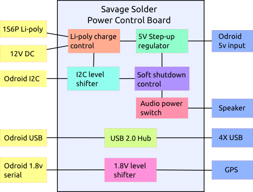
Functional block diagram
Components
These were the primary components that the rest of the board was designed around:
| Part | Manufacturer | Function |
|---|---|---|
| BQ24192 | TI | Li-poly charge management |
| LTC3124 | Linear | 5V step-up regulator |
| CY7C65632 | Cypress | USB hub |
| ATTiny841 | Atmel | Soft shutdown control |
| TCA9517 | TI | I2C level shifter |
| SN74LVC1T45 | TI | Serial level shifter |
PCB
One of our goals with this design was to be pretty sure that the board itself would not be the cause of power problems, signal integrity problems, or really any sort of problems. Thus each USB port’s power is separately switched with a separate large decoupling capacitor and the USB signals have ESD protection. The board itself is 4 layer to give a proper ground plane under each of the USB traces and keep the impedance matched well. All the external connectors with power are separately decoupled and have PTC resettable fuses inline.
As mentioned, the board was designed as a “shield” for the Odroid. That meant that the mounting holes matched up with Odroid’s, and that the Odroid’s expansion port connects through with a stacking connector. Additionally, the USB connection was made by desoldering the Odroid’s vertical USB connector and using another stacking pin header to connect the two boards.
The board was manufactured on OSHpark’s 4 layer process, which worked out just fine for this project.
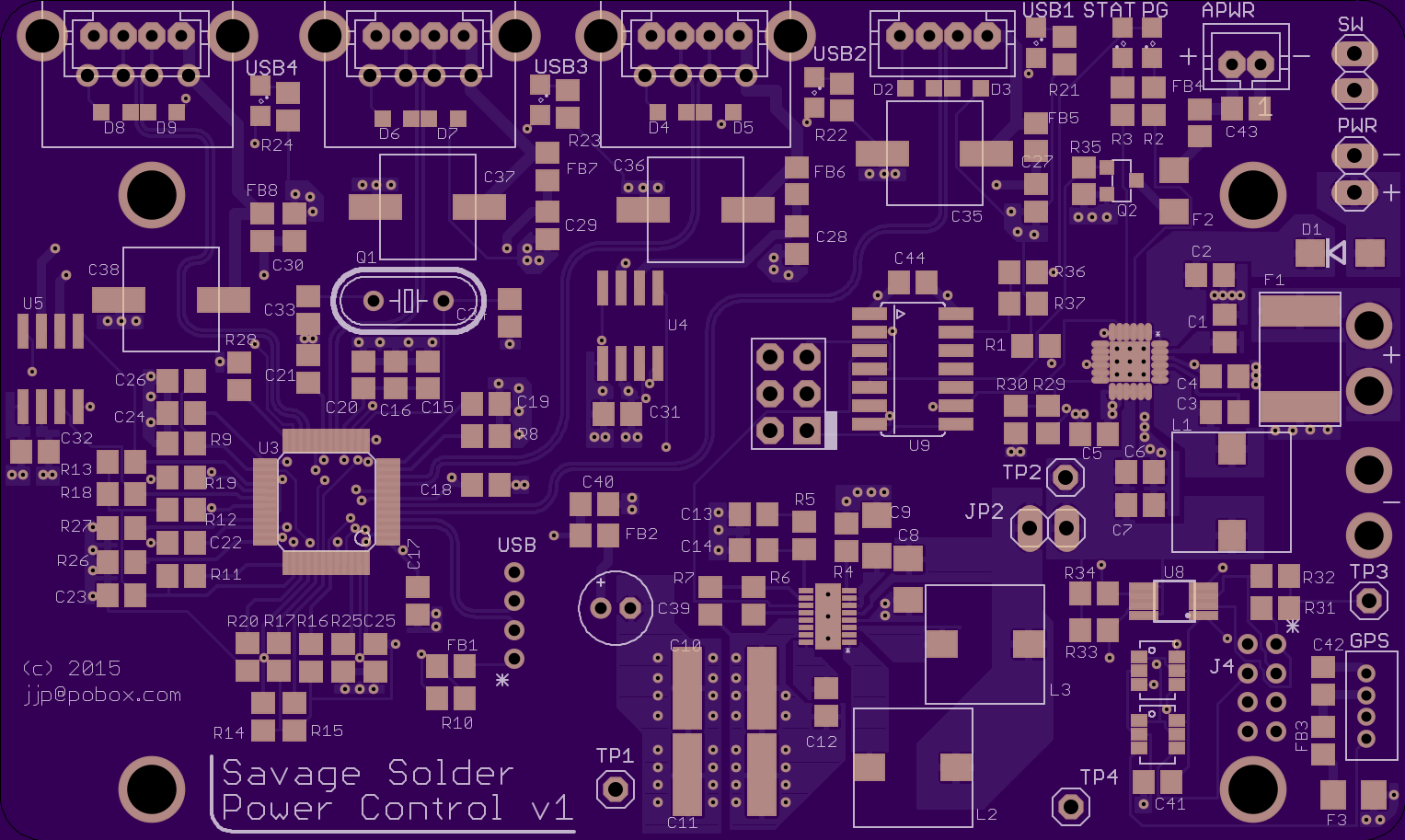
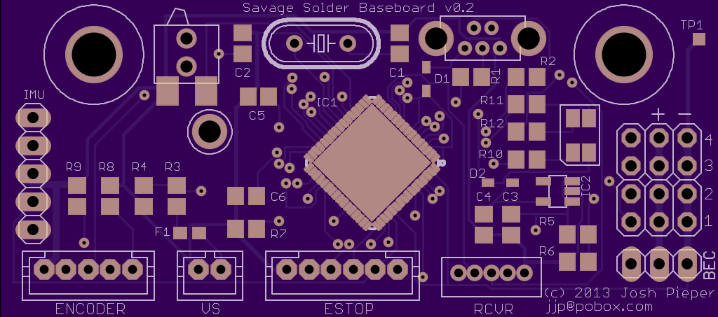
oshpark.com rendering
Assembly was challenging, especially for the QFN parts. The one that we built up so far I assembled by hand, using an iron and a hot air rework station with a lot of retries. If we make a subsequent revision, it will need to be with a toaster oven reflow system, or contracted out. Hand assembly time was probably around 16 hours.
While not strictly on the board itself, desoldering the vertical USB connector on the Odroid was very challenging as well. We ruined one Odroid in the process, and the other needed hand rework to replace some components which were lost in the desoldering process.
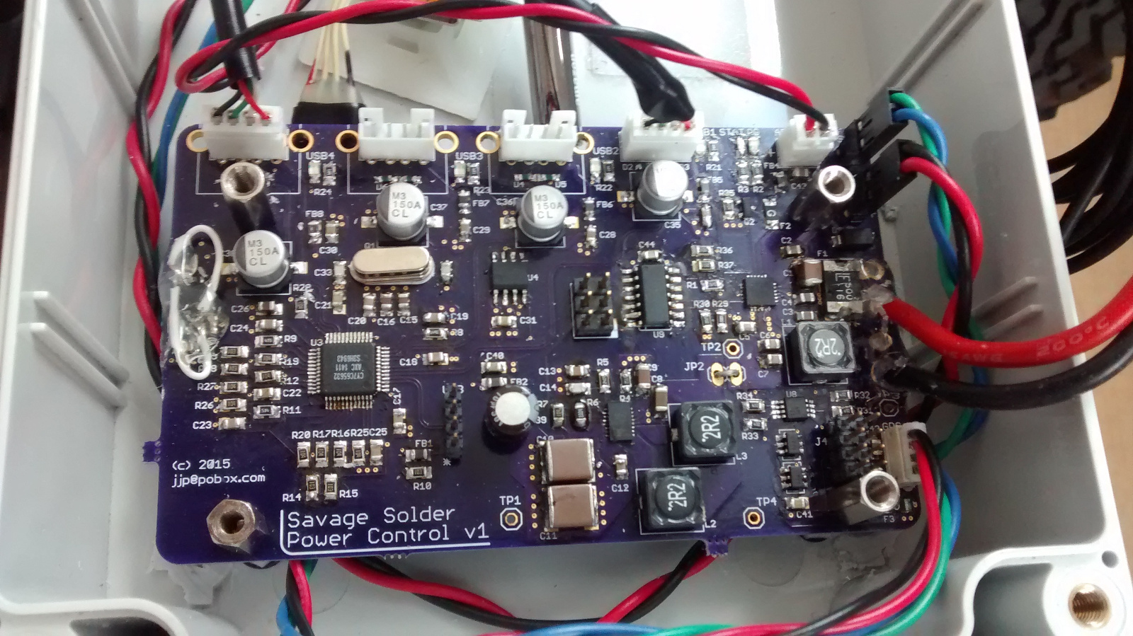
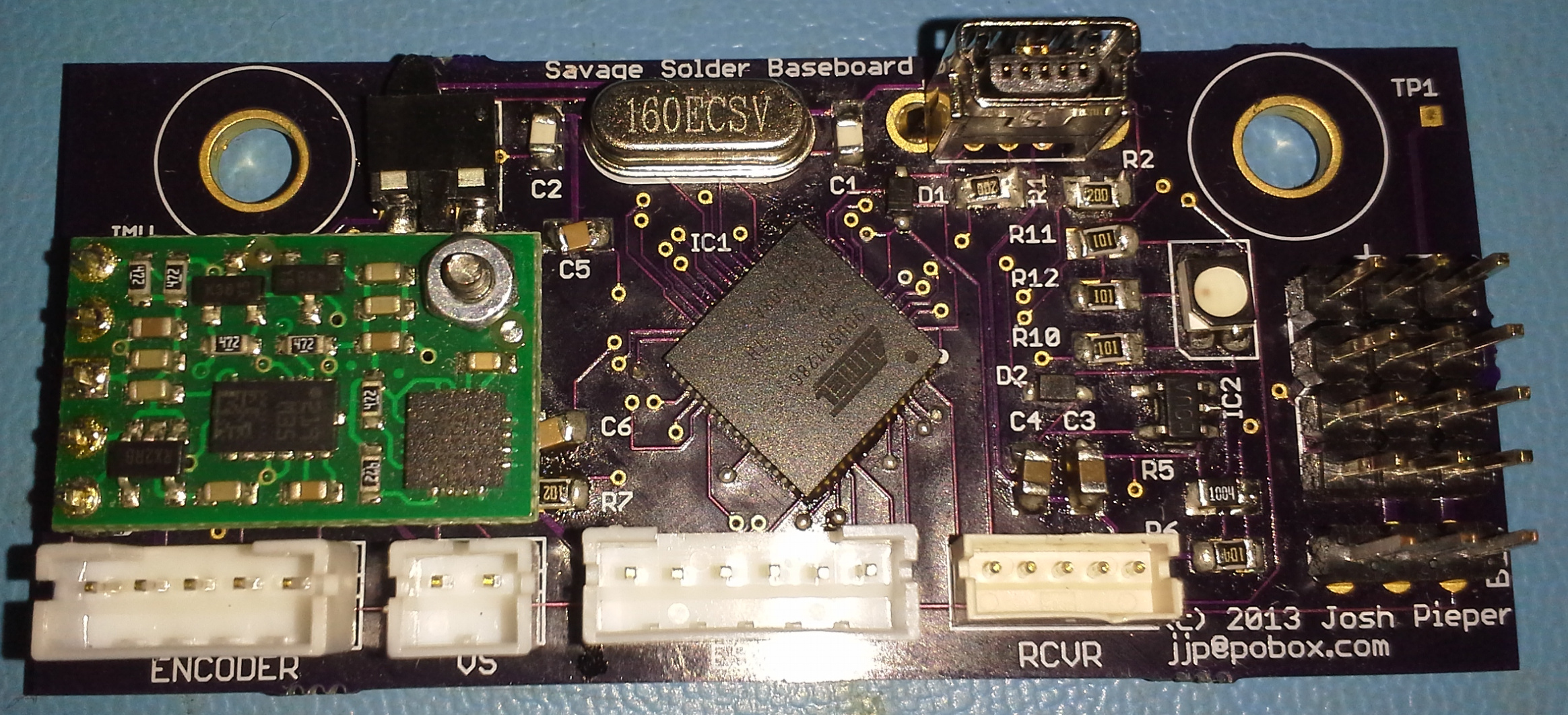
Final assembled board
There are of course a number of errata in the version one board, but nothing that couldn’t be reworked in place.
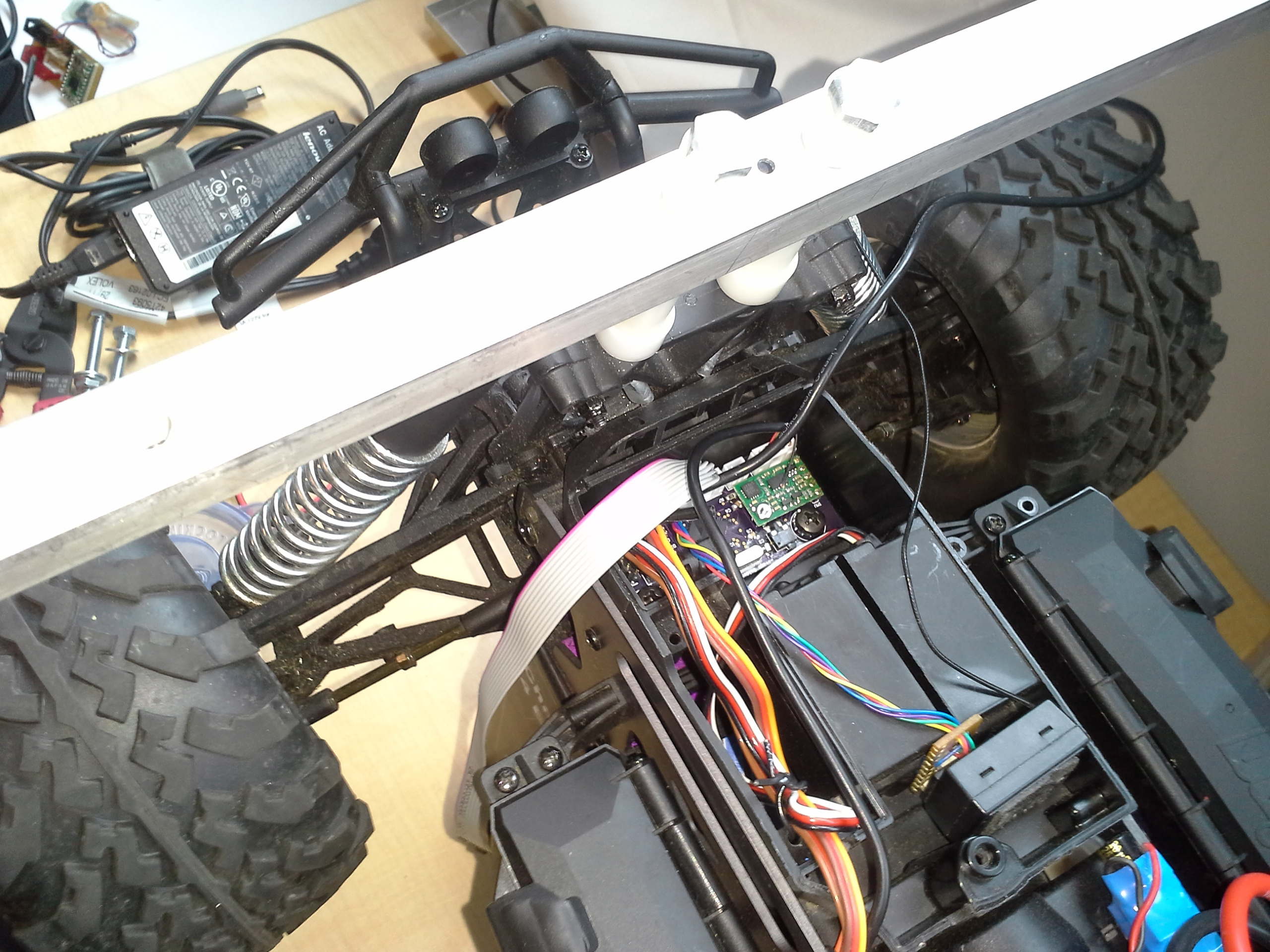
Installation and test
So far, we haven’t identified any performance or reliability problems when testing on Savage Solder. The board ran through our spring testing and RoboGames Robogamellan run without being the cause of any known failures.
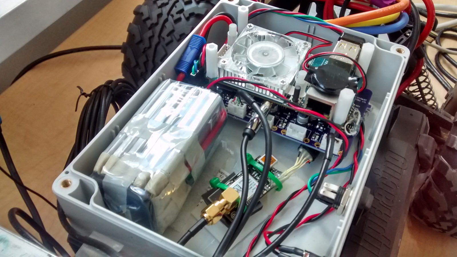
Board assembled in enclosure