Archives: 2012-11

Savage Solder: Transmission Backlash and Pavement Results

In part 1 and part 2 I looked at our progress in improving the acceleration performance of our Savage Solder autonomous racing car as applied to RoboMagellan type competitions. We left off with a reliable open loop model of acceleration versus current speed and throttle input, which were combined with some feedback elements to make a simple controller. However, upon running the controller the first time, we saw some odd behavior when the throttle transitioned to and from braking. It was difficult to see at our standard sampling rate of 20Hz, so we increased our overall control loop to 50Hz (the rate at which the RC servos are updated) to get a better view. The behavior can be seen on the plot below:

20121125-backlash.png

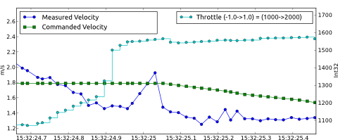
Around time 15:32:24.9, the throttle command switches from a braking command to a positive acceleration. Then just before 25.0, the velocity starts a rapid ramp up for 4 time samples, starting from about 1.4 m/s and peaking at about 2.0 m/s, a 40% increase. After those 4 samples, it snaps back into place at around the previous value of 1.4 m/s. This type of velocity spike occurs on nearly every transition between accelerating and braking.

What is happening here is caused by the backlash in the car’s transmission. There is a region of about 3-4cm where you can move the drive wheels without turning the motor caused by the aggregated slop in all the individual linkages between the motor and the drive wheel. The car is not actually speeding up or slowing down during this event, but the motor (where our velocity data comes from) does. It speeds up until all the backlash is consumed, at which point it then resumes traveling at the exact same speed as the rest of the car. This was confirmed by looking at auxiliary inertial measurement data which indicated that the car itself did not accelerate or decelerate during these events.

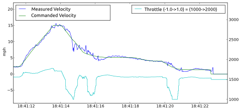
Once suitable filtering was in place to mitigate the effects of backlash, our velocity control is performing admirably on pavement test surfaces. Below is a plot of a demonstration run with a top speed of 15 mph, an acceleration of 3.0 m/s^2, and still decelerating in a controlled manner to bump a cone. With our current tuning, it starts decelerating about 8s before contacting the cone. We were just able to get enough space in our test area to get it to hold 15mph briefly. Note the accurate velocity tracking both during hard acceleration and deceleration, as well as the smooth approach into the final bumping speed.

20121125-savage-fast-plot.png

And finally, video we took of the car when the above data was recorded:


Savage Solder: Measuring Acceleration Characteristics

In the previous installment, I looked at the problems we had with Savage Solder’s legacy PI velocity control loop when used for RoboMagellan type competitions. This time, I’ll look at how we measured the characteristics of the car, motor, and motor controller.

We wanted to get a better understanding of what the open loop behavior of the car was at a range of accelerations – and on a variety of surfaces. So, I fired up our primary application, which just happily logs data from all systems when the transmitter is in manual override mode. Then, I had a lot of fun driving around a bunch. Practically though, I tried to get instances of differing throttle values at as many different speeds as possible. So I tried to accelerate and decelerate at different rates as fast as I felt comfortable going in the space I had to drive. I repeated the process in some grass to get a feel for how the behavior differed there. Finally, I pulled all the data off the car and started the analysis.

My theory was that for a given terrain, speed, and throttle, the car would exhibit a particular amount of deceleration or acceleration. This assumes that the motor controller is stateless, but otherwise encompasses a range of possible motor controller implementations. At each instant in the data file, I measured the instantaneous acceleration by sampling the velocity some fractional time before and after. Then, I created a 2D grid defined by the possible car velocities and throttles, and for each grid cell accumulated the observed accelerations. This average acceleration for each cell was then plotted using matplotlib’s tricontour function. Below I have included a sample plot from pavement and grass driving.

20121123-acceleration-profile.png

Notably, this plot has no information about regions of braking action. It turns out that it was extremely hard to actuate a suitable range of braking actions from different speeds when driving by hand. Instead, we ended up running dedicated experiments where the car started from a steady state known throttle, then commanded a constant braking throttle until the car stopped. I repeated this for a range of braking values, starting from as high a speed as I was able to do in our back lot testing area. The below plot shows those values.

20121123-regen.png

The data pretty much matched the hypothesis. In fact, the acceleration could be accurately modeled using a simple electric motor model where the throttle input directly controlled the voltage applied to the motor when powering forward. A similarly simple model matched the braking behavior. These models were enough to create a velocity controller which can accelerate and decelerate much faster, while still maintaining position accuracy of velocity. However, before we were able to make it work robustly, there was one other annoyance which I’ll discuss in the next post, motor backlash.

Savage Solder: Improved Speed Performance

One of the areas of improvement we are working on for Savage Solder is velocity control. More specifically, we are improving the performance of the velocity controller at higher speeds and higher accelerations. In our runs during the spring of 2012, we had a simple PI controller on velocity let the car safely run around 5-7mph with accelerations around 0.7m/s^2. Given that the underlying platform can exceed speeds of 40mph and accelerations of 4m/s^2, we wanted to get a little closer to the theoretical maximum in order to reduce event times. Here, I’ll look at why the original controller was limited, and what properties we wanted an improved controller to have.

20121121-throttle.png
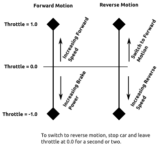
First, a little background. The motor controller on Savage Solder is the stock HPI Savage Flux controller, configured with a sensored brushless motor. For input, it uses a standard RC servo control pulse width signal from 1ms to 2ms in duration at 50Hz. We logically treat it as having a range of throttle command values of between -1.0 and 1.0. In forward motion, the default configuration has increasing positive values used to increase speed, and increasing negative values to apply braking forces. It can also move in reverse, but requires a small lockout window of stopped time, and in reverse, no braking is possible. Forward commands always result in attempting to move the wheels forward regardless of the current directin of motion. You can configure different behaviors, but these are the factory default and most of the alternatives involve removing reverse capability entirely, which we require. When driven manually, the throttle is very sensitive. Given the car’s very fast top speed, it takes very little movement on the throttle trigger to accelerate the car up to speeds that would require a wide open tarmac to navigate safely. Similarly, it takes some skill to not flip the car over end over end during both acceleration and deceleration. The figure at the right gives a simple representation of these properties. Note that the magnitude of the increasing speed and brake power is not specified and in fact the region near 0 throttle is also undefined.

The legacy velocity controller for Savage Solder was a simple PI controller, with a small state machine surrounding it to reset it and wait the required time upon switching from forward to reverse motion. In this formulation of a PI controller, the integrative term “finds” the appropriate throttle over time, while the proportional term improves the dynamic response by applying extra throttle based on the instantaneous error. Given a long time, and a constant speed command, this controller had no problem converging on that speed with precision. The plot below shows some data from the spring where the car accelerates up to 8 mph. You can see that the actual speed converges on 8mph in a second or so.

20121121-naive-pi.png

The problems with this solution became more apparent at higher accelerations. Since the integrative term requires error in order to equalize, the higher the acceleration, the larger the steady state error during the acceleration. This isn’t often much of a problem during cases of speeding up, but when slowing down it can be a big deal. Our approach for the Robo-Magellan competition (and most other entrants), involved bumping the target traffic cones at low speed. If the speed controller lags in deceleration by several seconds, the car would just plow over the cone rather than stop in front of it. The other major problem is during the transition from a regime of constant acceleration to one of constant speed, especially when slowing down. The integrative term can take a long time to wind back down, during which time the car is completely stopped. In the 2012 Robomagellan event, this was magnified by transitioning from pavement to tall grass right near the end of the deceleration into the first bonus cone. Finally, to mitigate these problems somewhat, we set the P gain to be larger than would otherwise be desirable. The result of this higher gain in the plot above can be seen as small oscillations in the speed and commanded throttle.

When designing an improved solution, we considered the two primary event types that we were planning to compete in:

  • Robo-Magellan: As mentioned above, tracking accuracy on deceleration is a must, otherwise the car could overrun the targets. High acceleration and deceleration rates are useful too, as targets are often in close proximity, not leaving much room to speed up and slow down.
  • Sparkfun AVC: In this event, deceleration accuracy is not as important, but top speed and acceleration are. You basically speed up once, and decelerate briefly for each of the 3 turns.

Next time I’ll look at the experimental path we took, and the next iteration of the velocity controller which we used to improve the performance.

New Project: Autonomous Racing Rotorcraft

20121114-blade.jpg
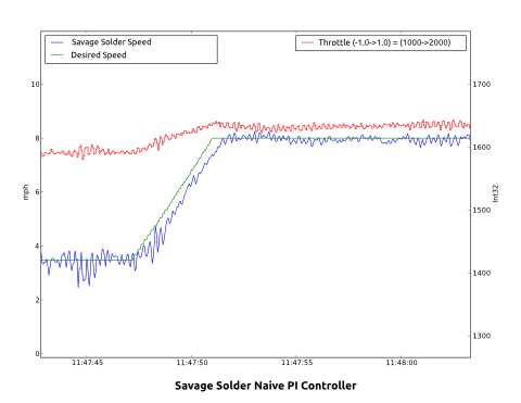
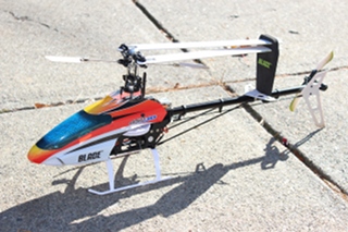
For the last 6 years I have ever so slowly been learning how to fly medium sized RC helicopters outdoors, in an attempt to become a good enough pilot that I could roboticize one. About a year ago I upgraded to a Blade 450, which let me practice outdoors in a much wider variety of weather conditions and provided for a feasible amount of payload. My proficiency is now good enough that I’ve started work on the control and navigation design with the medium term goal of entering it in autonomous racing competitions, such as Sparkfun’s AVC.

At the top end, this helicopter can lift around 100g, which while tight, should be completely doable with 2012 componentry. A rough outline of the components I have in mind now is:

  • Computer - IGEP COM Module: A gumstix clone out of Spain, they are slightly smaller, slightly more powerful, and can nominally be powered and operated over USB with no baseboards required. (Although I’ve so far found that heat issues pretty much require a baseboard or other heatsink of some kind be used.)
  • GPS -Sparkfun GS407: We had reasonably good luck with the u-blox 6 chipset on Savage Solder. It doesn’t have great precision, and has no way to bypass the internal EKF, but at least lets you configure it somewhat.
  • IMU - Currently I’m planning on using the same chips as in the Pololu MinIMU-9 v2 just because I’ve worked with it on Savage Solder, the drift performance is reasonable, and the combined electronics only add a couple of grams.
  • Altimeter - My hope is to use a structured light solution where a small camera-phone camera module looks down coupled with a laser pointer offset by some amount. The laser pointer will alternate one frame to the next to increase the signal to noise ratio. Then, the position of the pointer in the camera’s field of view should give a relatively accurate altimeter at ranges between 1 and 10m. Higher than that and I am figuring GPS will be good enough to keep it far from the ground.
  • Servo Control and Failsafe - To develop the autonomous system with a minimum of crashes, it will need the ability to be controlled both by a human and by the computer, with an emergency fallback to human control. Also, for simulation modeling purposes, I want to be able to record the human inputs made during manual flights. In order to not require hard real-time performance of the linux-based IGEP board, I will use a separate AVR controller to read, pass through, or command each of the servo channels. The Blade 450 only has a 6 channel transmitter, (throttle, pitch, roll, collective, tail, and gyro gains). In case of an upgrade later on, I’ll assume that there are 8 transmitter channels that might need to be manipulated.

I have a preliminary set of milestones laid out. While each may end up taking significant effort, it will at least let me track progress. They don’t all necessarily need to be done in order of course:

  • Demo Servo Control - Demonstrate that the AVR can monitor, passthrough, and command 8 servo channels while simultaneously reading full 100Hz updates from the I2C IMU, and feeding everything back over the USB link without losing accuracy. I have a working implementation of this, which I’ll cover in a later post.
  • Camera and Lens Selected - Prototype and get a camera working with the IGEP COM Module and verify that its optical properties will be sufficient for altimetry and possibly horizontal motion compensation during landing.
  • Block Diagram of Daughterboard - Draw up all the major components required for the daughterboard.
  • Schematic of Daughterboard - Actually capture all the connections and minor components necessary for the daughterboard.
  • Layout of Daughterboard - Get the first rev of the board drawn up and manufactured.
  • Board Bringup - Get the board working, re-print as required.
  • Flight Data Recording and Simulator - Using the flight hardware, take data of flights and use it to build a simulation model. Currently, CRRCsim looks like it will be suitable for a dynamics and visualization platform. It’s rotorcraft support isn’t great, but with some work I believe I can get it close enough.
  • Navigation Filter - Using the simulator and flight tests, create a navigation solution which can accurately localize the helicopter in 6D.
  • Autonomous Forward Flight - Fly simple autonomous trajectories in fast forward flight.
  • Prove out Altimeter - With manual takeoff and landing, get the altimeter to a satisfactory level of performance.
  • Autonomous Takeoff and Landing - Using the altimetry when close to the ground, make controlled landings and takeoffs.

Wow, that is a long road ahead.