Savage Solder: Measuring Acceleration Characteristics
In the previous installment, I looked at the problems we had with Savage Solder’s legacy PI velocity control loop when used for RoboMagellan type competitions. This time, I’ll look at how we measured the characteristics of the car, motor, and motor controller.
We wanted to get a better understanding of what the open loop behavior of the car was at a range of accelerations – and on a variety of surfaces. So, I fired up our primary application, which just happily logs data from all systems when the transmitter is in manual override mode. Then, I had a lot of fun driving around a bunch. Practically though, I tried to get instances of differing throttle values at as many different speeds as possible. So I tried to accelerate and decelerate at different rates as fast as I felt comfortable going in the space I had to drive. I repeated the process in some grass to get a feel for how the behavior differed there. Finally, I pulled all the data off the car and started the analysis.
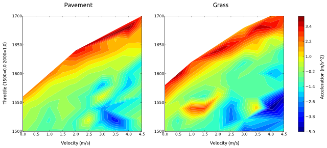
My theory was that for a given terrain, speed, and throttle, the car would exhibit a particular amount of deceleration or acceleration. This assumes that the motor controller is stateless, but otherwise encompasses a range of possible motor controller implementations. At each instant in the data file, I measured the instantaneous acceleration by sampling the velocity some fractional time before and after. Then, I created a 2D grid defined by the possible car velocities and throttles, and for each grid cell accumulated the observed accelerations. This average acceleration for each cell was then plotted using matplotlib’s tricontour function. Below I have included a sample plot from pavement and grass driving.
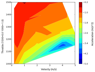
Notably, this plot has no information about regions of braking action. It turns out that it was extremely hard to actuate a suitable range of braking actions from different speeds when driving by hand. Instead, we ended up running dedicated experiments where the car started from a steady state known throttle, then commanded a constant braking throttle until the car stopped. I repeated this for a range of braking values, starting from as high a speed as I was able to do in our back lot testing area. The below plot shows those values.
The data pretty much matched the hypothesis. In fact, the acceleration could be accurately modeled using a simple electric motor model where the throttle input directly controlled the voltage applied to the motor when powering forward. A similarly simple model matched the braking behavior. These models were enough to create a velocity controller which can accelerate and decelerate much faster, while still maintaining position accuracy of velocity. However, before we were able to make it work robustly, there was one other annoyance which I’ll discuss in the next post, motor backlash.