As we gear towards higher speeds with our robomagellan entry, Savage Solder, one of the harder challenges is managing the terrain that the car drives on. In general, robomagellan competitions are held in campus or park like environments that consist of a mix of grass, pavement, wooded areas, and buildings. All of these terrain features affect how the car can navigate, and at what speeds. For instance, it shouldn’t drive into trees or buildings. In grass, the maximum speed should generally be lower than on pavement. Transition points may need an even lower speed as there could be a large bump where an area of grass ends, or where a manhole or other negative obstacle is present. Last year, we ran the car at about a maximum of 5mph, at which speed our platform can handle most all of the common event terrain features. However, as we go faster, we will want to make sure that if possible, the car stays on pavement, and avoids areas that could cause large problems.
We broke down our approach to tackle this problem into a number of discrete stages:
**Online Replanning:**First, the car will run a local A* planner over short distances in the future. Initially, this will just avoid unexpected cones, since we are already tracking all cones in the vicinity of the car.
Oracular Terrain:Next, we will hand annotate a map of one of our simulated environments, and create a synthetic “sensor” which reports the exact maximum speed in the robot’s local coordinate frame. This will feed into the local planner to keep the car on the path and at an appropriate speed.
Derive Terrain from Camera:In the final stage, we will use our camera data to estimate what the maximum speed of visible terrain elements are, likely by using a simple color classifier.
We have implemented a rough prototype of the local replanner and have had success both in simulation and in the field with it. It operates as a hybrid A* planner with a primary state space consisting of x, y, heading, and velocity. The auxiliary, non-searched, states are just the previous steering command. At each time step, the planner searches a range of steering angle adjustments, as the steering servo on our platform requires about 1.5s to move from lock to lock. In a given plan time step only a small fraction of that motion is possible. The cost metric incorporates the rate at which the steering is changed, the distance away from the global waypoint path, and the proximity to any nearby cones.
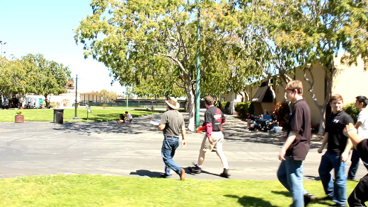
Savage Solder online replanner
In the picture above, the green vectors show the different possible vehicle positions and orientations that were considered, the black line shows the global waypoint path, and the blue line shows the best path explored so far. Each of the circles is an estimated cone (in this case there was actually only one cone, but the estimator hallucinated a few more in the vicinity).
Next, on this front, I’ll look into our efforts with an oracular terrain sensor.
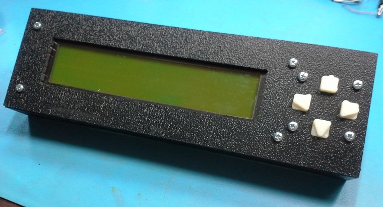
One of the minor improvements we had planned for Savage Solder, our robomagellan entry, was to build a new enclosure for our LCD. I used this as an opportunity to experiment with some new manufacturing techniques in order to make something that was both more customized and still looked relatively professional.
In our previous incarnation of Savage Solder, our laptop was generally left closed while the car was in motion to save wear and tear on its hinges. During those periods, the LCD provided information on which stage of the plan the software was in, whether it was homing on a cone, and other auxiliary pieces of status. Watching the display as the car was moving added a lot of value over just looking at the results after the fact, as we had a lot more context.
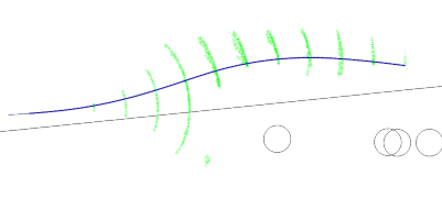
FeeCAD Model of Enclosure
My plan was to build an enclosure box using custom machined faces of ABS plastic, similar to Gary Chemelec’s approach documented at http://chemelec.com/Projects/Boxes/Boxes.htm. Basically, you cut sheets of ABS plastic into the correct dimensions for each edge, machine any holes for panel mounts, and then weld the result together with a plastic solvent.
Since I have been experimenting with some 3D printing, I drew up a 3D solid model of the display and an enclosure in FreeCAD. This gave me some confidence that I would be able to get the mounting hardware lined up properly with the display, and that the box dimensions would be big enough to encompass all the resulting hardware. In addition to the raw ABS box, a sheet of clear polycarbonate is inserted in between the LCD and the ABS cutout to better protect the LCD.
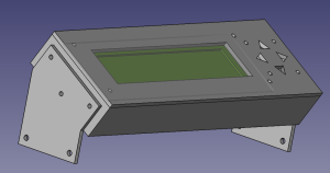
FreeCAD Model of Button
With that model, I ordered some ABS sheet from amazon, and went down to the Artisan’s Asylum to cut each side to the correct dimensions and machine the various holes. I used a jump shear to get each piece to roughly the correct dimension, then the Bridgeport mill with an Onsrud end mill bit to get each side square and to as close to the correct dimensions as I could. This portion of the process didn’t go as smoothly as I would have liked as I broke two mill bits making novice mistakes on the milling machine. I had planned on milling out the large LCD face using the mill as well, but instead of ordering a third mill bit, I just drilled a long series of holes using a standard ABS drill bit and completed the final cut and polish with a Dremel tool.
The welding process went relatively smoothly. I used an ABS glue compound that was a mixture of MEK (methyl ethyl ketone) and acetone and worked one edge at a time. The first edge was clamped to a square aluminum tube for alignment, the others self aligned against the already installed edges.
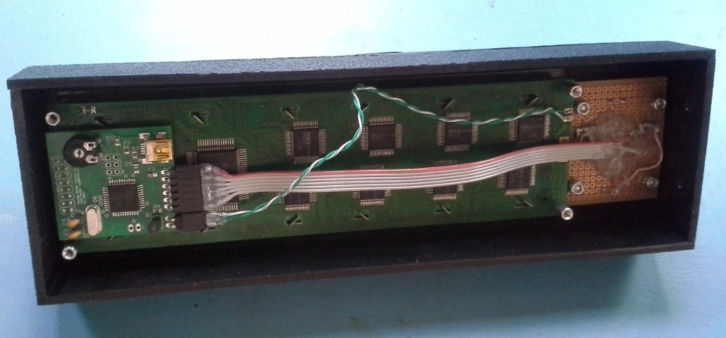
Unpopulated LCD Control Board
For the buttons on the right side of the display, I built a small backing board with a few momentary contact switches, then 3D printed a set of plastic buttons to fit into the front face holes that would be captured between the front face and the momentary contact switch. I used small bits of sandpaper to finish the face holes so that the buttons would have a snug, but freely moving fit.
The LCD itself was a 40x4 character version that Mikhail had previously developed an ATTiny hand built board to convert to RS232. The hand built board wouldn’t fit easily in the enclosure, so I drew up a PCB based on an ATMega32U4 which would go straight to USB, take up a bit less space, and use up some of the old parts I have lying around the lab. There were only two minor problems bringing up that board when it arrived. First, I did not realize that PORTF on the ATMega32U4 comes from the factory reserved for JTAG, where I was expecting it to be immediately available for GPIO. You can select the mode either with a boot fuse, or by configuring appropriate registers in software. Second, the LCD didn’t have any documentation, and at the time I didn’t have the source code to the original controller, so I mostly guessed at the HD44780 pinout, with the assumption that I could change things around in firmware later if things proved wrong. My guesses were actually mostly correct, but I got the ordering of the HD44780’s 4 data pins mixed up, so some bit re-arranging was required in the AVR that I hadn’t intended.
The final enclosure is pictured below, hopefully soon I will have pictures of it mounted on Savage Solder itself!
In the last post on my autonomous racing helicopter I managed to get the OV9650 camera communicating in a most basic way over the I2C bus. In order to actually capture images from it, the next step is to get a linux kernel driver going which can connect up the DM3730’s ISP (Image Signal Processor) hardware and route the resulting data into user space.
After some preliminary investigation, I found the first major problem. In the linux tree as of 3.6, there is a convenient abstraction in the video4linux2 (V4L2) universe for system on chips where the video device as a whole can represent the entire video capture chain, but each new “sensor” only needs a subdevice created for it. And there are in fact a lot of sensors already existing in the mainline kernel tree, including one for the very related OV9640 camera sensor. The downside however, is that there are two competing frameworks that sensor drivers can be written to, the “soc-camera” framework and the raw video4linux2 subdevice API. Sensors written for these two frameworks are incompatible, and from what I’ve seen, each platform supports only one of the frameworks. Of course, the omap3 platform which is used in the DM3730 only supports the video4linux2 API whereas all the similar sensors are written for the “soc-camera” framework!
Laurent Pinchart, a V4L2 developer has been working on this effort some, but I had a hard time locating a canonical description of the current state of affairs. Possibly the closest thing to a state of the soc-camera/v4l2 subdev universe can be found in this mailing list post:
Subject: Re: hacking MT9P031 for i.mx
From: Laurent Pinchart <laurent.pinchart@xxxxxxxxxxxxxxxx>
Date: Fri, 12 Oct 2012 15:11:09 +0200

...

soc-camera already uses v4l2_subdev, but requires soc-camera specific support
in the sensor drivers. I've started working on a fix for that some time ago,
some cleanup patches have reached mainline but I haven't been able to complete
the work yet due to lack of time.

--
Regards,

Laurent Pinchart
Since I don’t have a lot of need to upstream this work, I took the easy route and started with an existing v4l2 subdevice sensor, specifically the mt9v034 which is in the ISEE git repository. I copied it and replaced the guts with the ov9640 “soc-camera” driver from the mainline kernel. After a number of iterations I was able to get a driver that compiled, and appeared to operate the chip.
To test, I have been using Laurent Pinchart’s media-ctl and yavta tools. The media controller framework provides a general way to configure the image pipelines on system on chips. With it, you can configure whether the sensor output flows through the preview engine or the scaler and in what order if any. yavta is just a simple command line tool to set and query V4L2 controls and do simple frame capture.
One of the first images with correct coloring is below. Single frame capture out of the box was recognizable, but the quality was pretty poor. Also, as more frames were captured, the images became more and more washed out, with all the pixel values approaching the same bright gray color. That problem I will tackle in a later post.
I am now far far down the rabbit hole of trying to validate a camera for the low altitude altimetry of my prototype autonomous racing helicopter. In the last post I got to the point where I could build system images for my IGEP COM Module that included patches on top of the ISEE 3.6 linux kernel. The next step was to use that ability to turn on the clock at the TI DM3730’s external camera port.
First, what is the path by which a normal camera driver turns on the clock on the IGEP? To discover this, I traced backwards from the board expansion file for the CAMR0010 produced by ISEE, just because it was the easiest place with a thread to start grasping. In the board expansion file, “exp-camr0010.c”, a function is defined specifically to configure the ISP’s (Image Signal Processor) clock:
However, in the absence of a full camera driver, it was not entirely clear how to get a hold of a “struct isp_device*” that you could use to configure the clock. To understand more, I traced the many layers this function is passed down through before leaving the board expansion source file:
mt9v034_platform_data: This structure was defined by ISEE and is exposed from the new mt9v034 driver.
i2c_board_info: The mt9v034_platform_data structure is passed into this one as the “.platform_data” member.
isp_subdev_i2c_board_info:The i2c_board_info structure is passed as the “.board_info” member of this structure.
isp_v4l2_subdevs_group_camera_subdevs: The board_info structure is passed in here as the “.subdevs” member.
isp_platform_data: The camera_subdevs member is passed in here as the “.subdevs” member.
omap3_init_camera: Finally, the platform_data structure is passed in here.
Eventually, this clock setting callback is stashed inside the mt9v034 driver where it is invoked in a couple of places. Yikes! I tried to backtrack this route to get an isp_device, but had no luck. What did end up working was grabbing the driver, then device by name: (error checking and the “match any” function omitted for clarity)
Then, I exposed this functionality through a simple debugfs entry that appears in /sys/kernel/debug/arr_debug/xclka_freq (when debugfs is mounted of course). Then I was able to write frequencies from the command line and get the external clock to run at any frequency I chose. Yay!
There was one final piece to the puzzle before I could claim the camera was functional. The OV9650, while electrically compatible with I2C, is not an SMBus device. The standard linux command line tools, i2cget and friends were not able to drive the camera in a useful way. To get over the final hurdle, I wrote a simple user-space C program which opens “/dev/i2c-3”, sets the slave address using the I2C_SLAVE ioctl, and then uses the bare “read” and “write” API to send and receive bytes of data. With this, I was able to extract the product identifier from the chip of 0x9652! I guess it is likely a subsequent revision of the 9650.