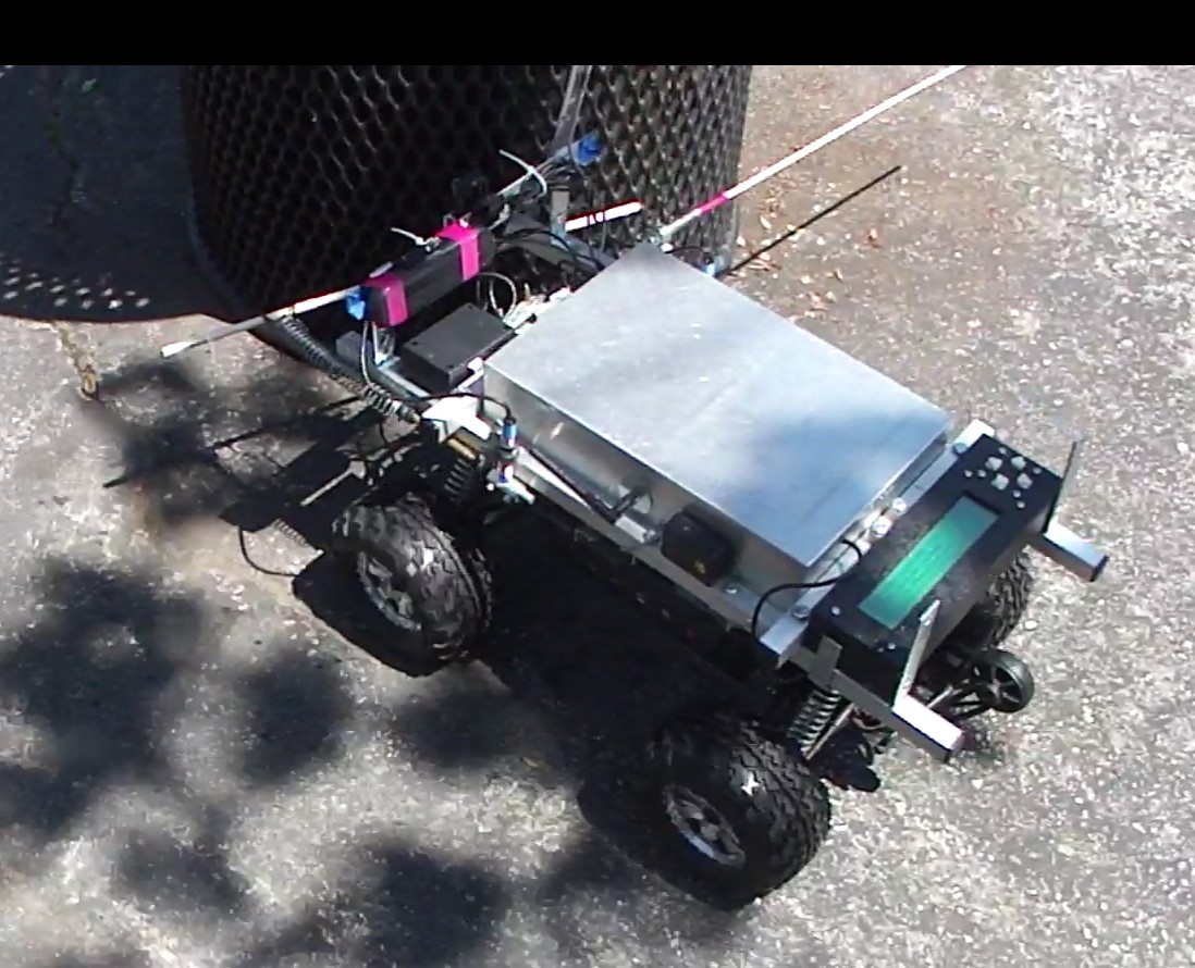
Savage Solder: Localization Part 2
In part 1 I looked at the reasons why we use a state estimation filter for Savage Solder’s localization system and what the options were. This time, I’ll look at the specific measurements we take and the resulting states that we estimate along with some implementation details.
Measurements
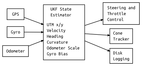
Our localization system uses the following measurements:
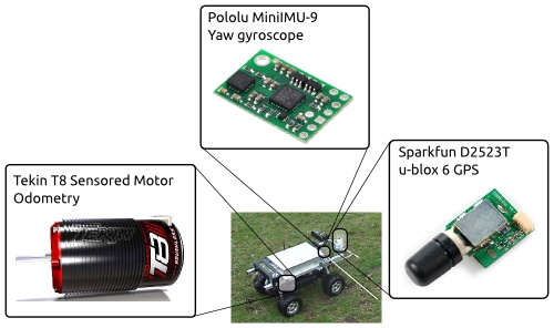
- GPS: UTM (Universal Transverse Mercator) referenced position from a u-blox 6 GPS sampled at 4Hz
- Gyroscope: We use the yaw rate from a Pololu MiniIMU-9 sampled at 50Hz
- Odometer: We feed the sensors from our sensored brushless motor to an AVR microcontroller and count motor steps to measure odometry at 50Hz. This is not perfect, (for example, it suffers from backlash), but works reasonably well.
Each of these measurements is integrated into the state estimation filter at their natural rate. The filter only emits a solution on each IMU update, just to reduce the variability in the rest of the system.
Savage Solder Localization Sensors
Estimated States
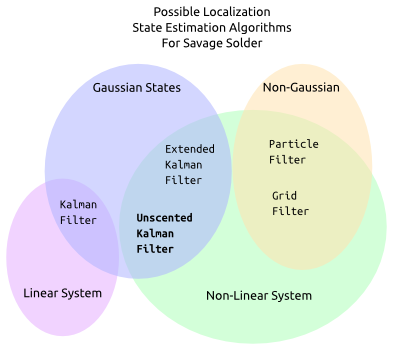
The Unscented Kalman Filter (UKF) estimates the following system states:
- X/Y Position: The position is estimated in a UTM coordinate reference. We nominally estimate where a position under the center of the rear axle is, but the car is small enough that lever arms don’t really come into consideration.
- Velocity Velocity is estimated assuming no lateral slip.
- Heading: We assume that the car is always perfectly flat, and that the only orientation degree of freedom which matters is heading.
- Curvature: We assume that the car moves in a car like way, and thus, given no change in steering input, it will drive in a circle.
- Odometer Scale Factor: The only error term we estimate for the odometer is a scale factor. This is largely determined by errors in the diameter of the tires, but also is affected by the texture of the terrain that is being traversed.
- Gyroscope Bias: Gyroscopes have many error factors which can be modeled. For our purposes, since we have accurate GPS most of the time, we get away with only estimating the bias of the gyroscope.
Constant Selection and Heuristics
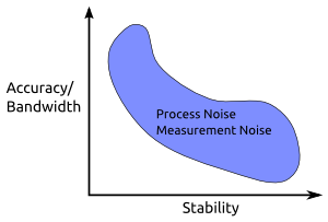
Kalman Filter Tuning Tradeoffs
When designing a state estimation filter, there are a lot of constants that need to be selected. For Kalman filters, you need an initial covariance and process noise for all estimated states, and measurement noise for all dimensions of the measured values. By choosing a specific selection of constants, you can trade off between the bandwidth (performance or accuracy) of the filter, and its stability. Generally, if you make the filter more accurate, you increase the risk that the filter will become unstable if the system model or measurement models do not accurately track the real world.
For Savage Solder, we used a largely ad-hoc approach, with no rigorous backing for our constant selection. We picked process noises that roughly corresponded to the amount of system error we expected to see, and did the same with measurement noises. One exception was GPS measurement error. Since we are using a naive total state filter, and GPS measurements from cheap receivers are highly time correlated (because of their own internal estimation filters), there are a number of other factors to consider. If the GPS measurement is set too high in this formulation, heading cannot be estimated accurately. If it is set too low, the global position will jump around a lot with every GPS update. In no case is the filter’s assumption, that of a measurement corrupted purely by white noise, satisfied, so measurements noises that are too low also run the risk of filter divergence. We just picked a happy medium that tends to work well in our simulations and practice.
There are also a fair number of heuristics included. For instance, if we know the car is stopped from the odometer, we artificially fix the heading and curvature estimates and covariances. At least when it is driving under its own power, Savage Solder rarely rotates in place. Without holding these fixed, noise in the GPS and gyroscope can cause the estimated heading to drift with no bounds and the heading uncertainty to grow arbitrarily large.
Global and Local Coordinate System
As I mentioned early in part 1, different subsystems in Savage Solder have differing requirements for the state estimates they consume. Some, like global driving, want the estimate to be close to the globally correct position so that the car can drive close to a pre-surveyed path. Others, like cone tracking, would much rather have a locally consistent frame of reference that is divorced from global coordinates entirely.
We solve this by deriving a separate local coordinate estimate from the global estimate emitted by the UKF. This local estimate always starts at position 0, 0 with a heading of 0. At each time step, the velocity, heading, and curvature of the global solution are integrated forward. This results in an estimate which is by definition smooth, yet still is relatively accurate over short distances, as the velocity and heading inputs have full access to the sensor suite of the car.
Coming Up…
In the next, and final installment, I’ll look at some techniques we are, or want to be exploring to improve the localization solution on Savage Solder.