New Project: Autonomous Racing Rotorcraft
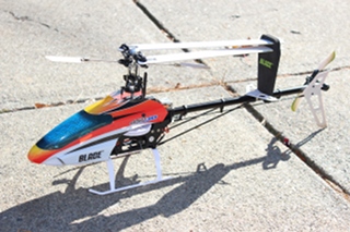 For the last 6 years I have ever so slowly been learning how to fly medium sized RC helicopters outdoors, in an attempt to become a good enough pilot that I could roboticize one. About a year ago I upgraded to a Blade 450, which let me practice outdoors in a much wider variety of weather conditions and provided for a feasible amount of payload. My proficiency is now good enough that I’ve started work on the control and navigation design with the medium term goal of entering it in autonomous racing competitions, such as Sparkfun’s AVC.
At the top end, this helicopter can lift around 100g, which while tight, should be completely doable with 2012 componentry. A rough outline of the components I have in mind now is:
- Computer - IGEP COM Module: A gumstix clone out of Spain, they are slightly smaller, slightly more powerful, and can nominally be powered and operated over USB with no baseboards required. (Although I’ve so far found that heat issues pretty much require a baseboard or other heatsink of some kind be used.)
- GPS -Sparkfun GS407: We had reasonably good luck with the u-blox 6 chipset on Savage Solder. It doesn’t have great precision, and has no way to bypass the internal EKF, but at least lets you configure it somewhat.
- IMU - Currently I’m planning on using the same chips as in the Pololu MinIMU-9 v2 just because I’ve worked with it on Savage Solder, the drift performance is reasonable, and the combined electronics only add a couple of grams.
- Altimeter - My hope is to use a structured light solution where a small camera-phone camera module looks down coupled with a laser pointer offset by some amount. The laser pointer will alternate one frame to the next to increase the signal to noise ratio. Then, the position of the pointer in the camera’s field of view should give a relatively accurate altimeter at ranges between 1 and 10m. Higher than that and I am figuring GPS will be good enough to keep it far from the ground.
- Servo Control and Failsafe - To develop the autonomous system with a minimum of crashes, it will need the ability to be controlled both by a human and by the computer, with an emergency fallback to human control. Also, for simulation modeling purposes, I want to be able to record the human inputs made during manual flights. In order to not require hard real-time performance of the linux-based IGEP board, I will use a separate AVR controller to read, pass through, or command each of the servo channels. The Blade 450 only has a 6 channel transmitter, (throttle, pitch, roll, collective, tail, and gyro gains). In case of an upgrade later on, I’ll assume that there are 8 transmitter channels that might need to be manipulated.
I have a preliminary set of milestones laid out. While each may end up taking significant effort, it will at least let me track progress. They don’t all necessarily need to be done in order of course:
- Demo Servo Control - Demonstrate that the AVR can monitor, passthrough, and command 8 servo channels while simultaneously reading full 100Hz updates from the I2C IMU, and feeding everything back over the USB link without losing accuracy. I have a working implementation of this, which I’ll cover in a later post.
- Camera and Lens Selected - Prototype and get a camera working with the IGEP COM Module and verify that its optical properties will be sufficient for altimetry and possibly horizontal motion compensation during landing.
- Block Diagram of Daughterboard - Draw up all the major components required for the daughterboard.
- Schematic of Daughterboard - Actually capture all the connections and minor components necessary for the daughterboard.
- Layout of Daughterboard - Get the first rev of the board drawn up and manufactured.
- Board Bringup - Get the board working, re-print as required.
- Flight Data Recording and Simulator - Using the flight hardware, take data of flights and use it to build a simulation model. Currently, CRRCsim looks like it will be suitable for a dynamics and visualization platform. It’s rotorcraft support isn’t great, but with some work I believe I can get it close enough.
- Navigation Filter - Using the simulator and flight tests, create a navigation solution which can accurately localize the helicopter in 6D.
- Autonomous Forward Flight - Fly simple autonomous trajectories in fast forward flight.
- Prove out Altimeter - With manual takeoff and landing, get the altimeter to a satisfactory level of performance.
- Autonomous Takeoff and Landing - Using the altimetry when close to the ground, make controlled landings and takeoffs.
Wow, that is a long road ahead.