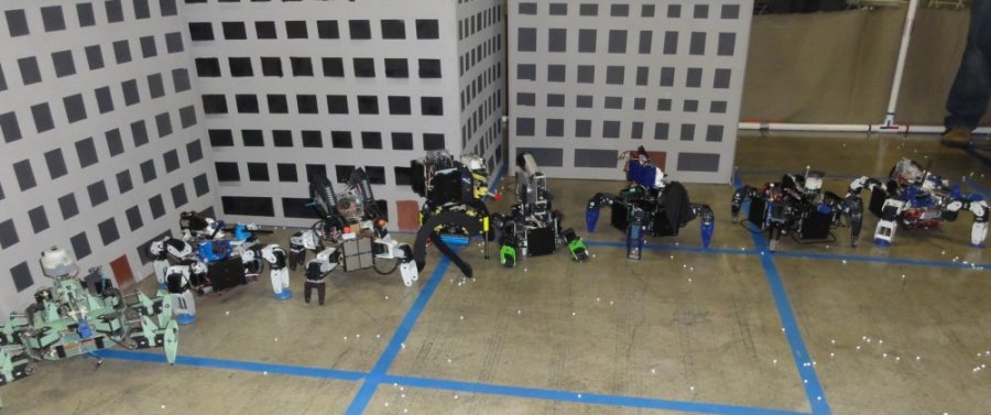
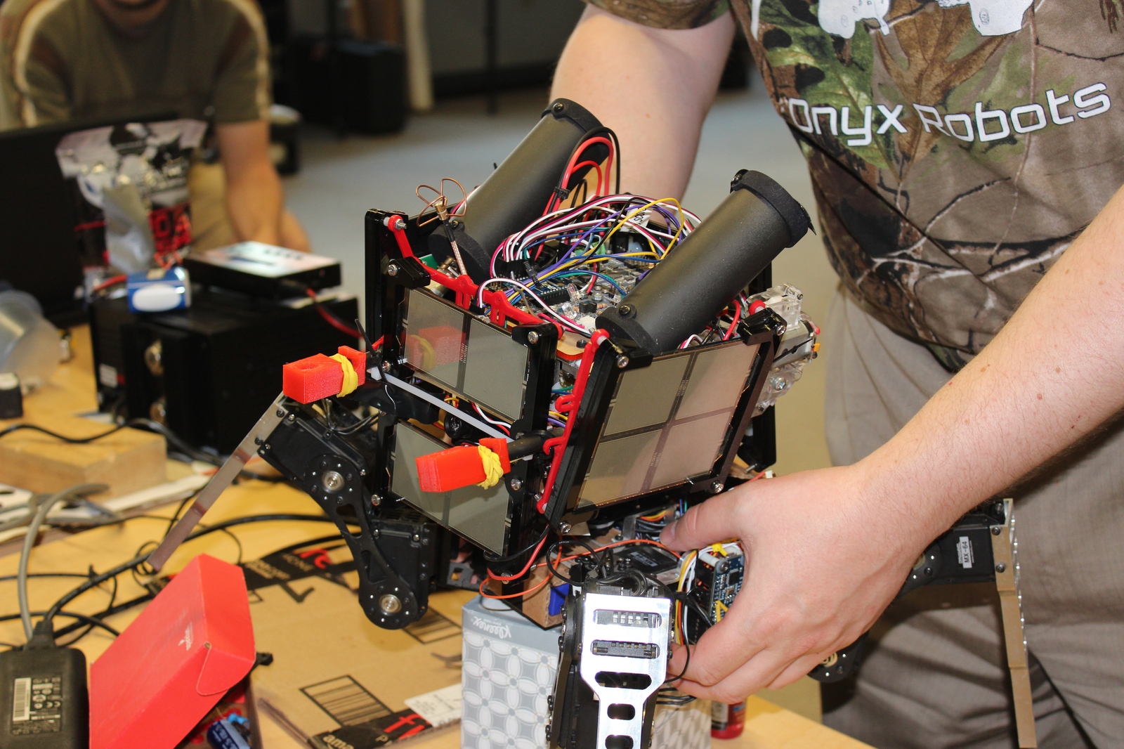
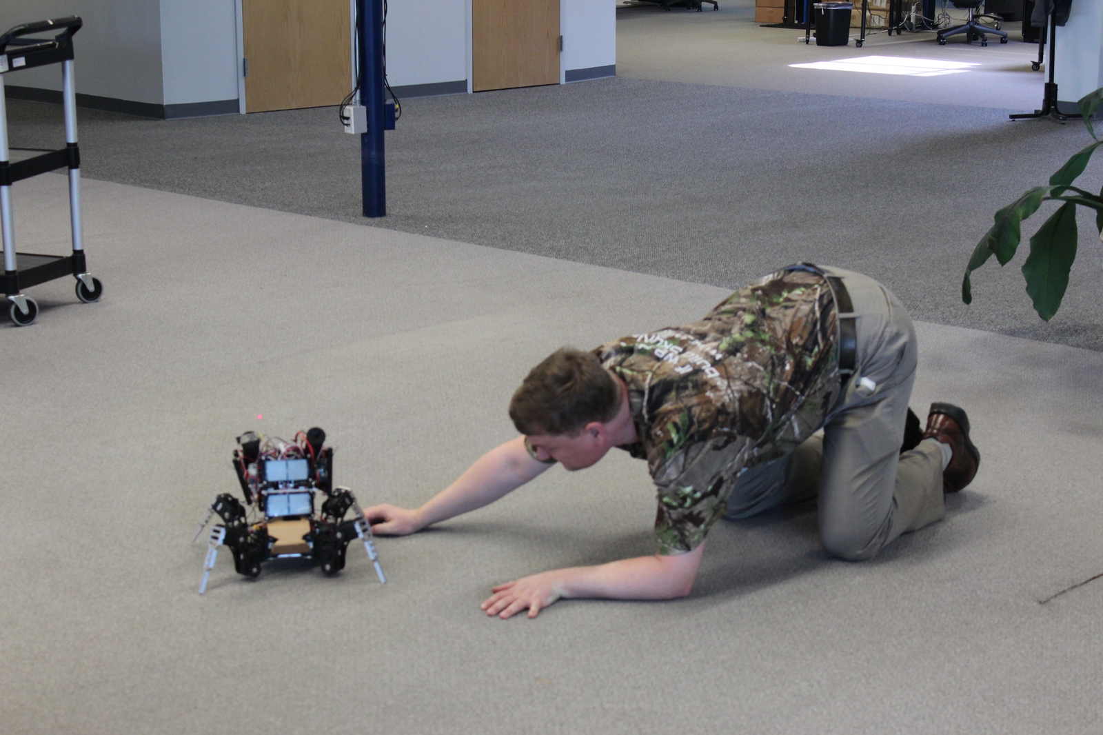
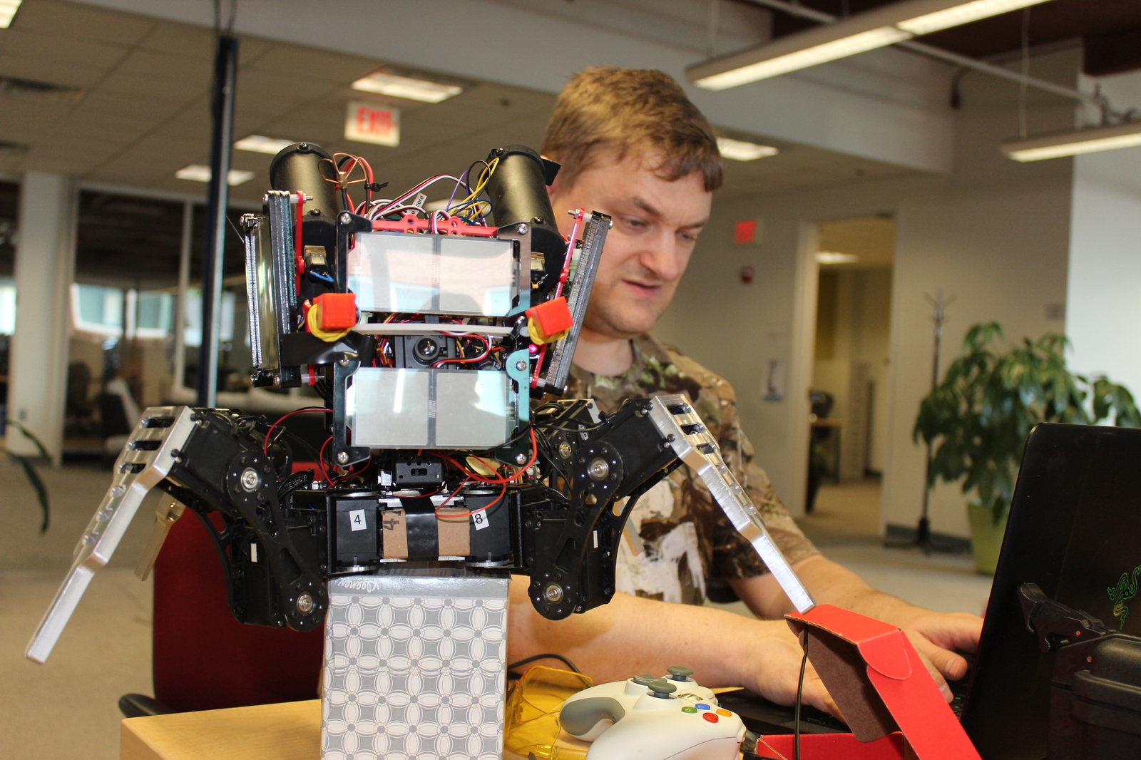
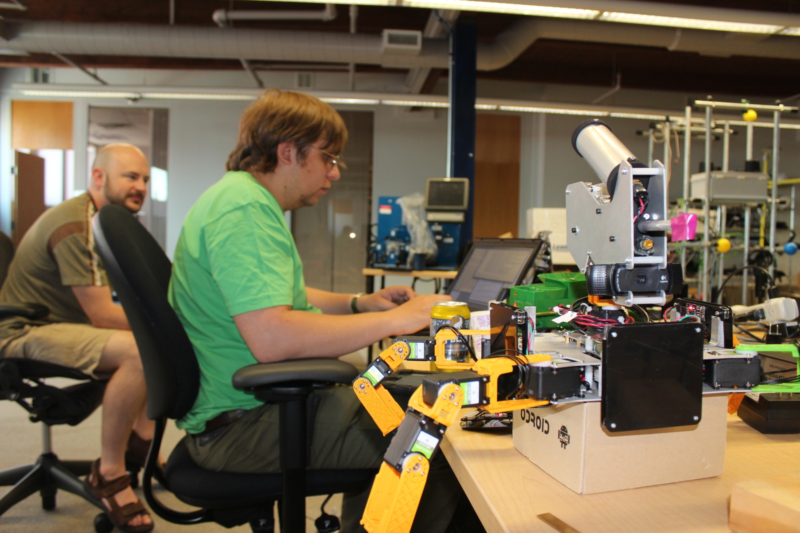
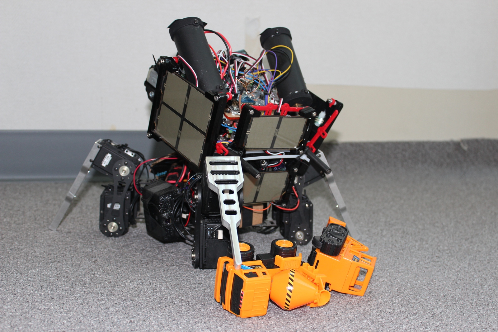
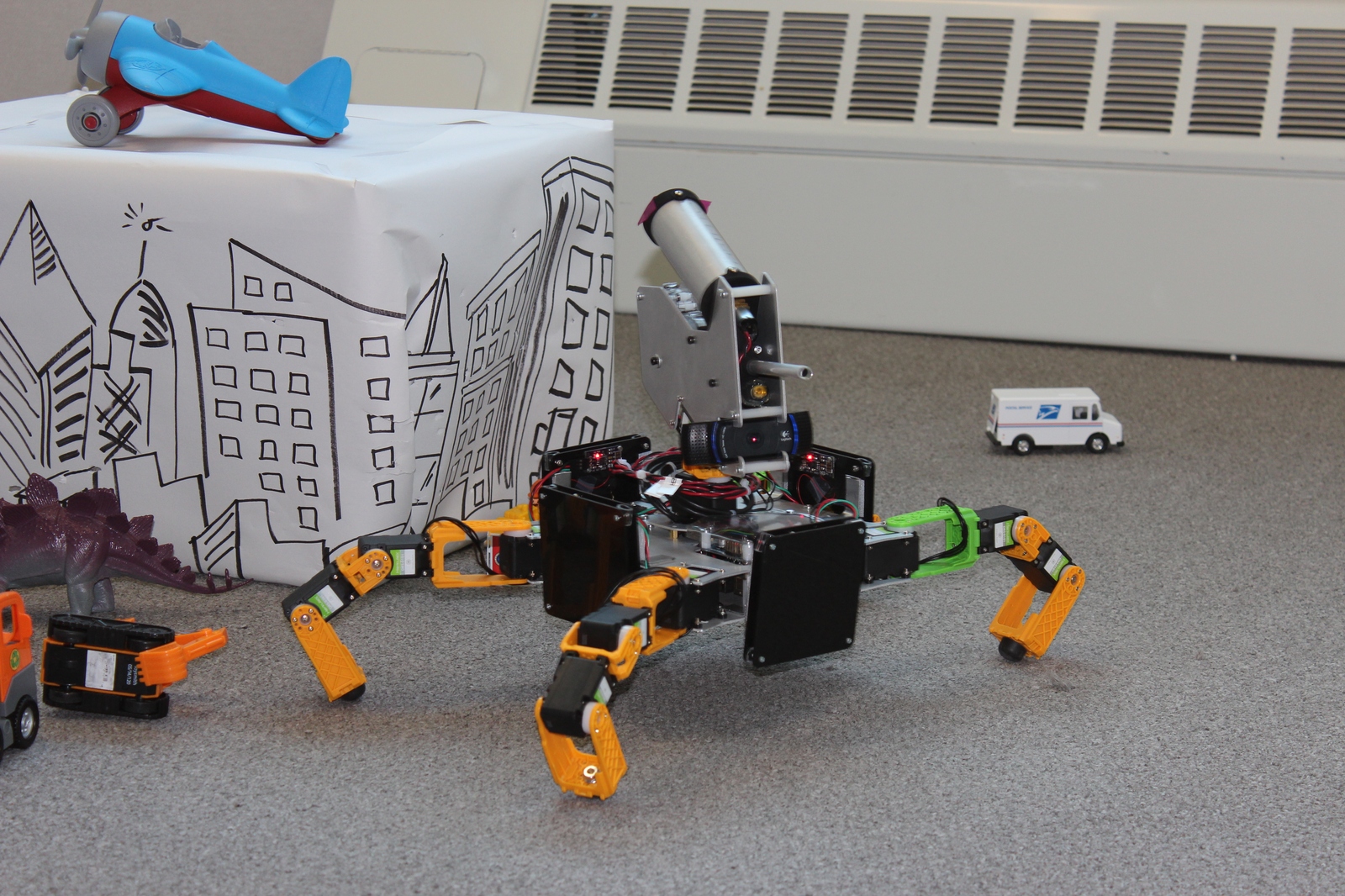
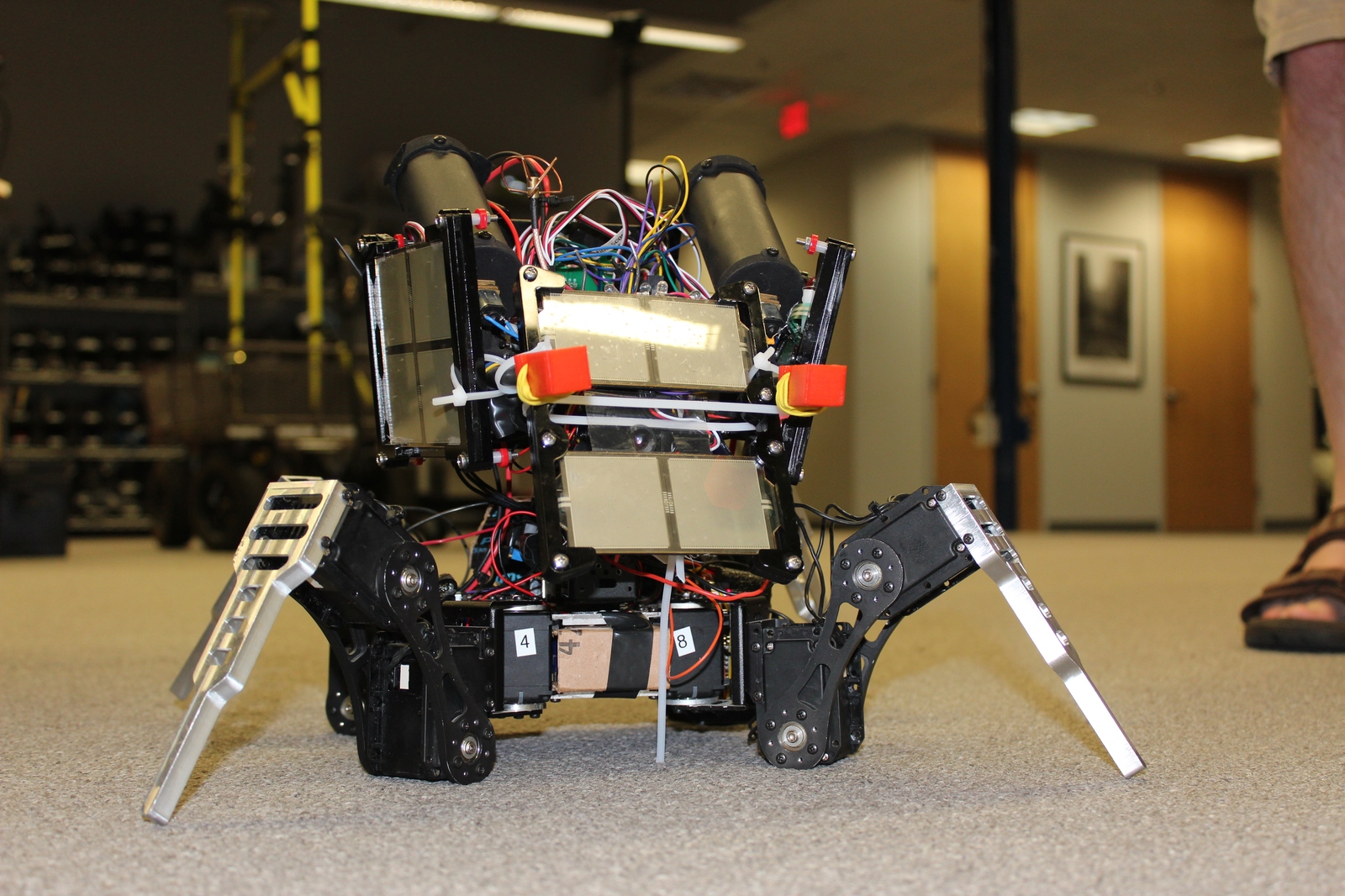
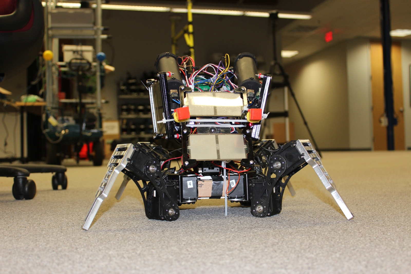
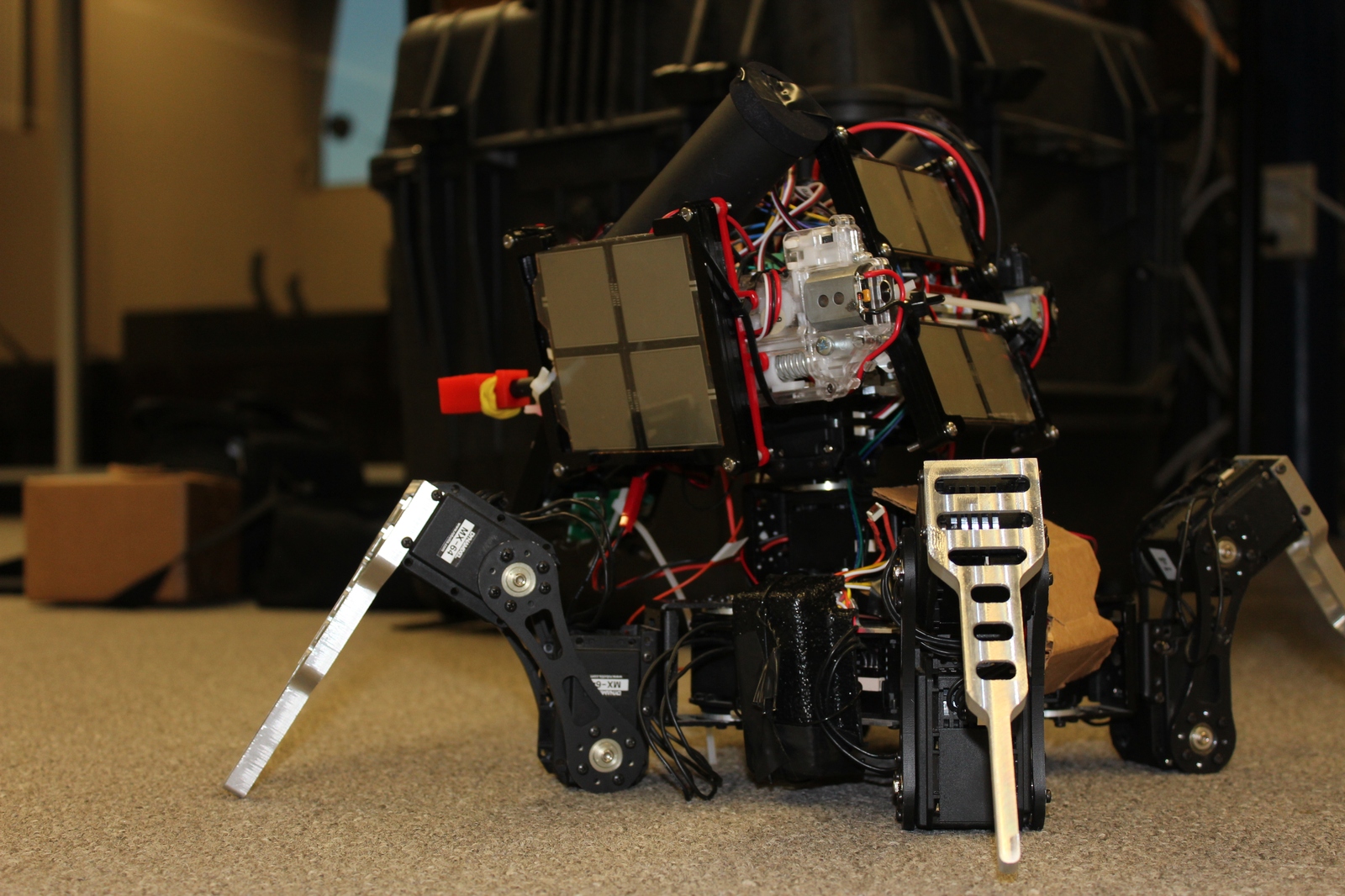
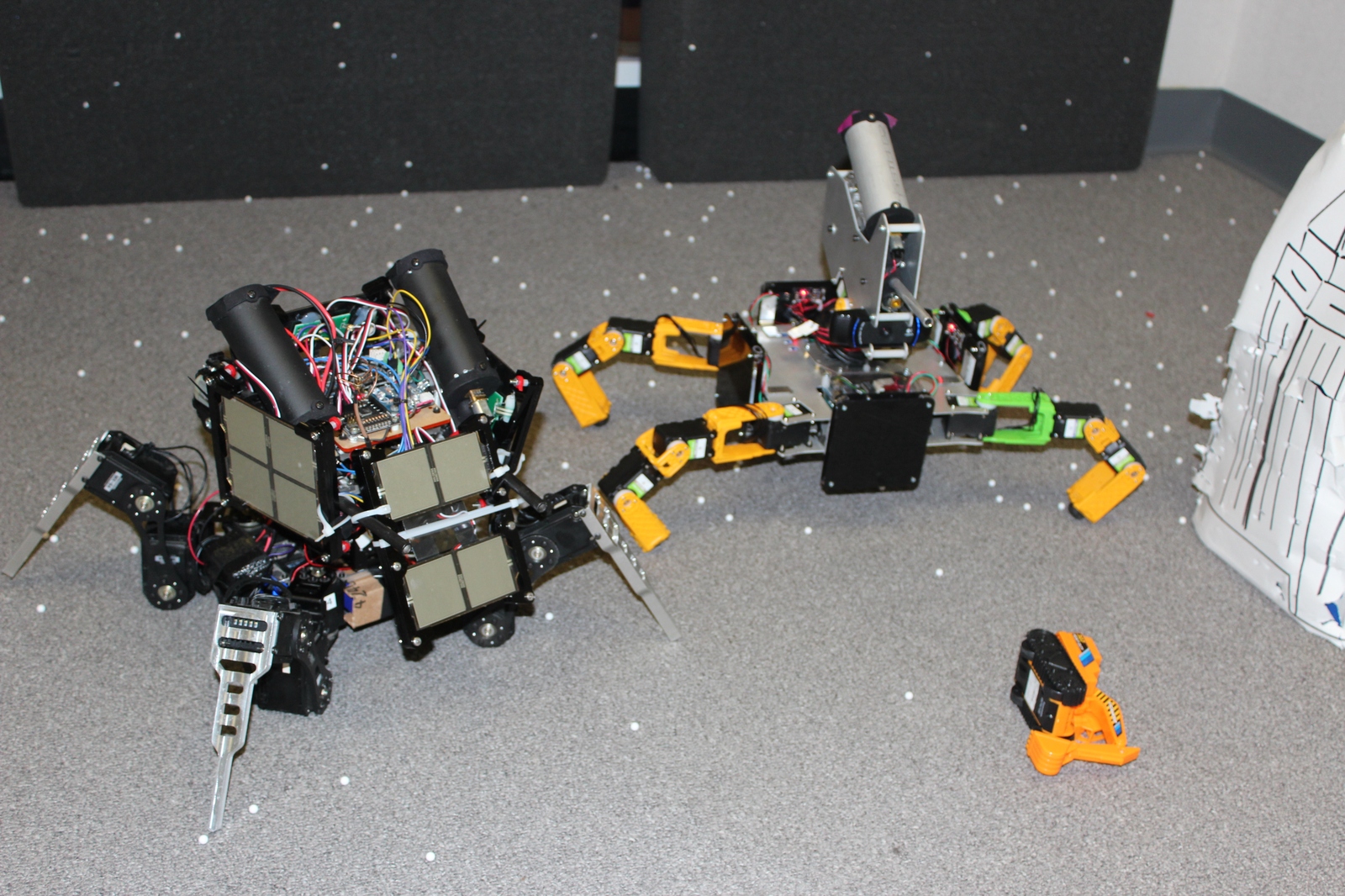
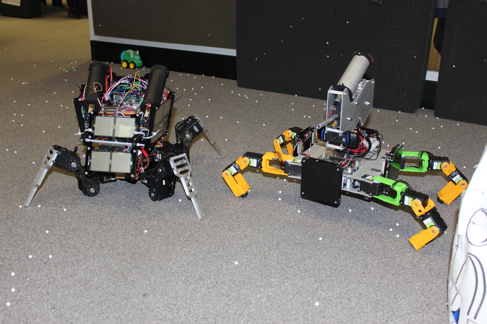
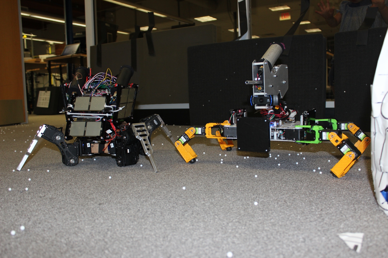
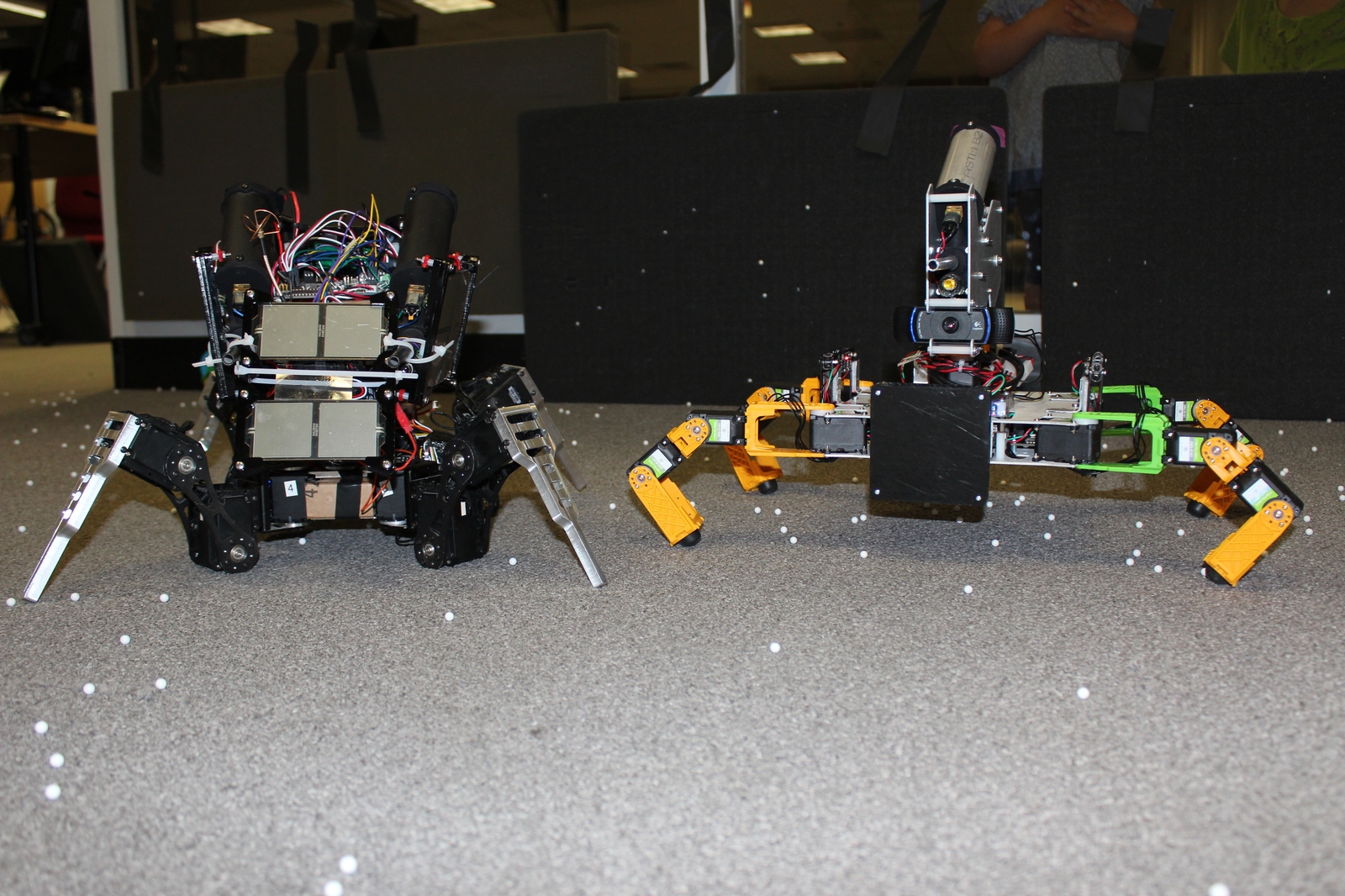
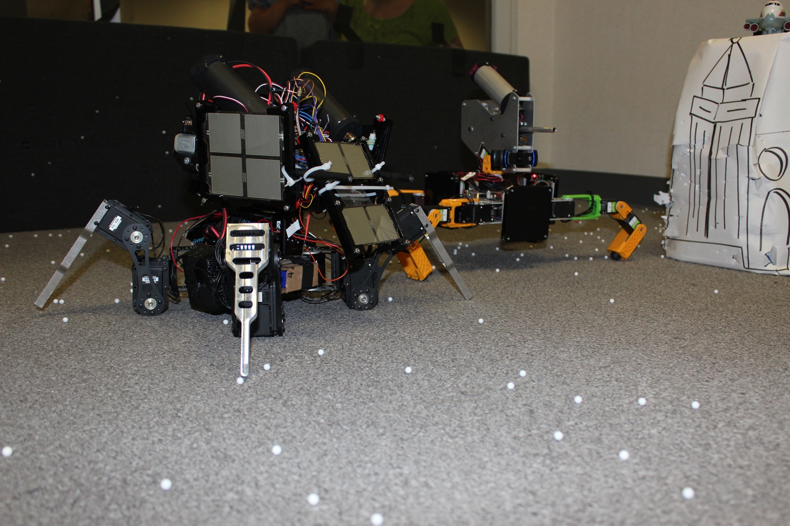
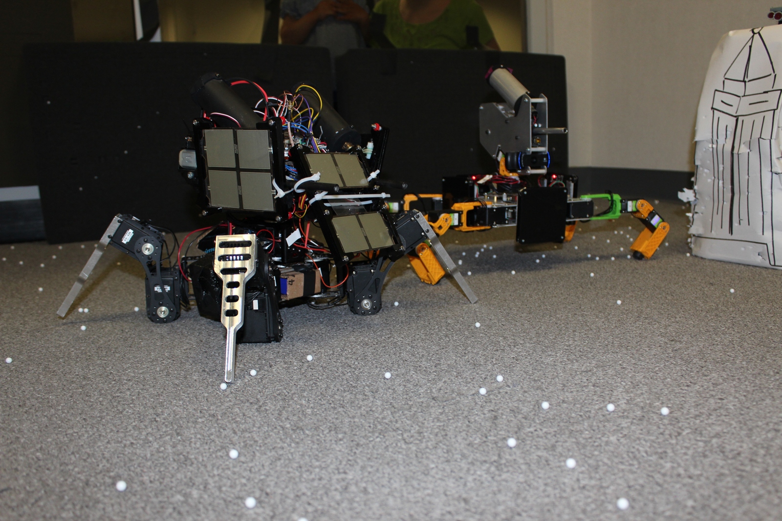
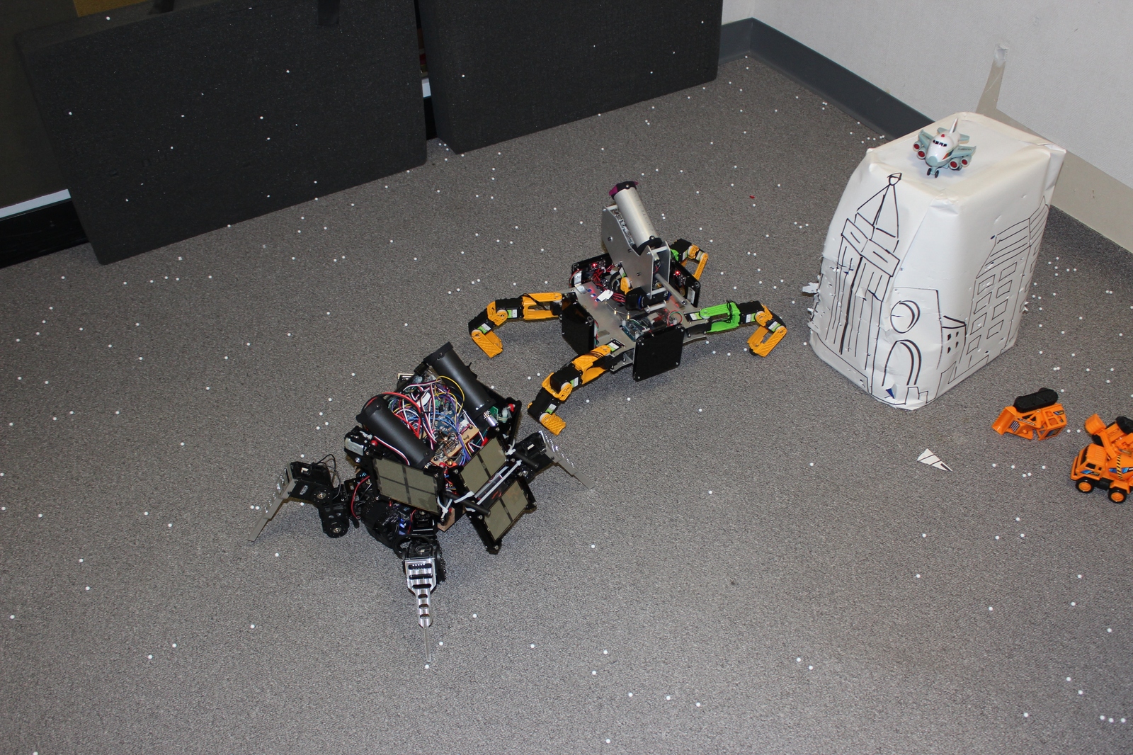
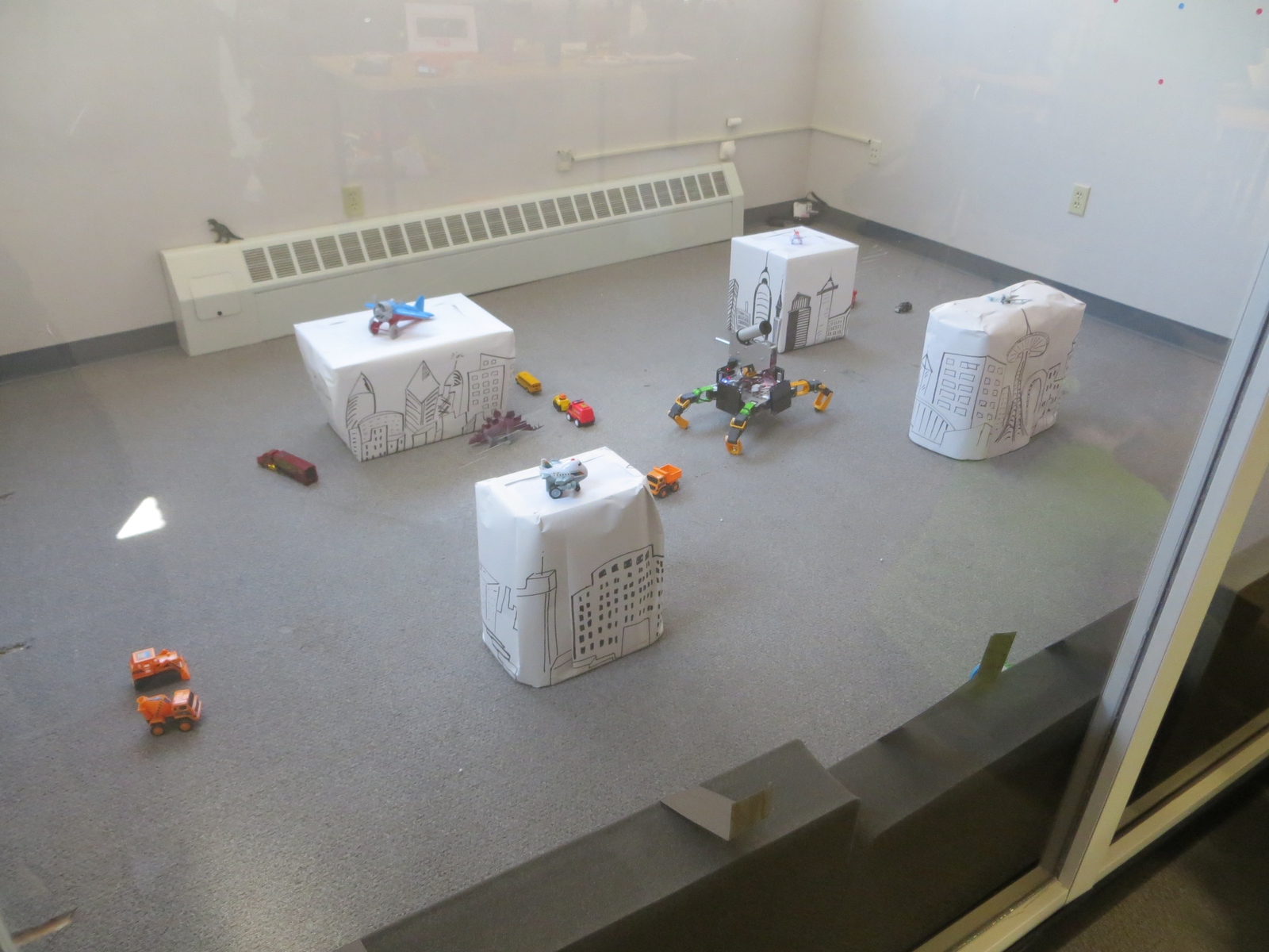
Earlier in April we took Super Mega Microbot out to California to compete in Mech Warfare during Robogames 2016. Thanks to the R-TEAM organizers who made the event happen this year. We were really excited, and the event as a whole went off really well! There were a lot of functional mechs attending, and many fights that were exciting to watch.
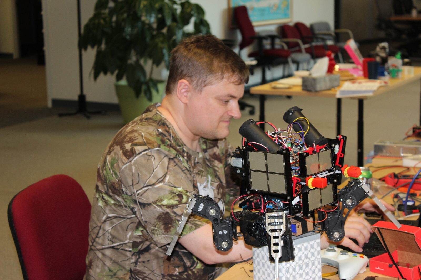
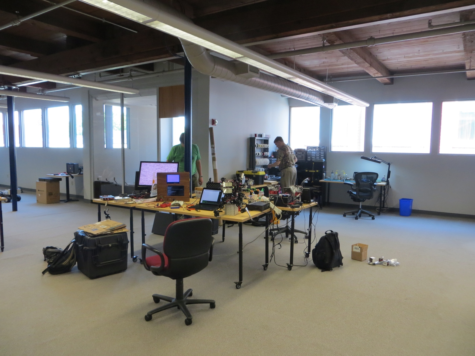
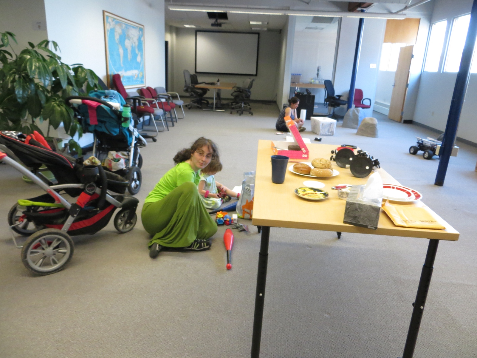
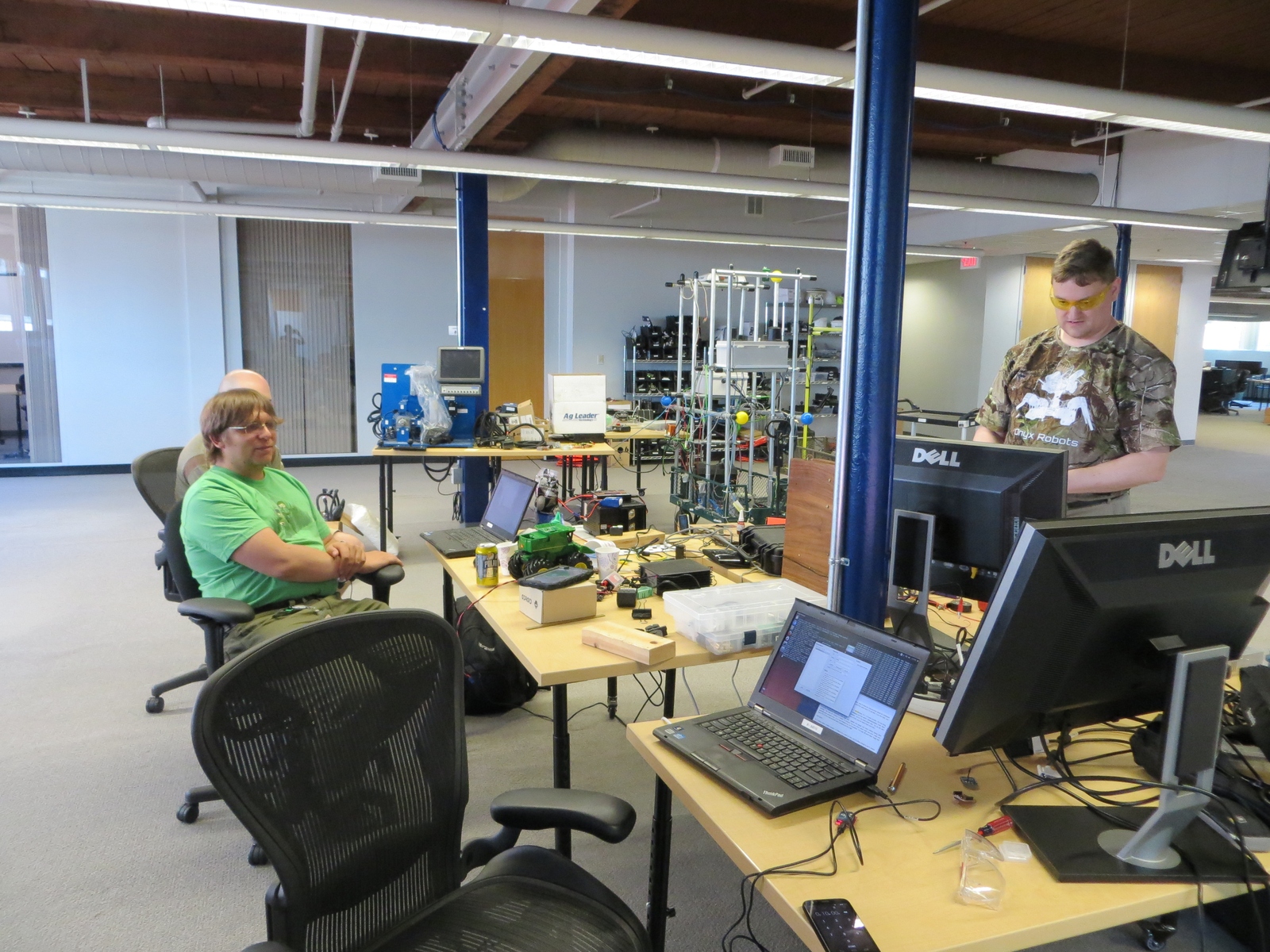
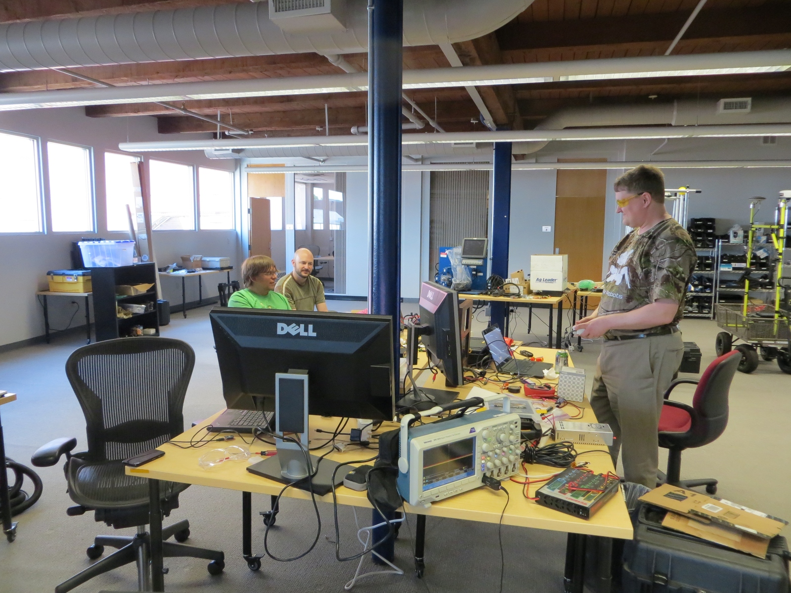
Most of the mechs which competed
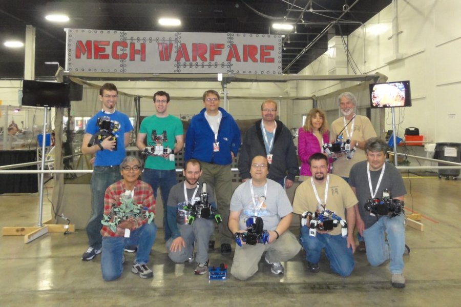
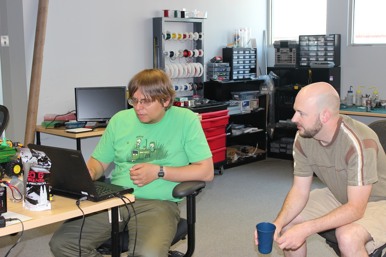
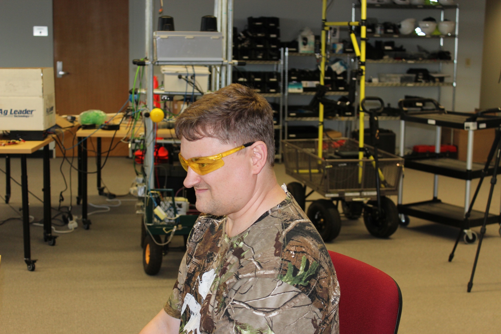
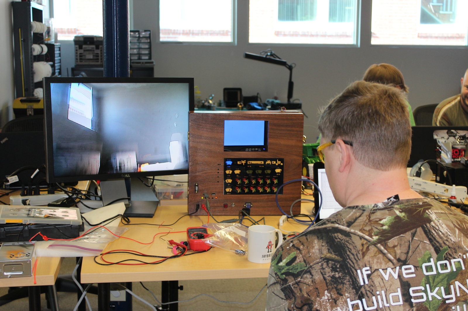
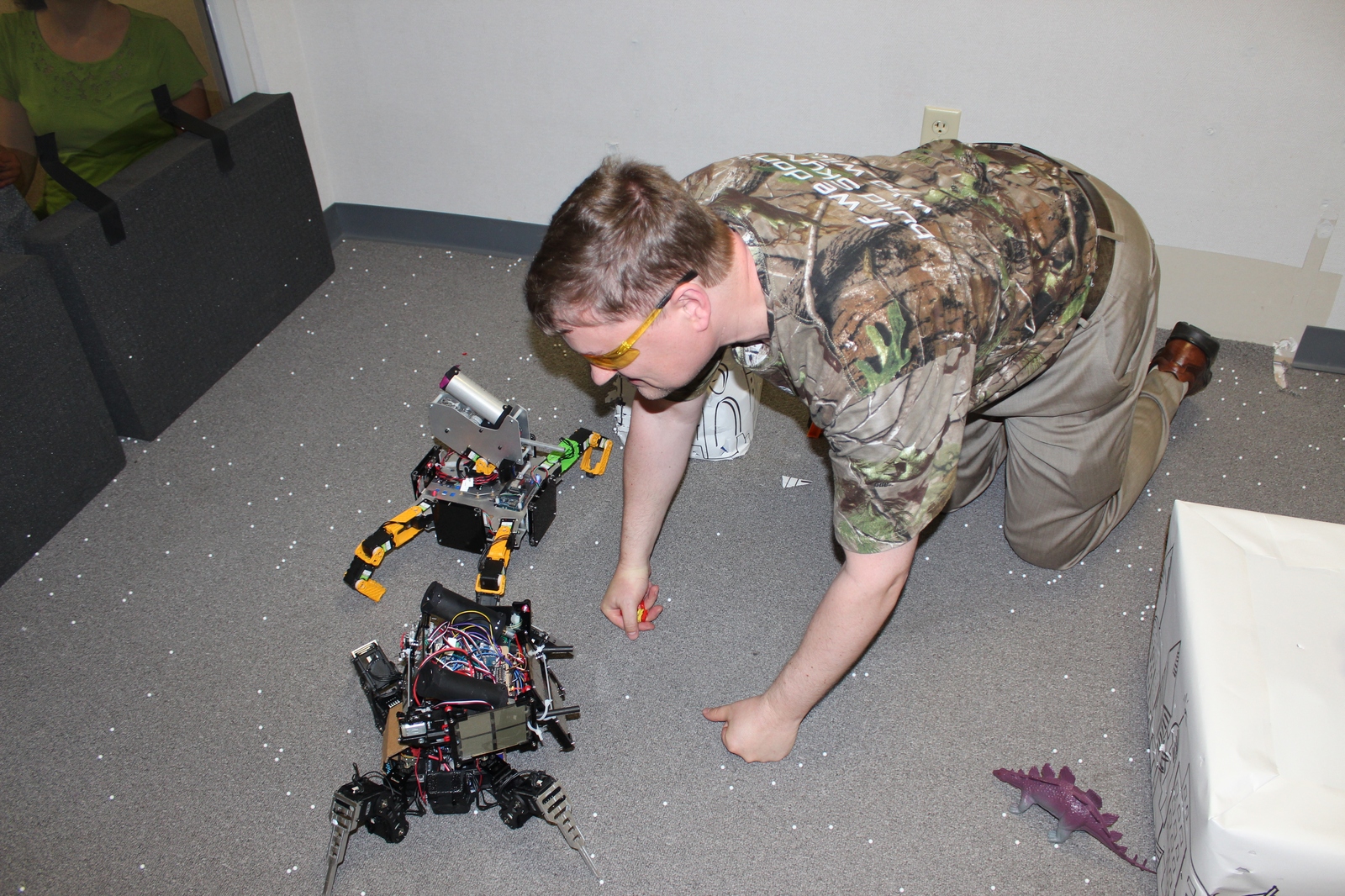
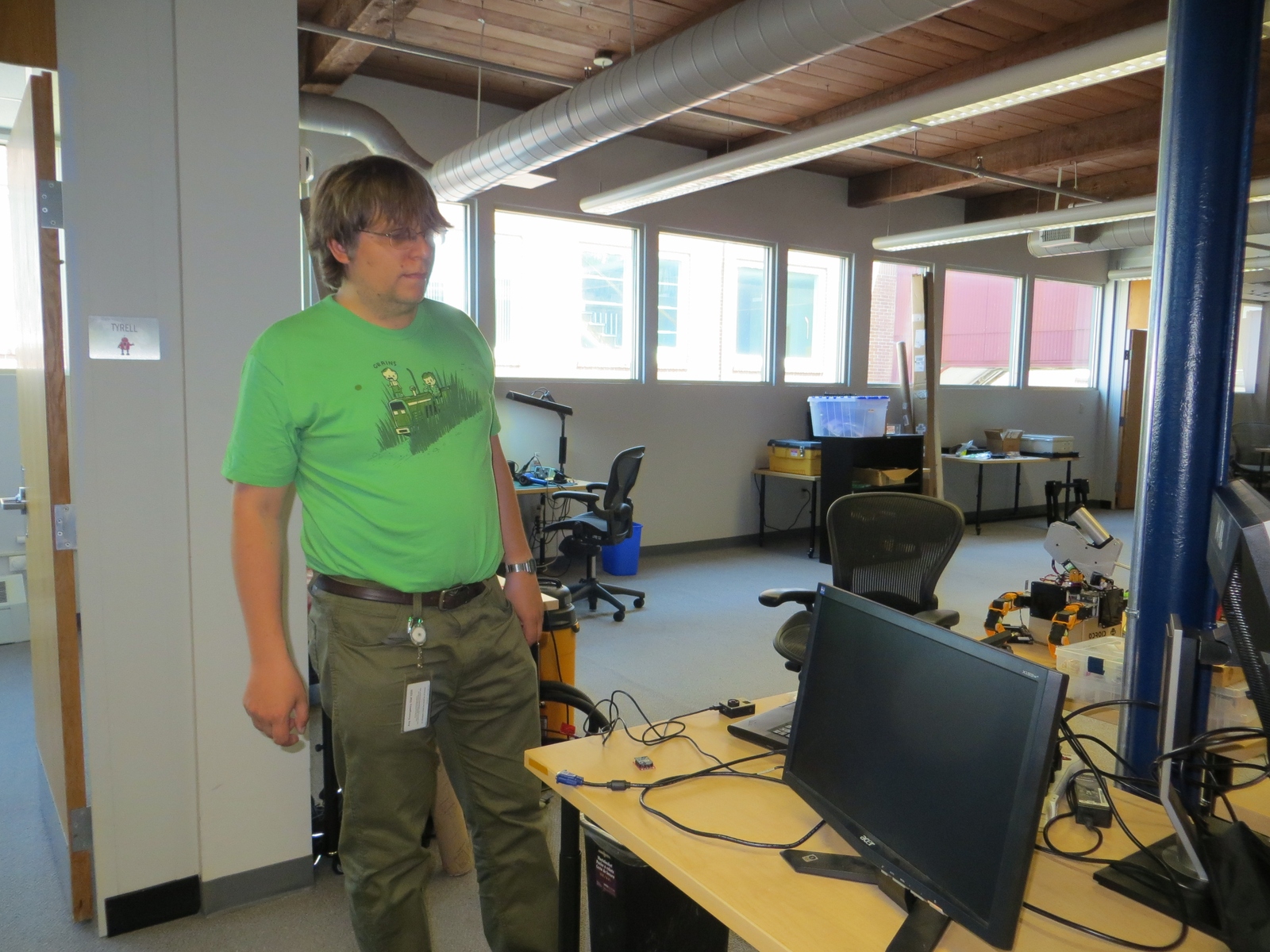
And their human operators
We managed to play 5 official matches, in the double elimination tournament, finishing in 3rd place overall. When it worked, SMMB worked really well. Our first loss was a very close battle, the score keeping system had us winning by 2 and the judges had us losing by 2. (The scoring system wasn’t super reliable, so there were human judges calling hits). Our second loss was caused when the odroid’s USB bus on SMMB stopped working mid-match, causing us to lose camera and wifi.
Takeaways
Since our last matches, we tried to improve a number of things, while some worked, not all of them are entirely successful yet:
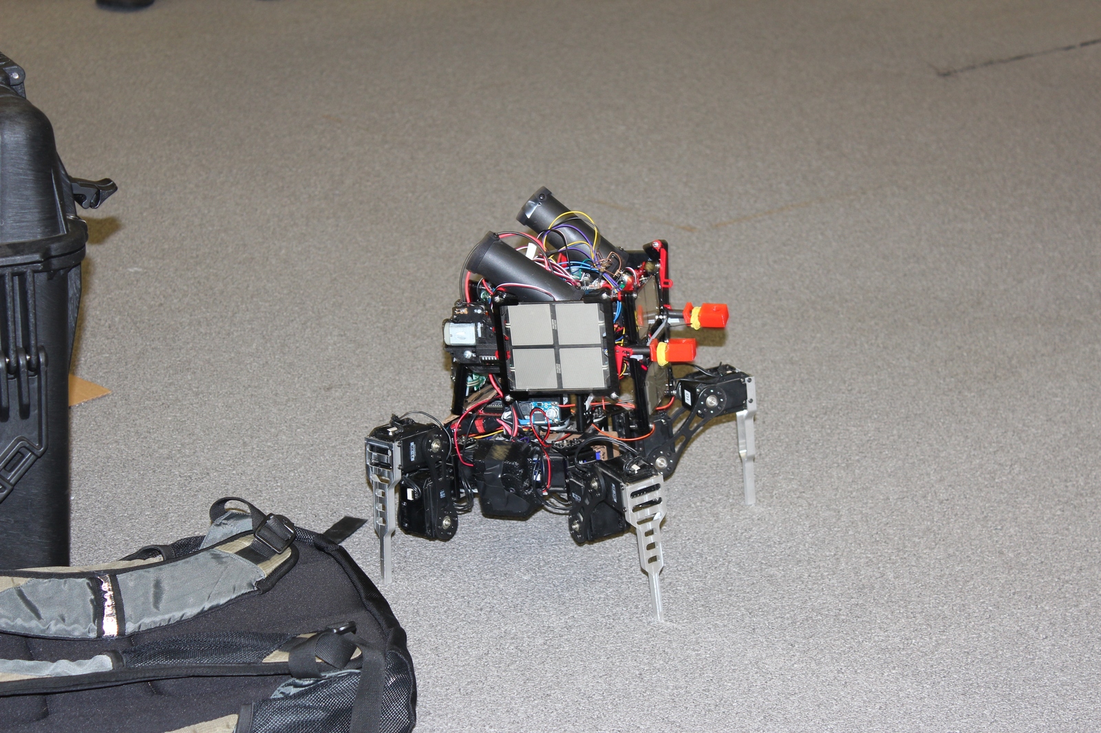
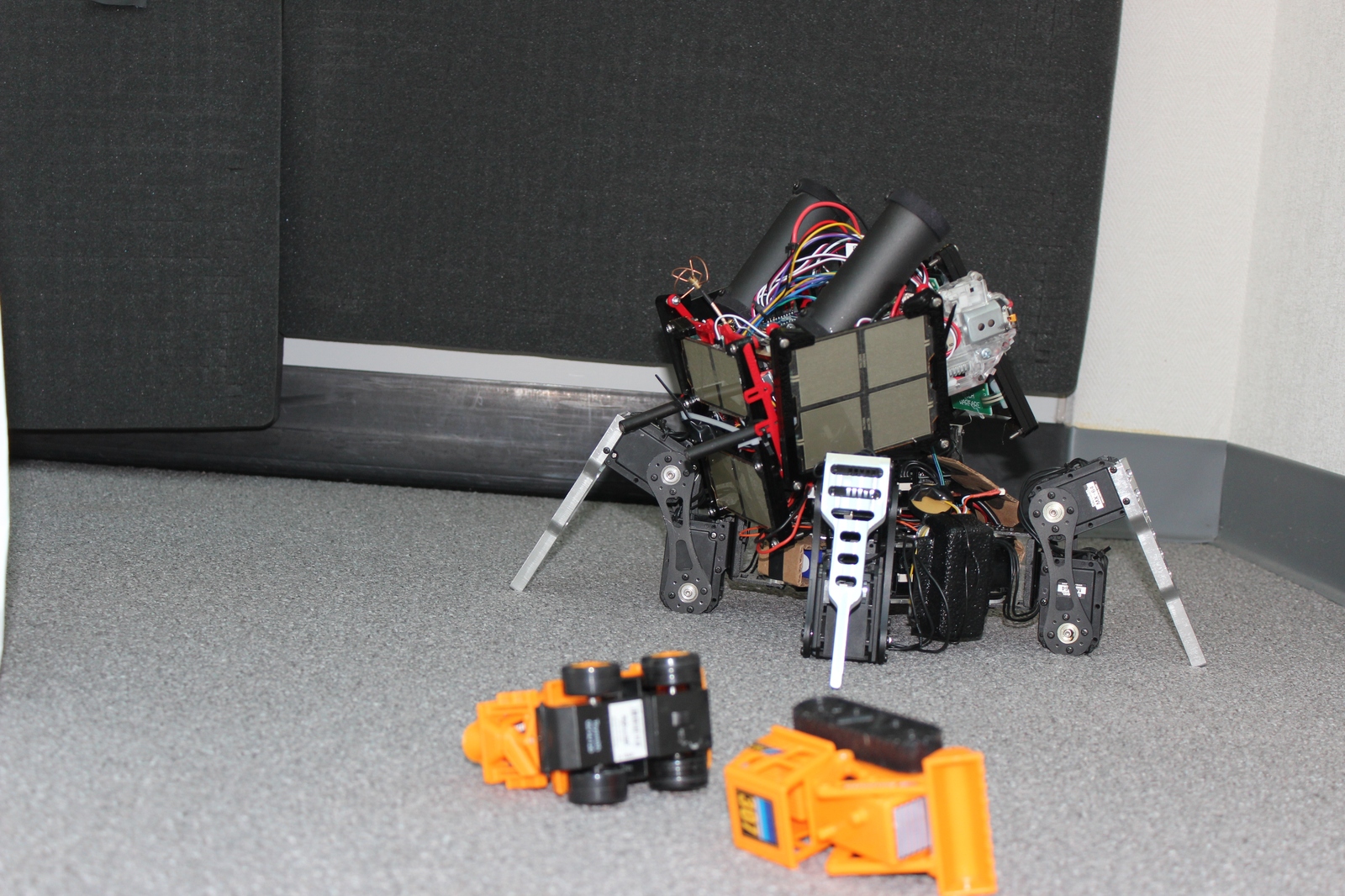
Faster walking: The new mammal chassis is about twice as fast as the old lizard one, but we didn’t get much time to make it work really well, so we were still one of the slower mechs at Robogames. Also, the shoulder bracket, even on its second revision, still had several partial failures during matches and will need to be rebuilt in metal to be strong enough.
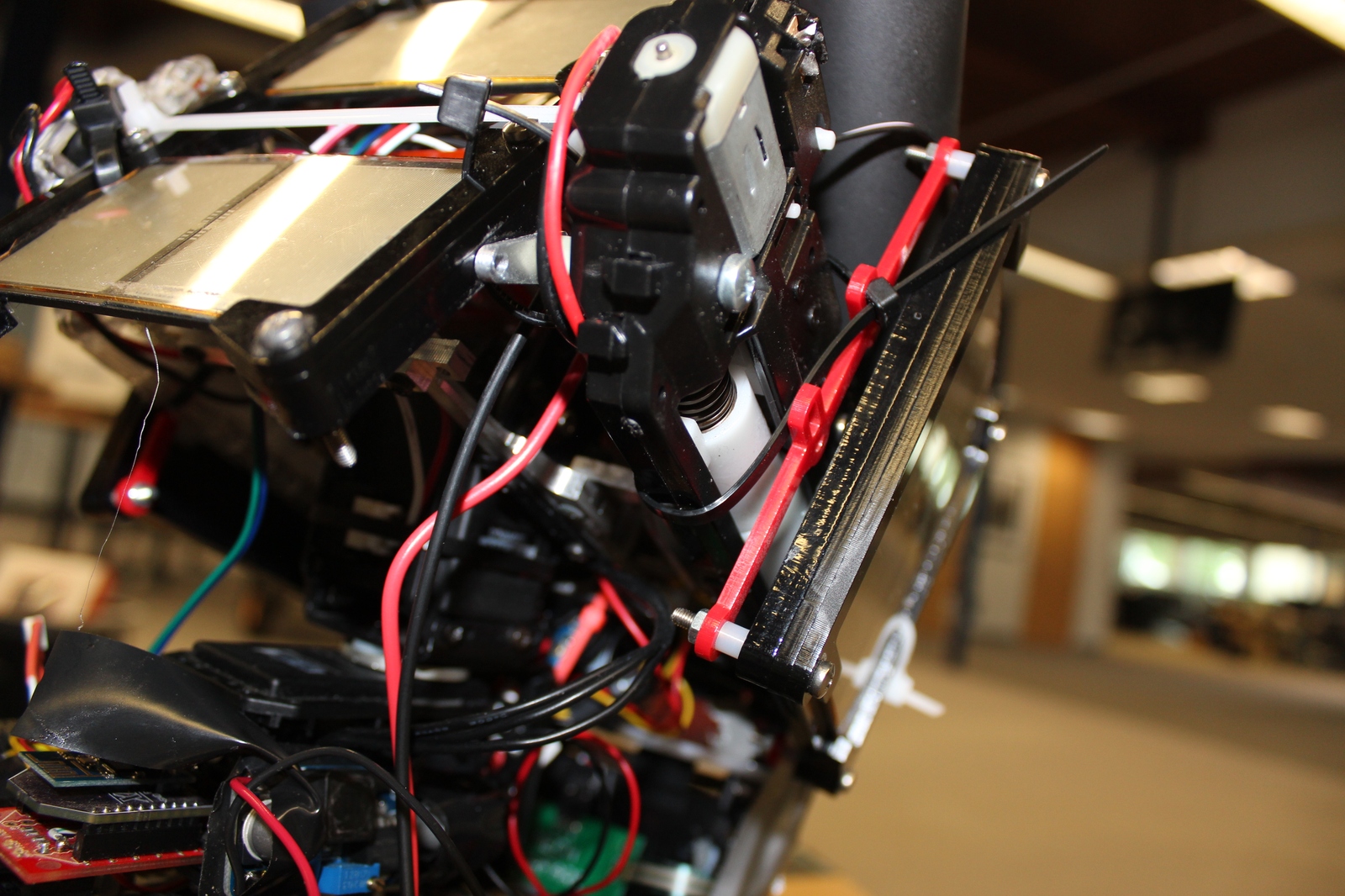
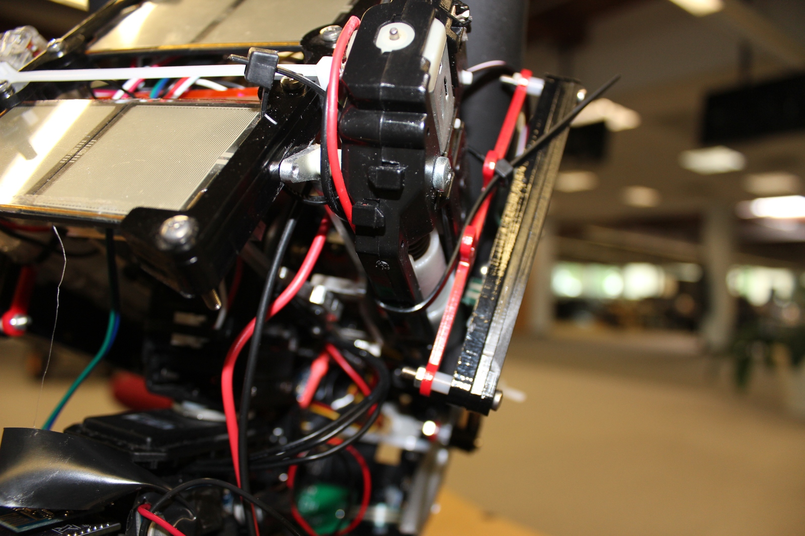
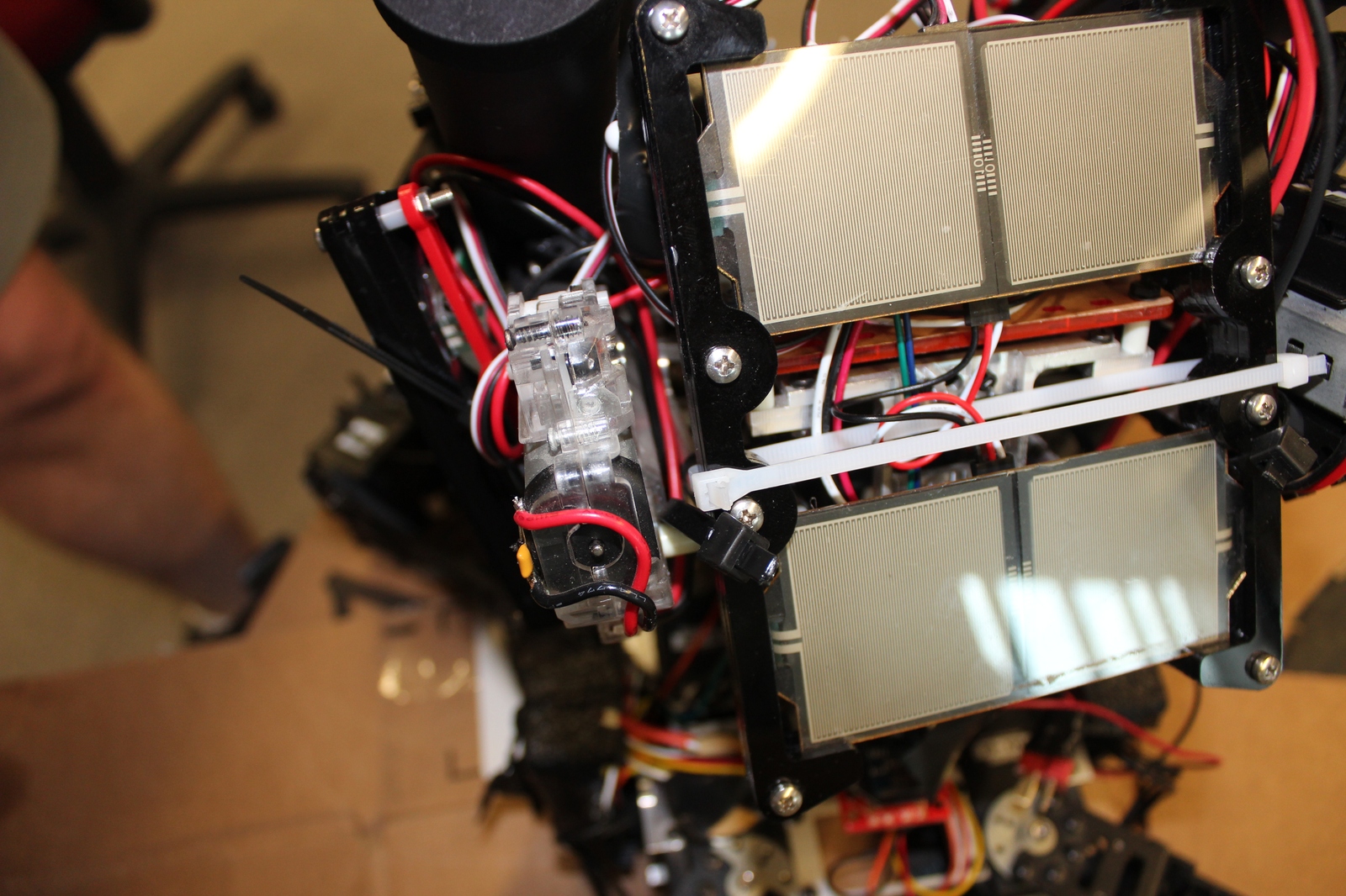
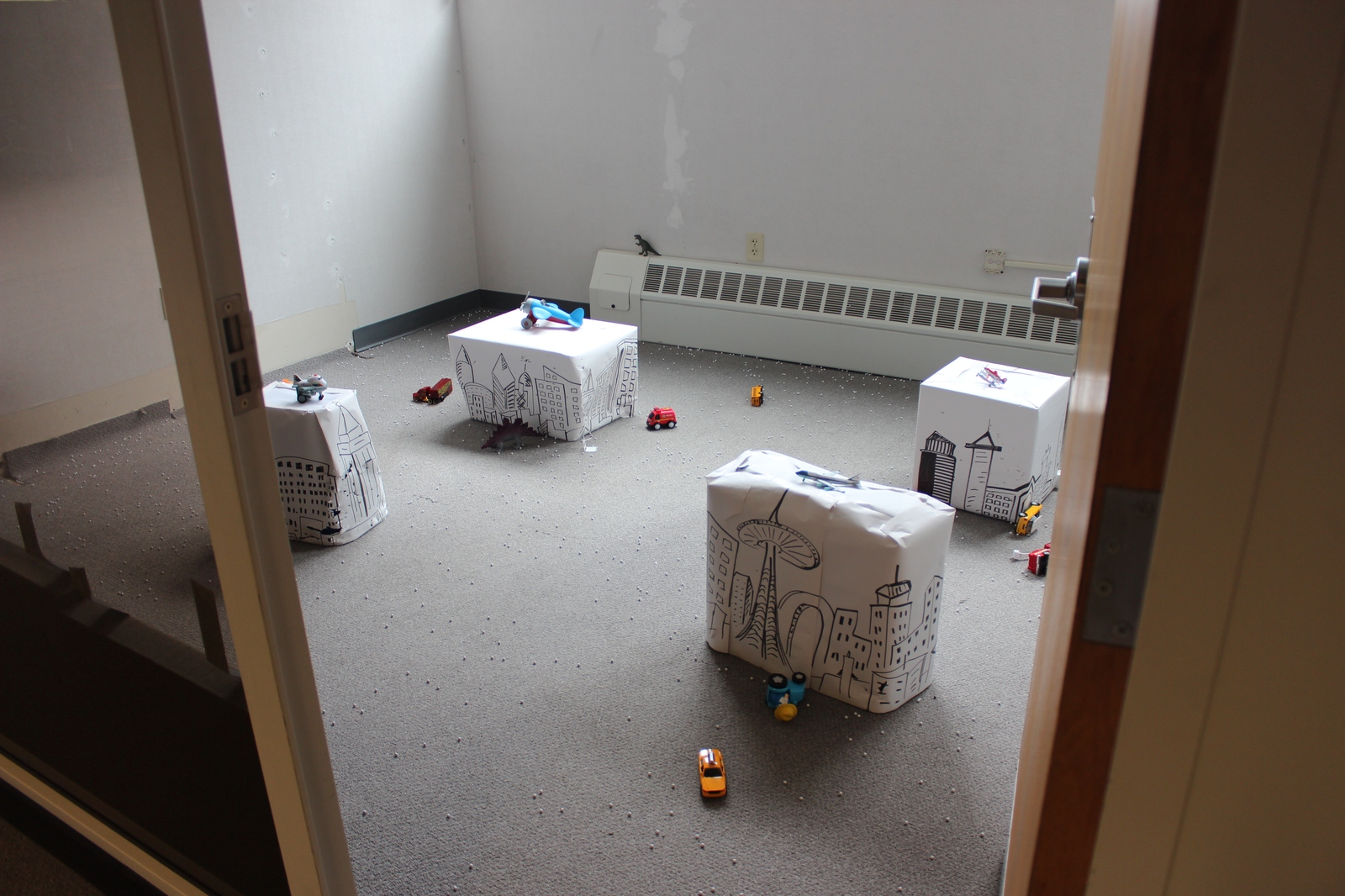
Stabilized camera: The new gimbal stabilized turret actually worked really well. We were able to reliably hit moving targets from the full length of the arena while in motion. It still has room for improvement, but overall was very reliable.
5GHz Video transport: We updated our video to use a custom protocol over multicast 5GHz wifi, so that we could completely control the amount of link layer retransmissions. When it worked, this worked very well. We were able to get 720p video with 200ms latency, even in the presence of significant interference. However, adding the external 5GHz wifi card to our odroid seems to have made the USB bus overall somewhat unstable, and one of our matches ended prematurely when the entire USB port died, taking our camera and wifi with it.
Matches
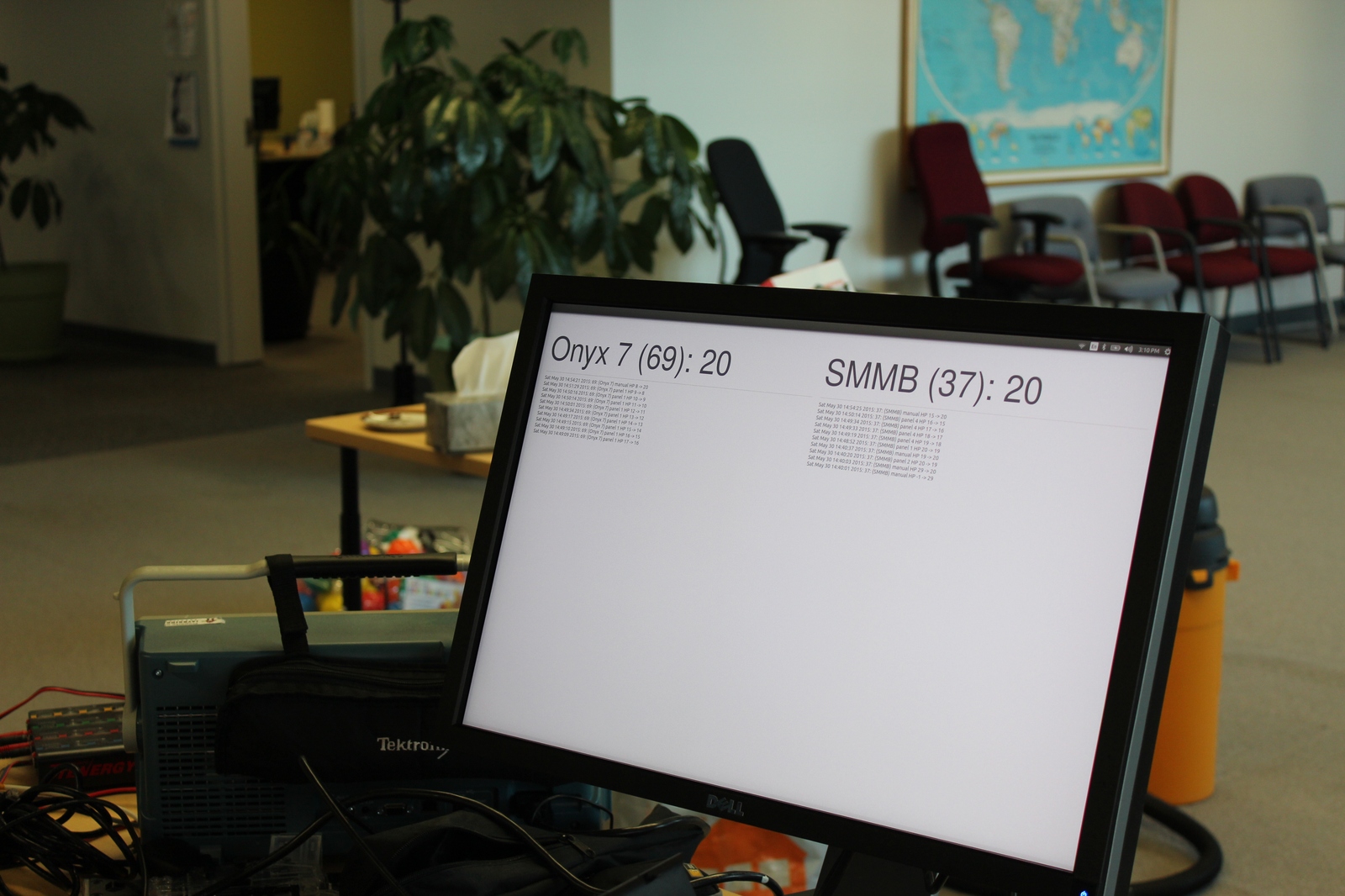
Thanks to Kevin from R-TEAM, we managed to capture overhead video of all our matches, and have the video as seen on our operator console for each official match as well.
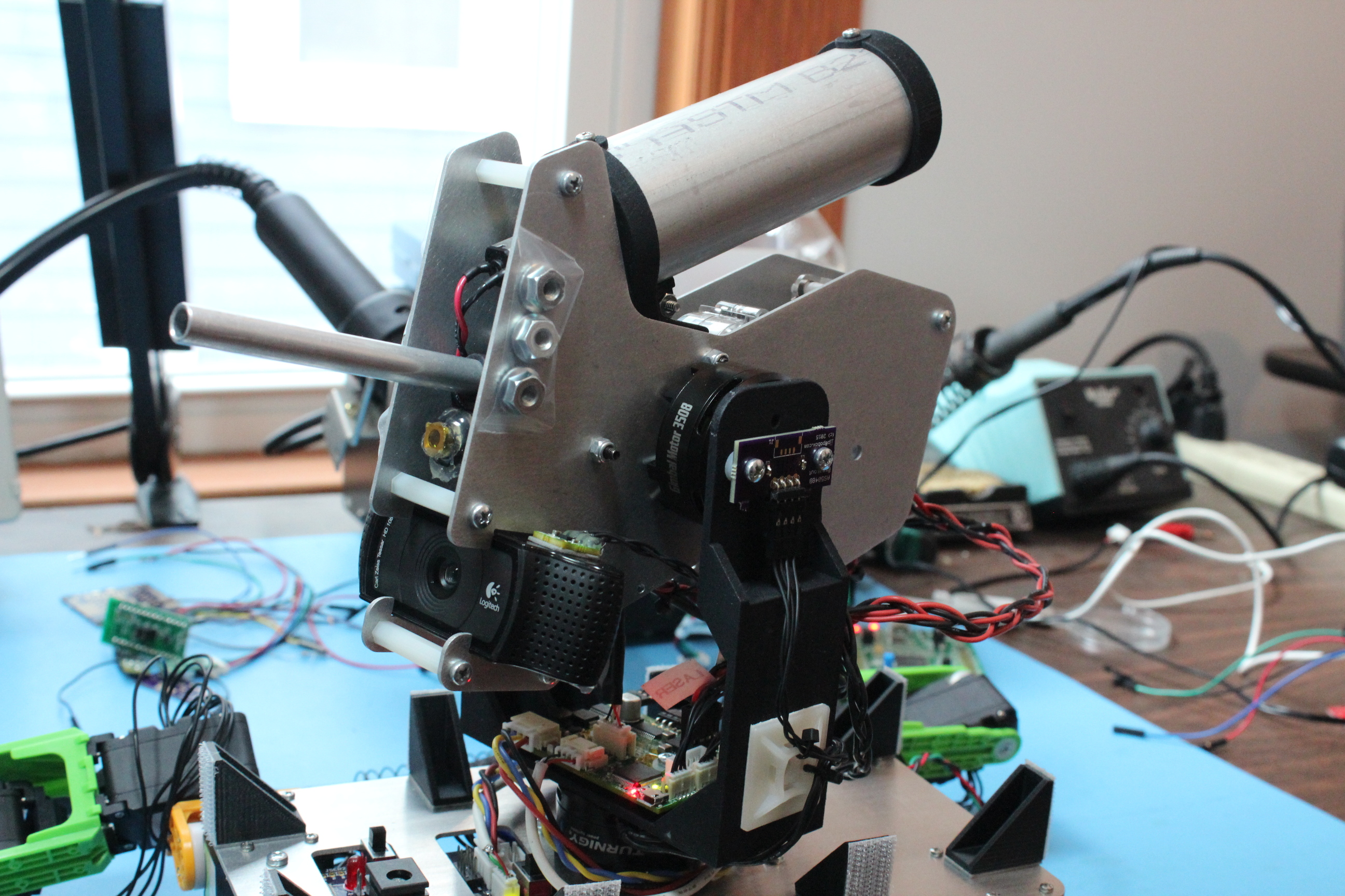
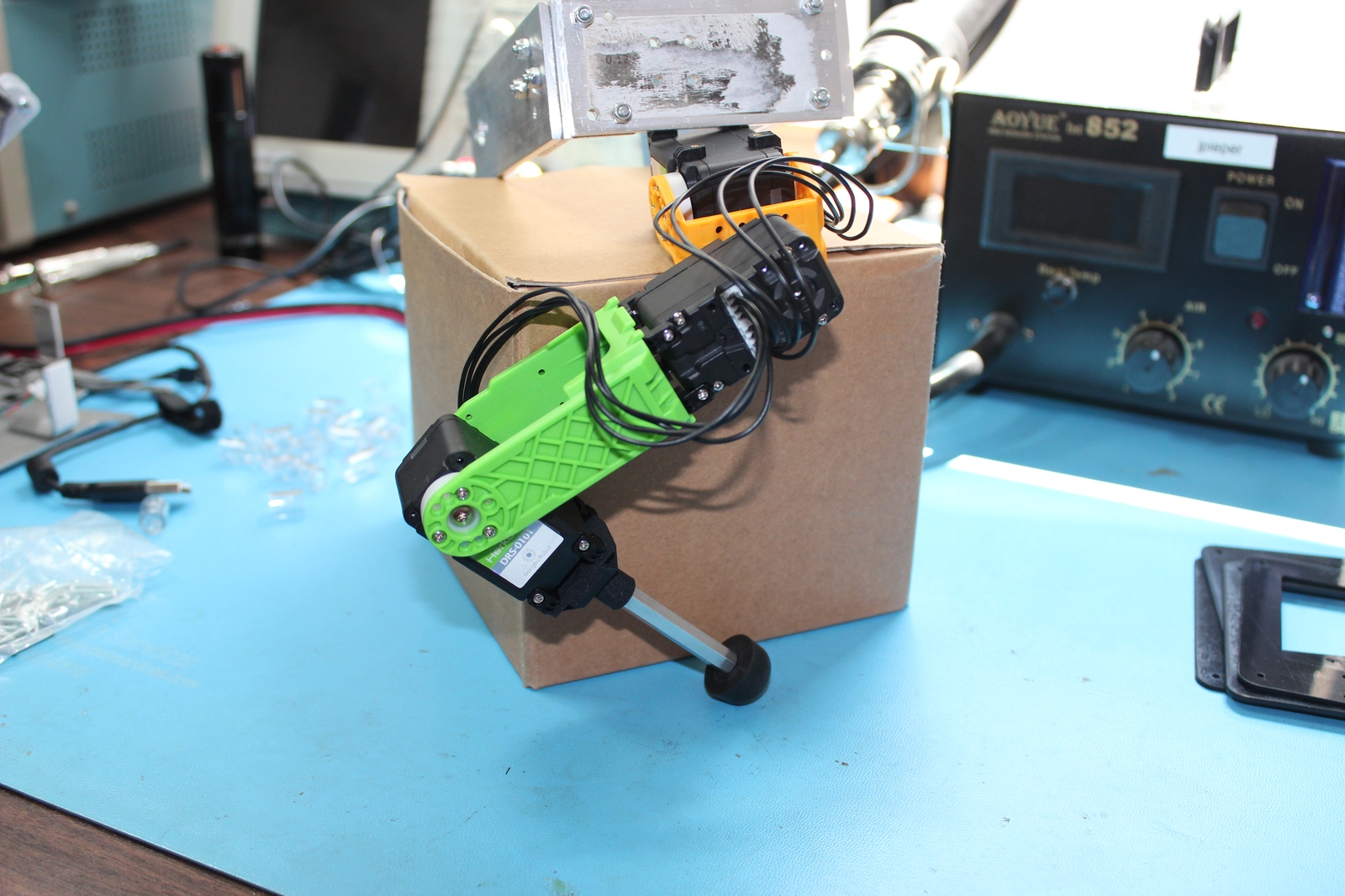
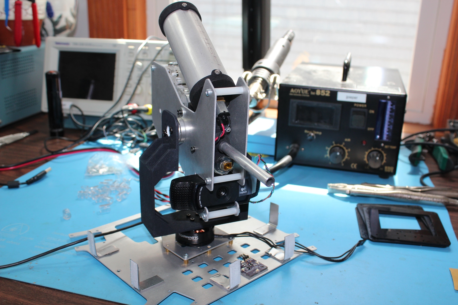
Well, that took longer than I expected! I last showed some progress on a gimbal stabilized turret for Mech Warfare competitions more than six months ago. Due to some unexpected technical difficulties, it took much longer to complete than I had hoped, but the (close to) end result is here!
Complete gimbal mounted turret
Here’s a quick feature list:
2 axis control: Yaw and pitch are independently actuated.
Brushless: Each axis is driven by a brushless gimbal motor for high bandwidth no-backlash stabilization.
Absolute encoders: Each axis has an absolute magnetic encoder so that accurate force control can be applied to each gimbal, even at zero speed.
Fire control: High current outputs for driving an AEG motor, an agitator motor, and a low current output for a targetting laser are present.
7v-12V input: Supports 2S-3S lipo power sources.
12V boost: When running from 2S lipo, it can boost the gimbal drive up to 12V for additional stabilization authority.
HerkuleX protocol: The primary control interface uses a native Dongbu HerkuleX protocol; support for other UART based protocols which will work at 3.3V CMOS levels should be easy.
USB debugging support: A USB port is present to return high rate debugging information and allow configuration and diagnostics to be performed.
AS5048A/B: These absolute magnetic encoders are used to measure the actual position of the pitch and yaw gimbals.
BMI160: This IMU is used as the primary source of inertial compensation data. The board hardware supports a second IMU, to be placed on the main robot, but the firmware does not yet support that configuration.
Boards
This gimbal design contains three custom boards, a breakout board for the BMI160 IMU, a breakout board for the AS5048B magnetic encoder sensor, and the primary board which contains the rest of the logic.
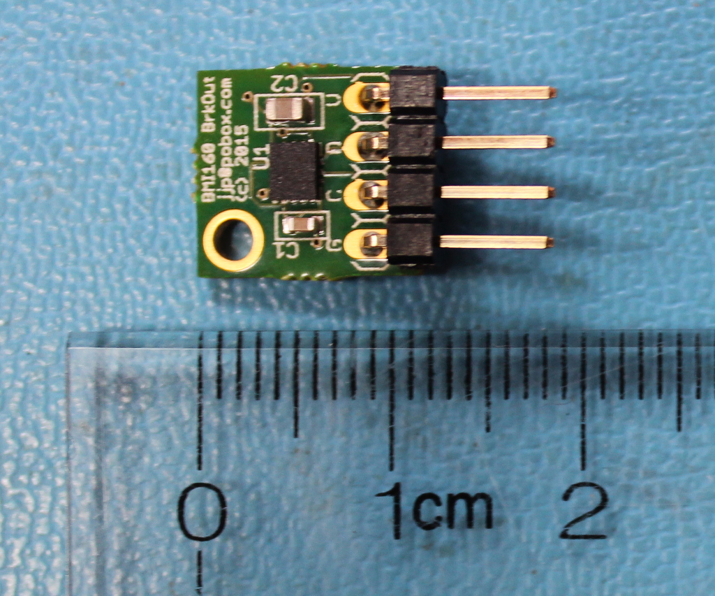
BMI 160 Breakout
Completed BMI160 breakout board, Assembled by MacroFab
The first board is simple; it is a basically just a breakout board for the BMI160 inertial sensor. It provides the BMI160 itself, some decoupling capacitors, and a 0.1 inch 4 pin connector for the I2C bus.
I had these prototypes made at MacroFab which I highly recommend as a great provider of low-cost turnkey PCB assembly.
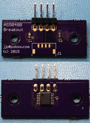
AS5048B Breakout
AS5048B breakout board
This, like the BMI160 breakout board, just has decoupling capacitors, the chip itself, and connectors. It additionally has mounting holes designed to fit onto the 3508 gimbal motor. This was printed at OSH Park and hand-assembled.
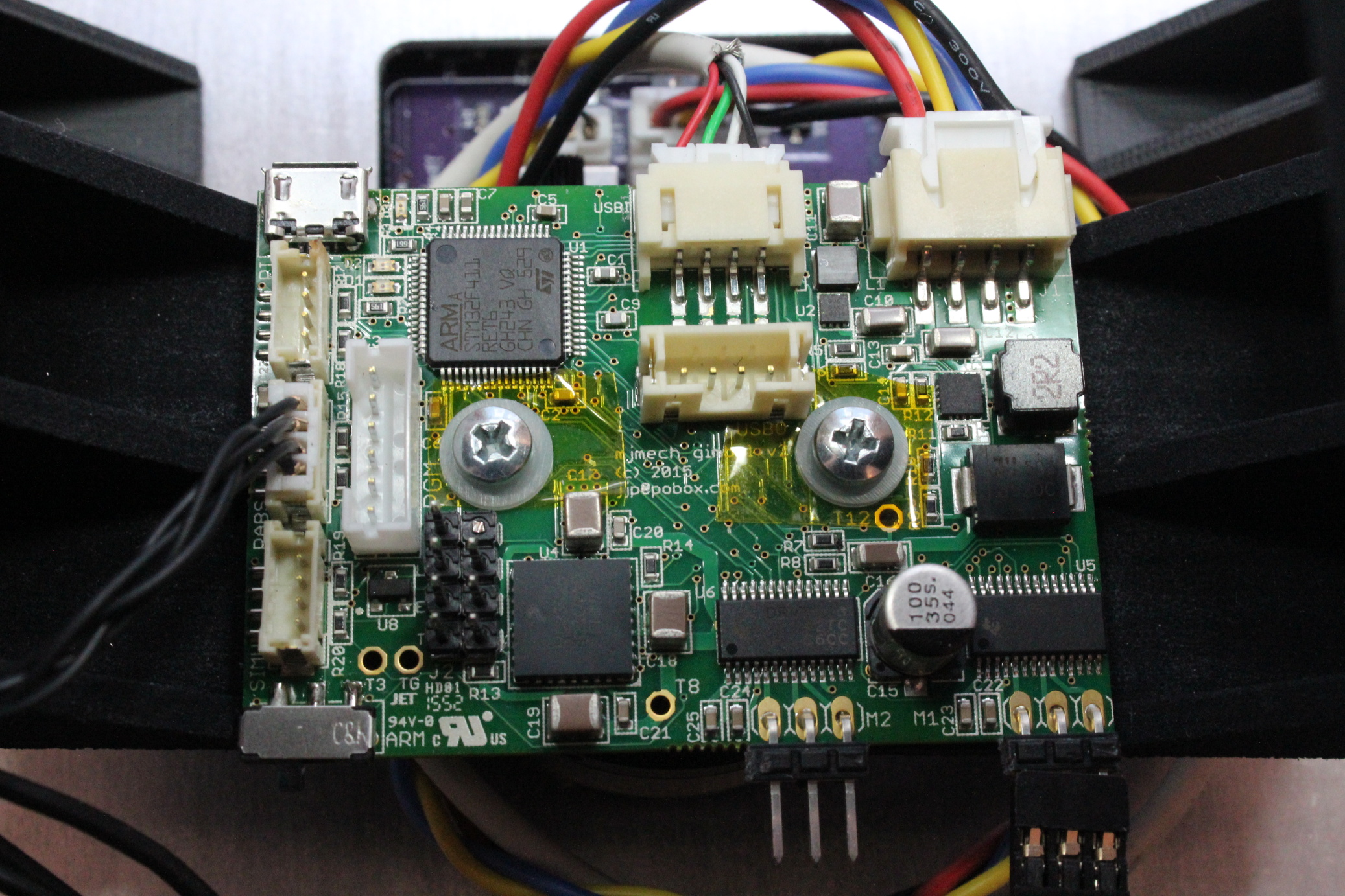
Gimbal control board
Completed primary gimbal control board (r2) , Assembled by MacroFab
The primary gimbal control board contains most of the system functionality. It is designed to mechanically mount directly above the yaw gimbal motor, as the yaw absolute magnetic encoder is in the center on the underside of the board.
This prototype was also built at MacroFab, who did an excellent job with this much more complex assembly.
The connectors and features are as follows:
Power and Data: A 4 pin JST-XH connector in the upper right brings in power and data from the main robot.
Debug USB: A debugging protocol is available on this micro-USB port.
Camera USB: Two 4 pin JST-PH connectors provide a convenience path for the camera USB. The turret’s camera connects to the top connector, and the main robot connects to the side facing connector.
I2C peripherals: 3, 4 pin JST-ZH connectors have identical pinout and connect to external I2C peripherals. These are used for the primary IMU, the pitch absolute magnetic encoder, and the optional secondary IMU.
Arming switch: This switch is connected directly to the enable pin on the MC33926, and is also connected to an input on the STM32F411.
Programming connector: The 6 pin JST-PH connector has the same pinout as Benjamin Vedder’s VESC board, and can program and debug the STM32F411.
Weapon connector: A 2x4 0.1 inch pin header has power lines for the AEG drive, the agitator drive and the laser. It has an extra row of pins so that a blank can be used for indexing.
Gimbal connectors: 2, 3 pin 0.1 inch connectors power the yaw and pitch gimbal brushless motors.
The firmware was an experiment in writing modern C++11 code for the bare-metal STM32 platform. Each module interacts with others through std::function like callbacks, and the entire system is compiled both for the target, and the host so that unit tests are run. Dynamic memory allocation is this close to being disabled, but it was necessary for newlib’s floating point number formatting routines, which just allocate a chunk of memory the first time you use them. Otherwise, there is no dynamic memory used at all.
It relies on a CubeMX project template for this board. Most of the libraries CubeMX provides have too little flexilibity to be used for this application, so much of the bit twiddling is re-implemented in the gimbal firmware. CubeMX is great for configuring the clock tree and pin alternate functions however, especially in a complex project like this.
Both configuration and telemetry rely on a templated C++ visitor pattern to perform compile time reflection over mostly arbitrary C++ structures. Any module can register a structure to be used for persistent configuration. Those structures can be changed through the debugging protocol, and can be written to and read from flash at runtime. Each module can also register as many telemetry structures as necessary. These can be emitted over the debugging protocol either at fixed intervals, or whenever they update.
There are three possible modes, the first of which is what I call “open-loop”, and is based on the same principles as the BruGi brushless gimbal, where no absolute motor feedback is available. In that mode, a PID controller operates with the axis error as the input, and the output is the actual phase position of the BLDC controller. In this mode, the integral term does most of the work in stabilization, so the overall performance isn’t great.
The second mode still uses a PID controller, but now the output is an offset to the BLDC phase necessary to hold the current position as measured by the absolute encoders. This effectively makes the output a direct mapping to force applied to the motor, although of course a non-linear mapping. This mode results in much better overall performance and is easier to tune.
Finally, there is a third debugging mode that lets you just hard command specific BLDC phases. This is useful for calibrating the mapping between BLDC phase and absolute encoder phase.
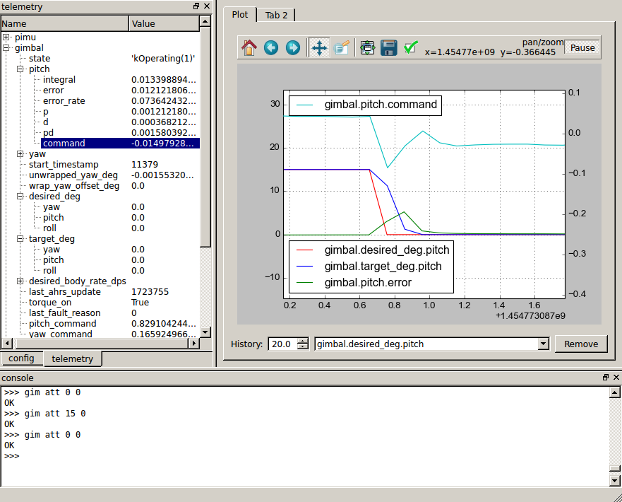
tview
The debugging protocol is partially human readable, but telemetry data is encoded in the same binary format as used elsewhere in the mjmech codebase. tview is the debugging application we use to read that data, as well as configure and control the overall system.
tview window
The bottom pane just has a serial console, where you can send arbitrary things over the virtual serial port. tview directly supports relatively few commands from the debugging protocol, and for instance has no UI to operate the stabilizer or fire control, so for now these are done by hand in that window.
The left pane has two tabs, one with a configuration tree and the other with a telemetry tree. The configuration tree shows all structures which were registered as configurable, and allows you to change them in the live system. The telemetry tree shows all structures registered as telemetry structures, and reports their values live as the system is operating.
The right pane has a live plot window where any of the values in the telemetry tree can be plotted versus time. It is just an embedded matplotlib plot, so all the normal plot interaction tools are available, plus some from mjmech’s tplot, like the ability to pan and zoom the left and right axes independently.
System video
And last but not least, here is a short video demonstrating the turret stabilizing a camera and firing some blanks at a target as our mech walks around.
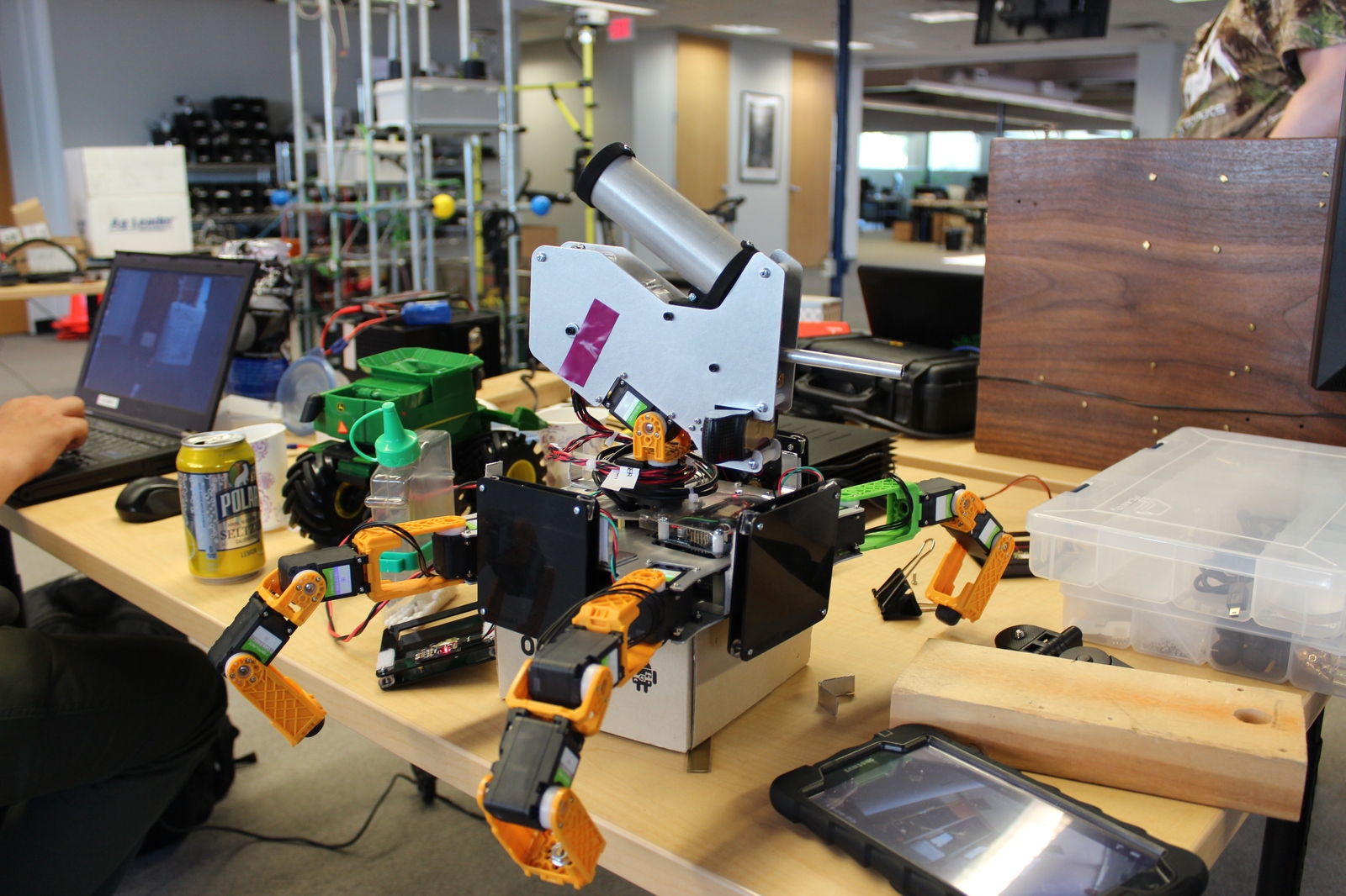
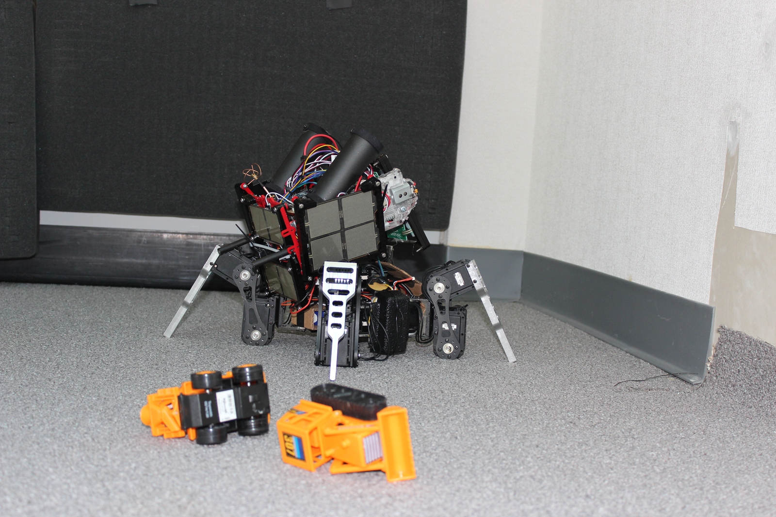
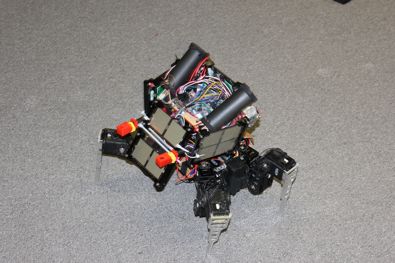
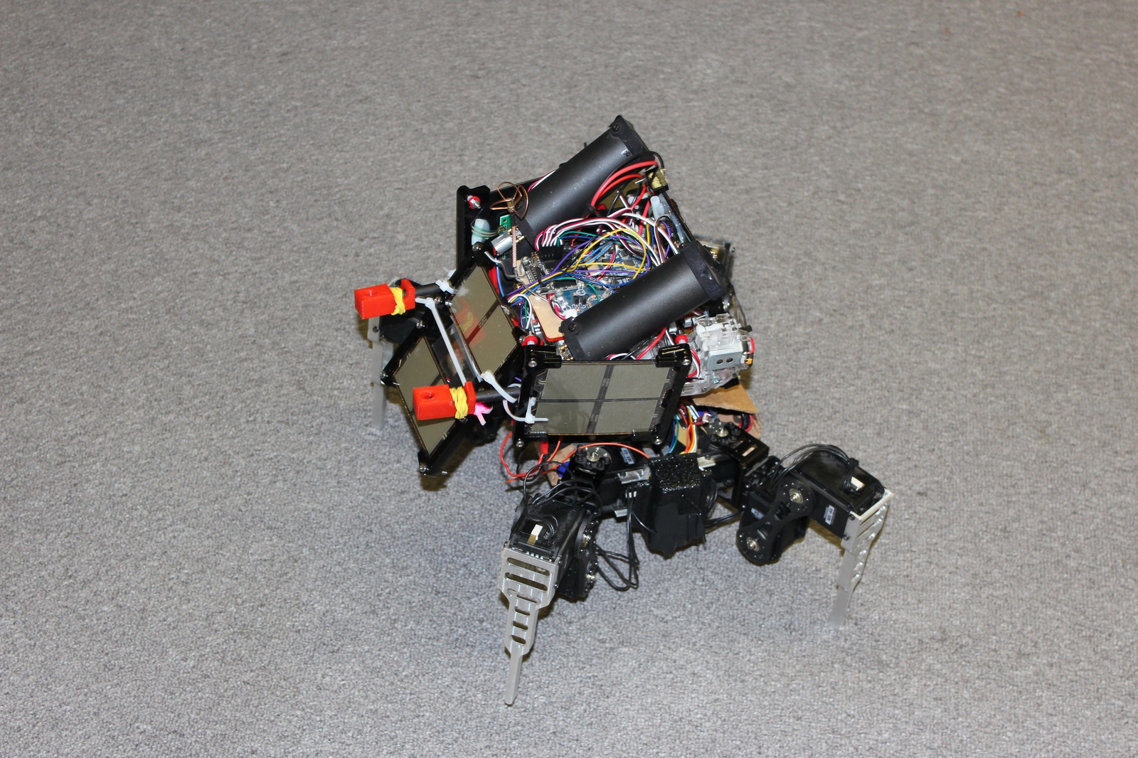
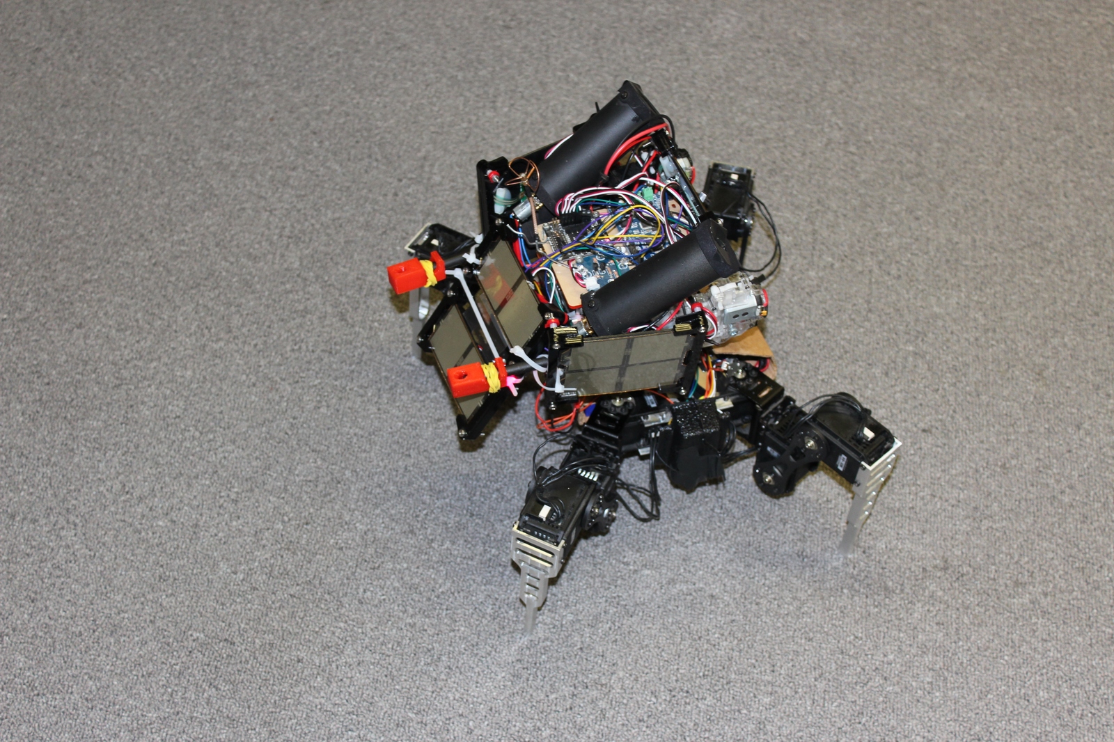
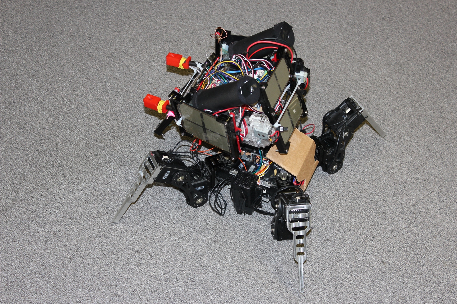
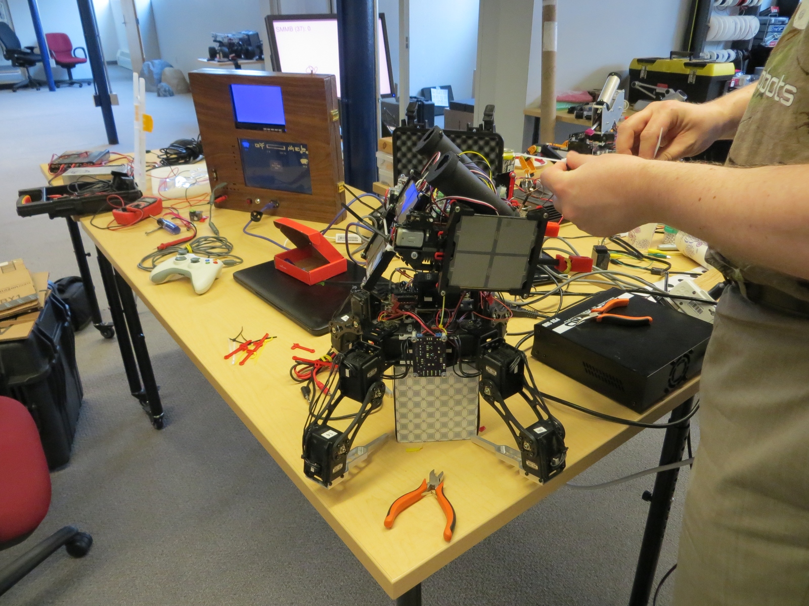
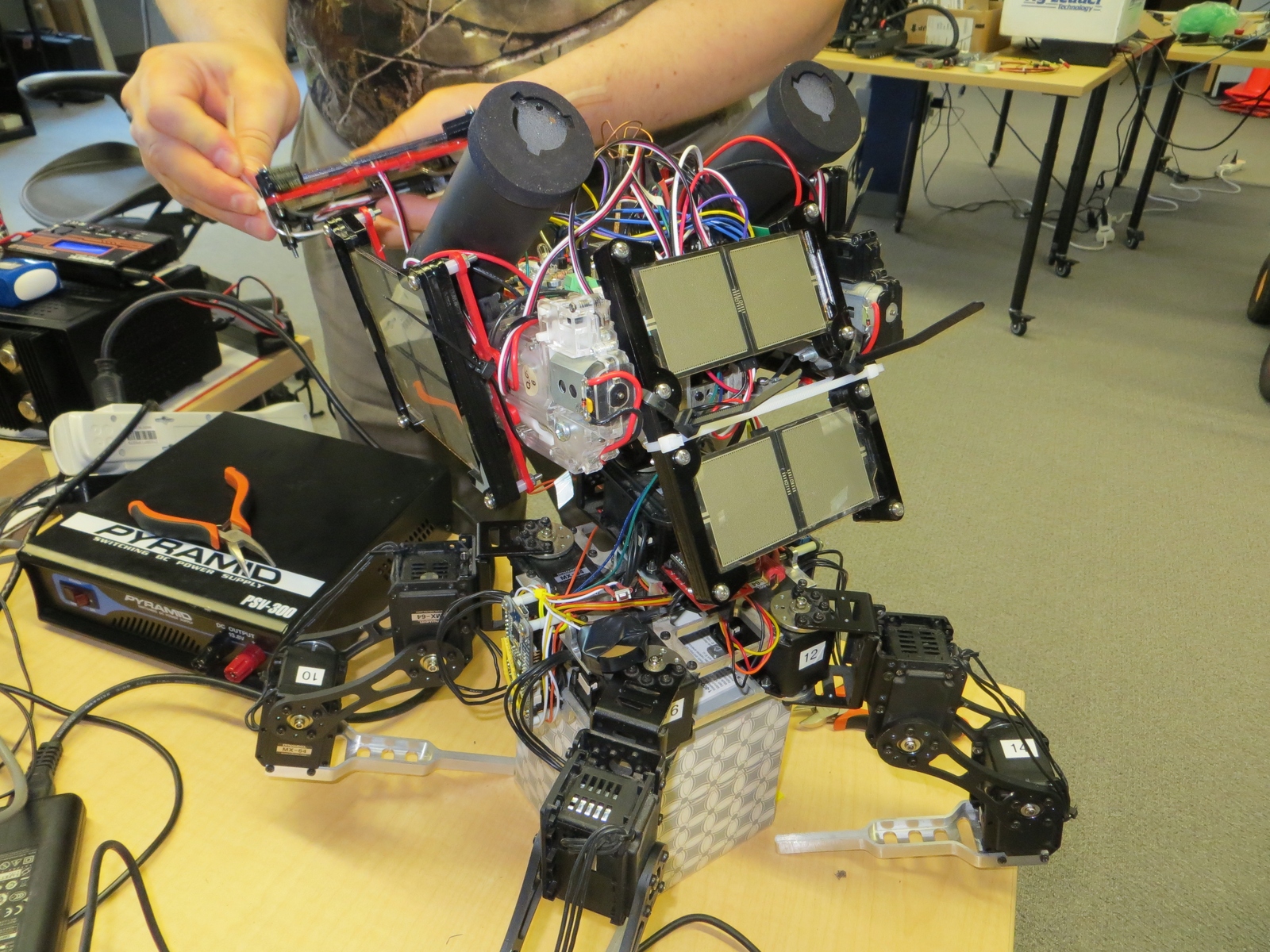
I have some incremental progress to report on various parts of Super Mega Microbot. First, I have a draft fully assembled leg for a mammal walking configuration. It is mostly just the stock Dongbu brackets, with a custom Shapeways print at the final joint holding a standoff and rubber stopper.
Prototype mammal jointed leg
Second, I’ve been working on a gimbal stabilized turret. I have video from a prior incarnation below:
And a first draft of a 3D printed turret bracket that permits a full range of motion of the turret:
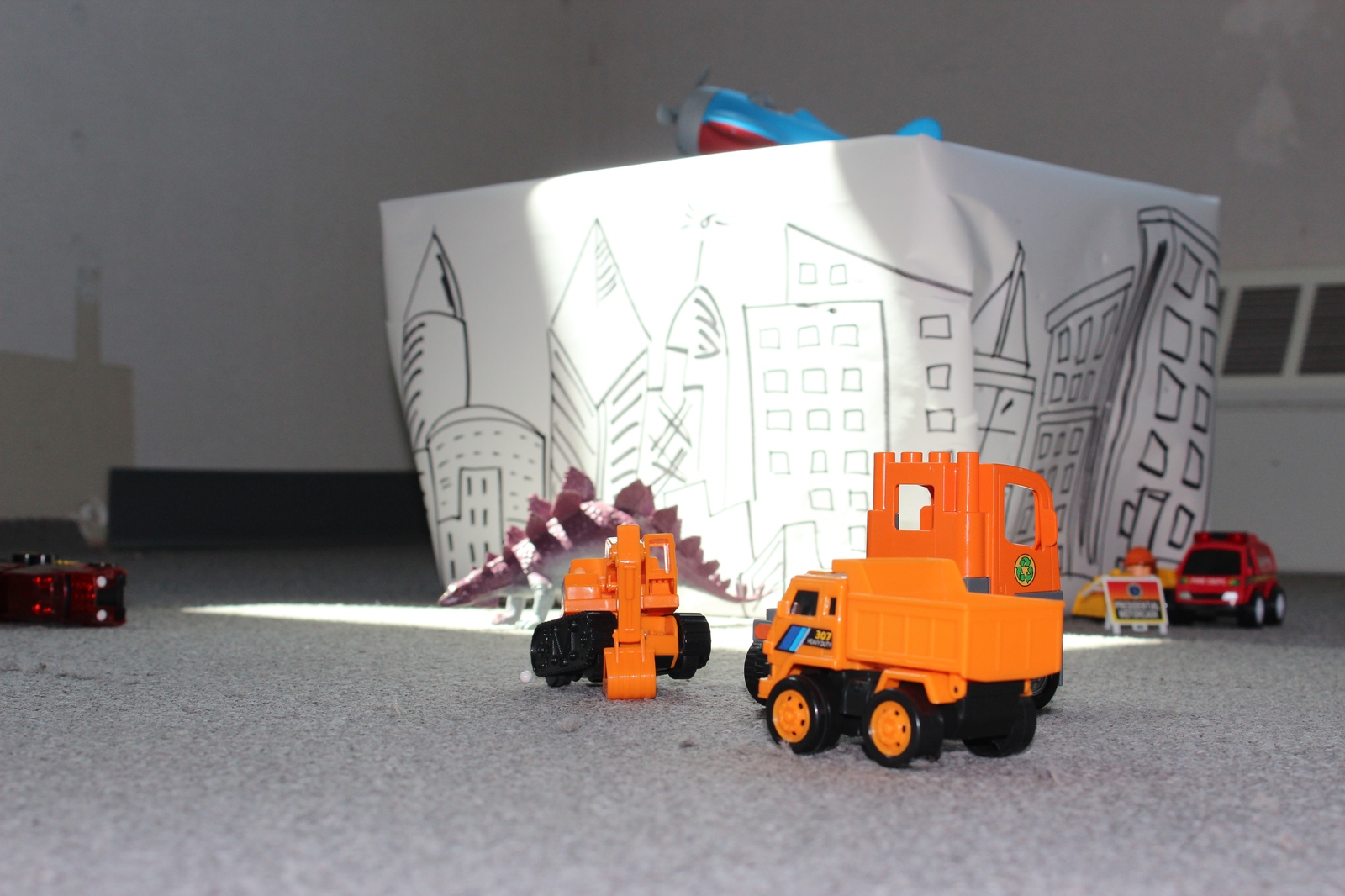
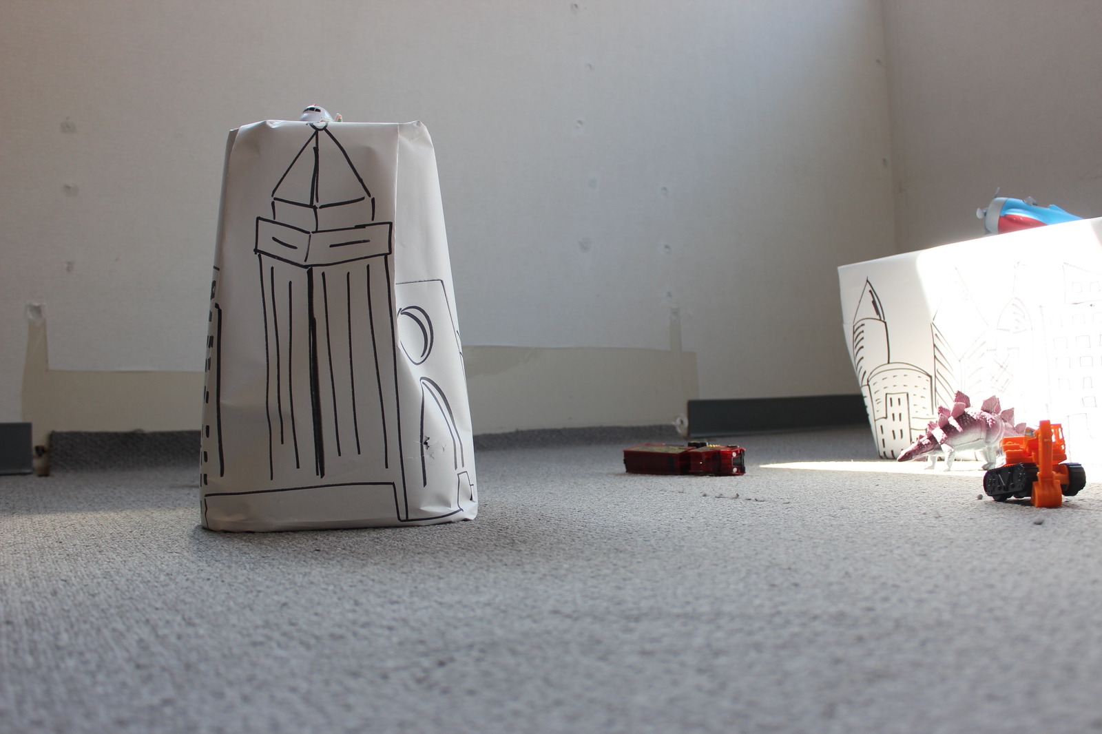
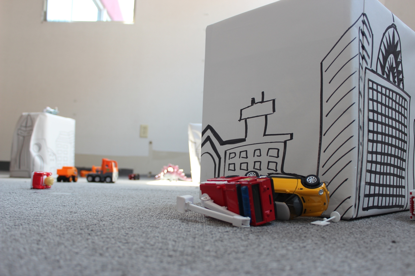
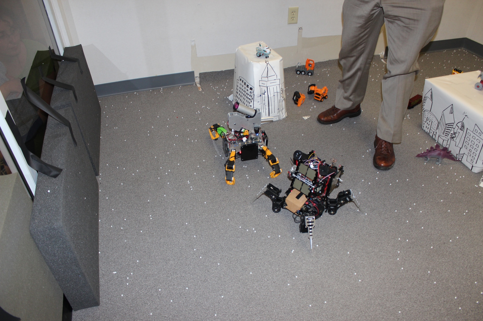
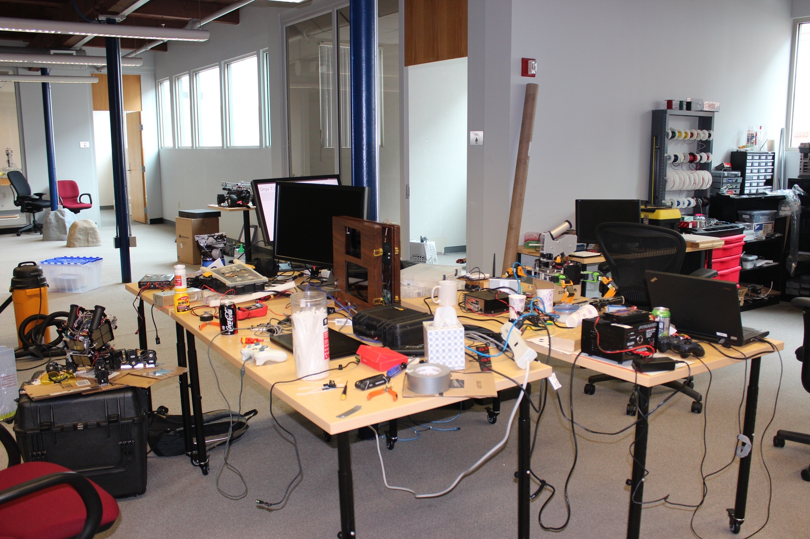
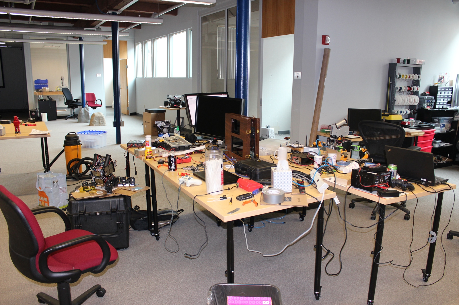
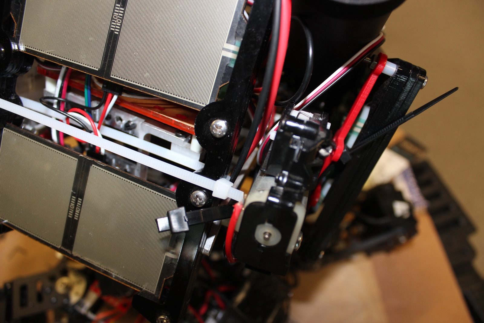
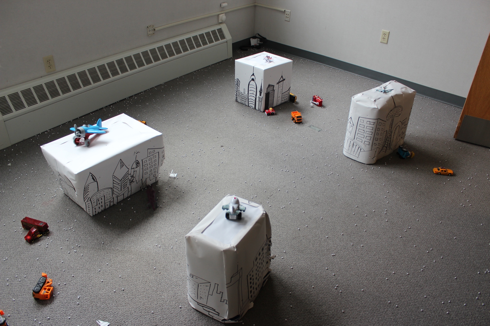
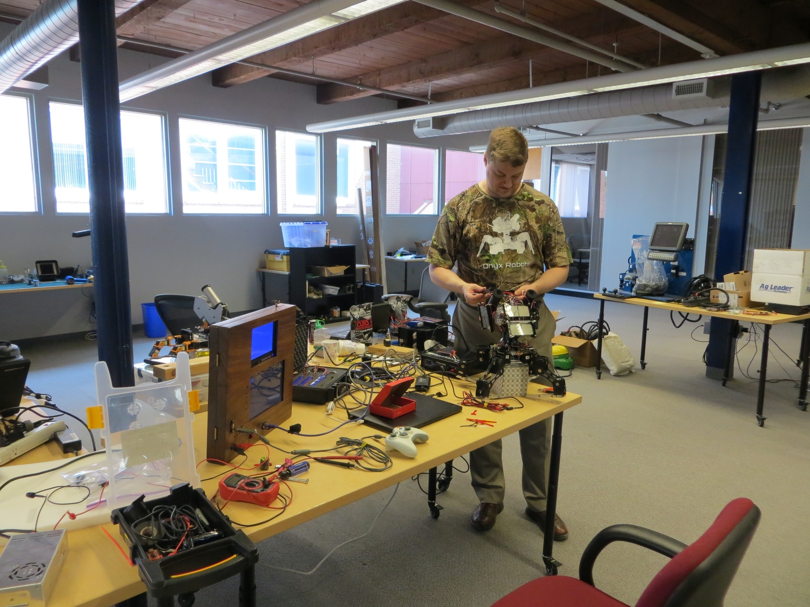
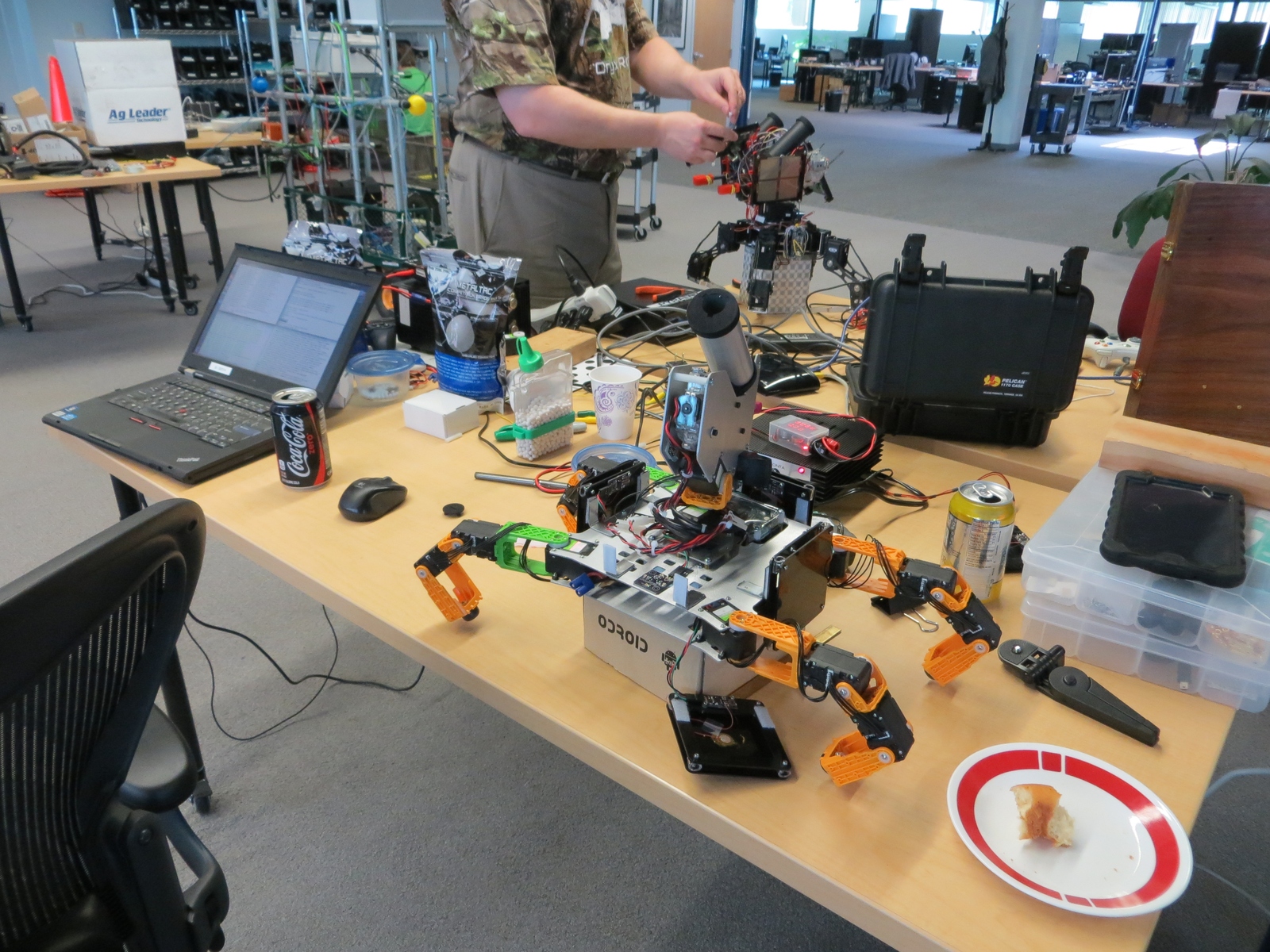
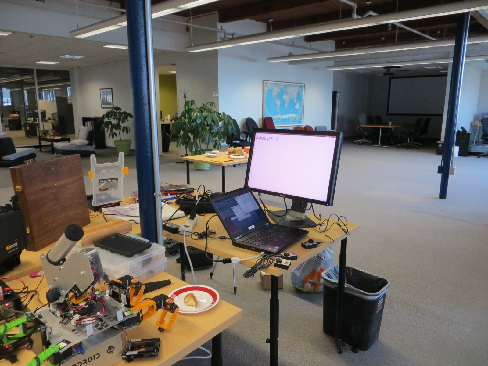
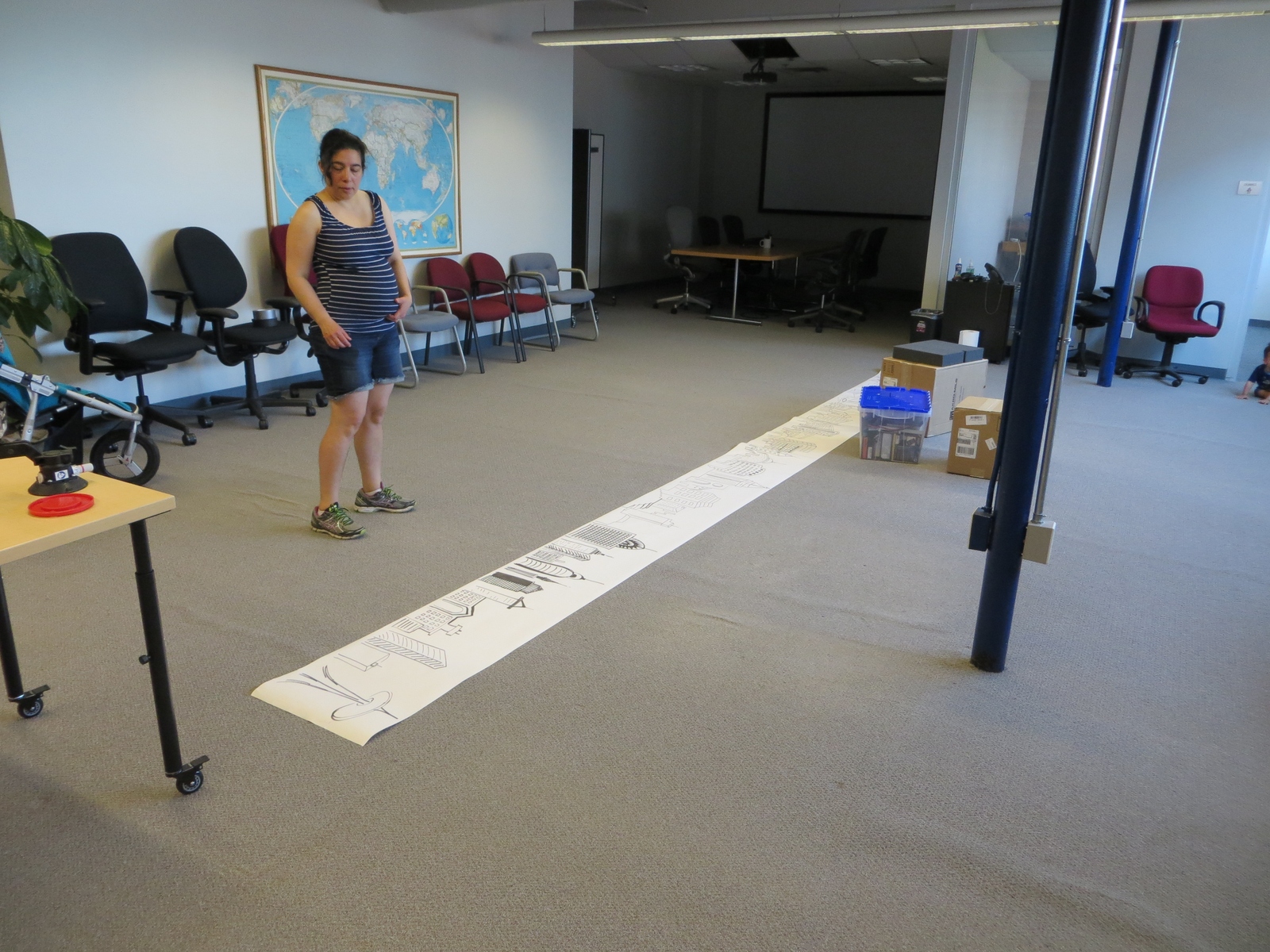
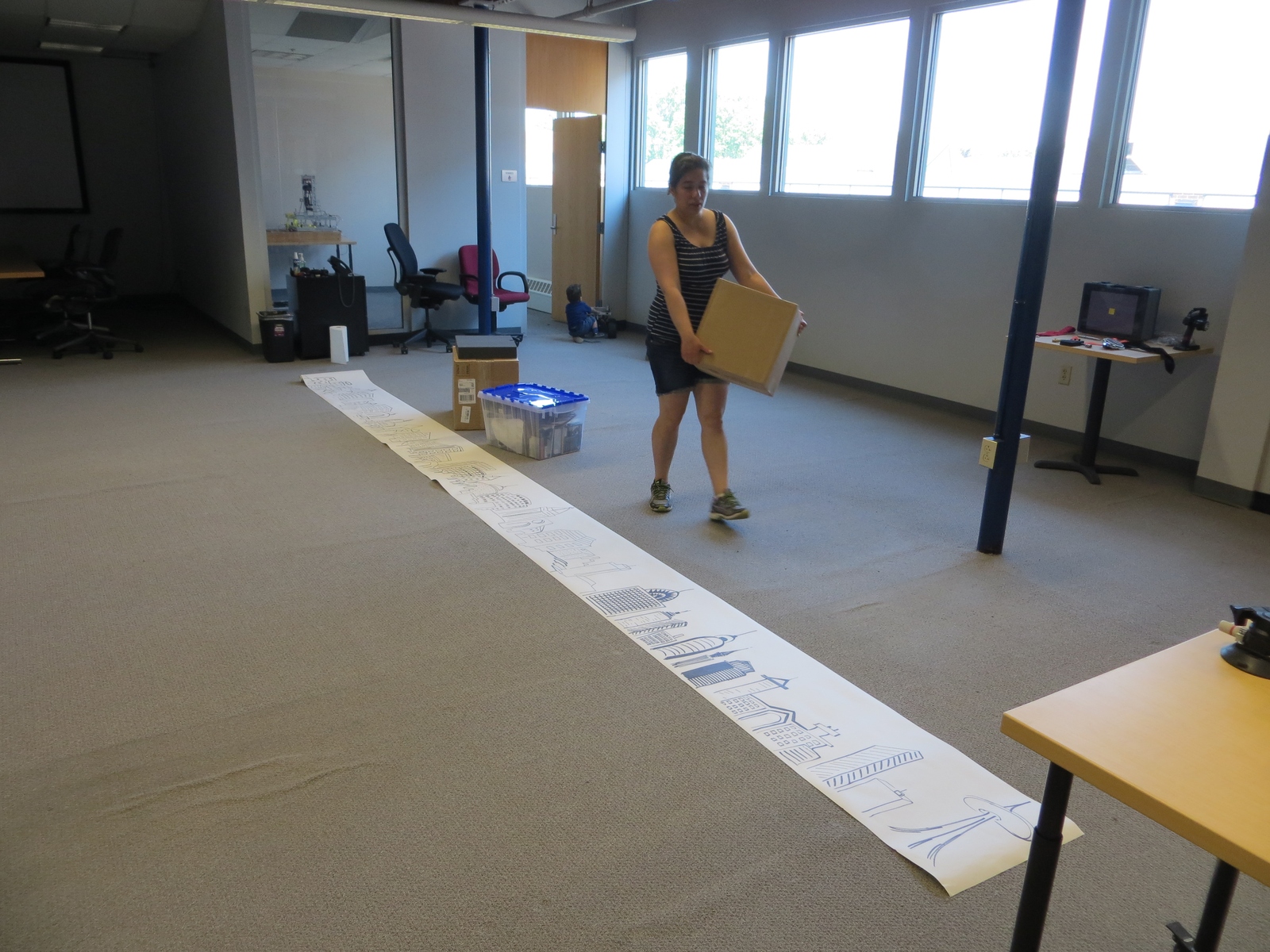
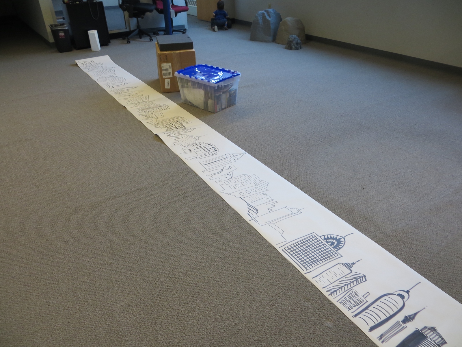
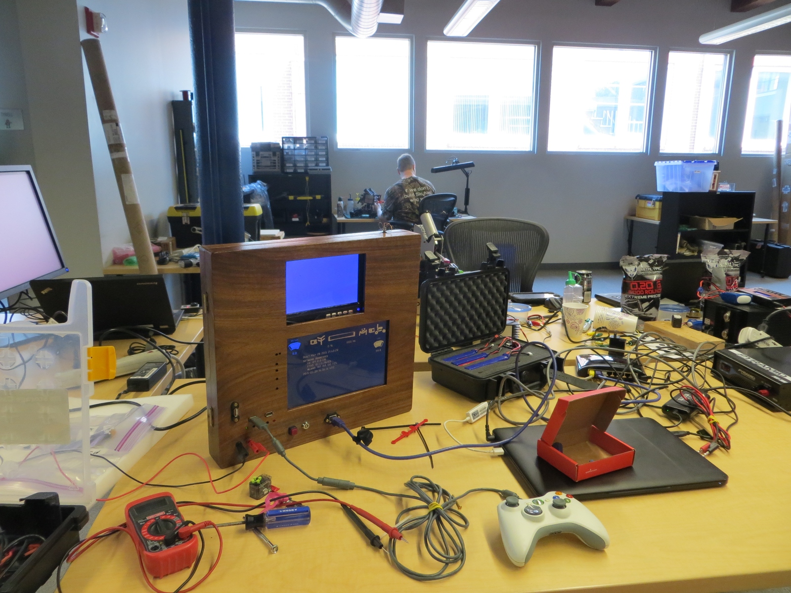
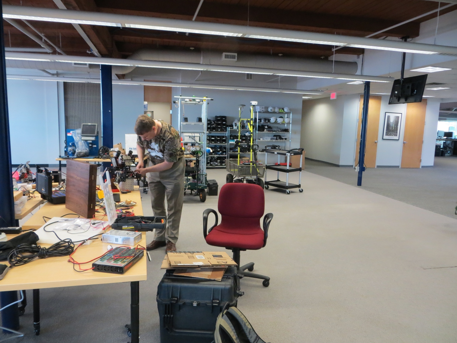
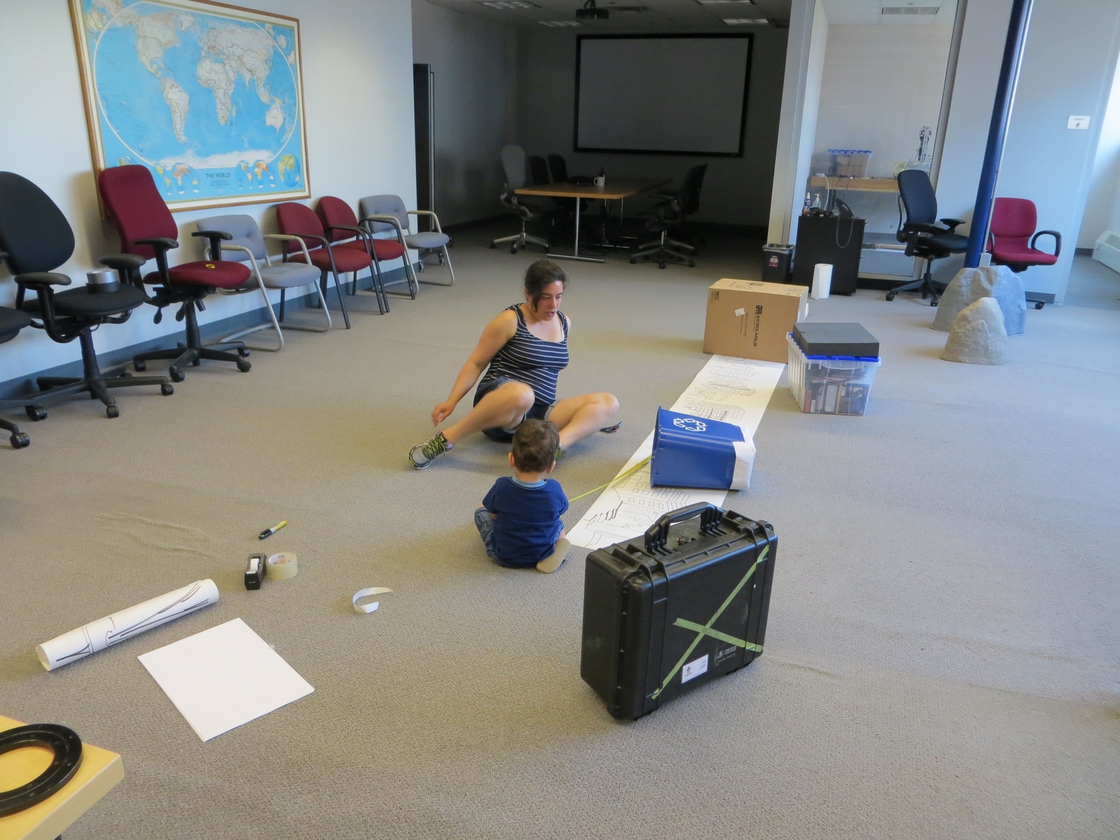
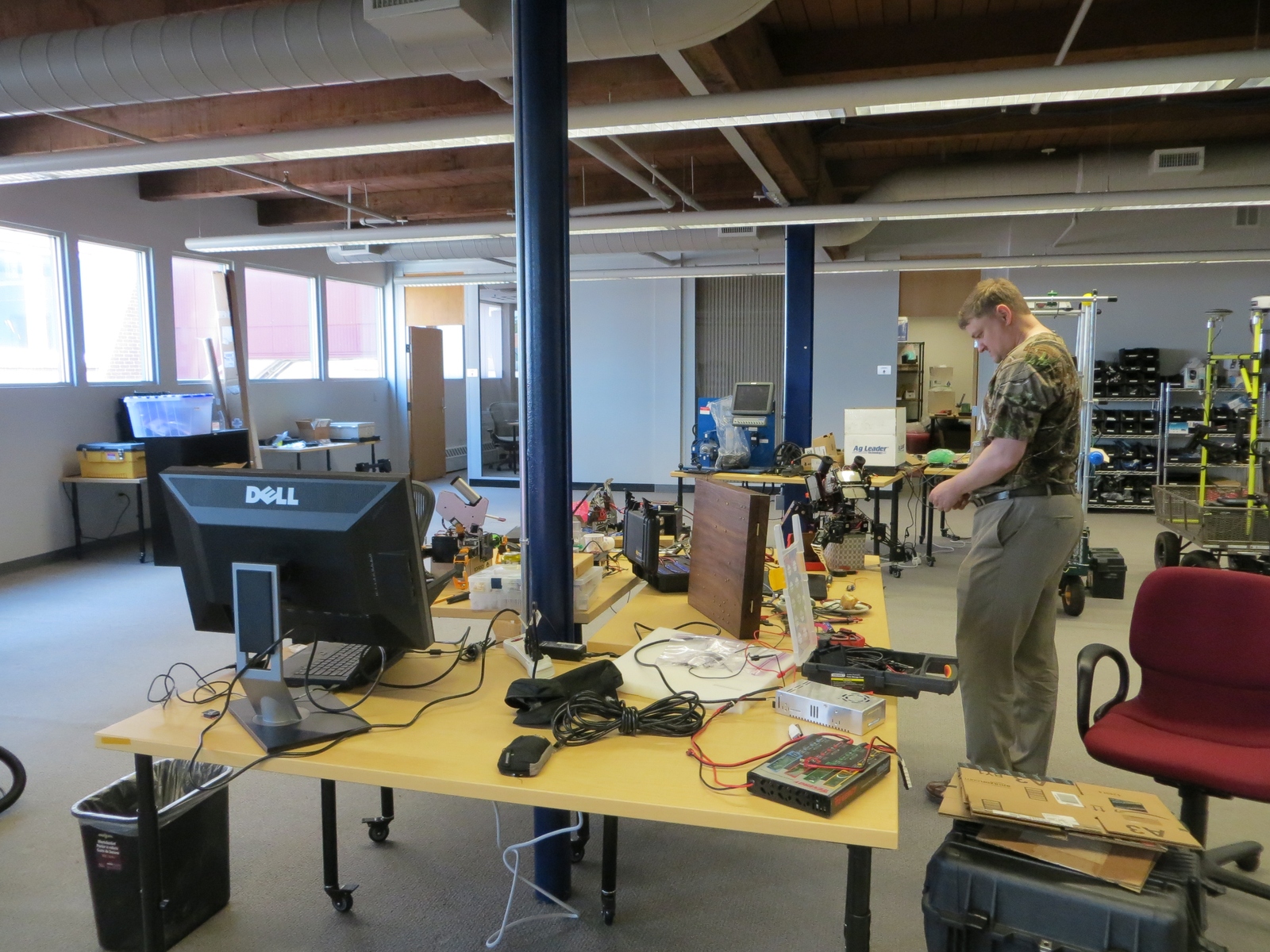
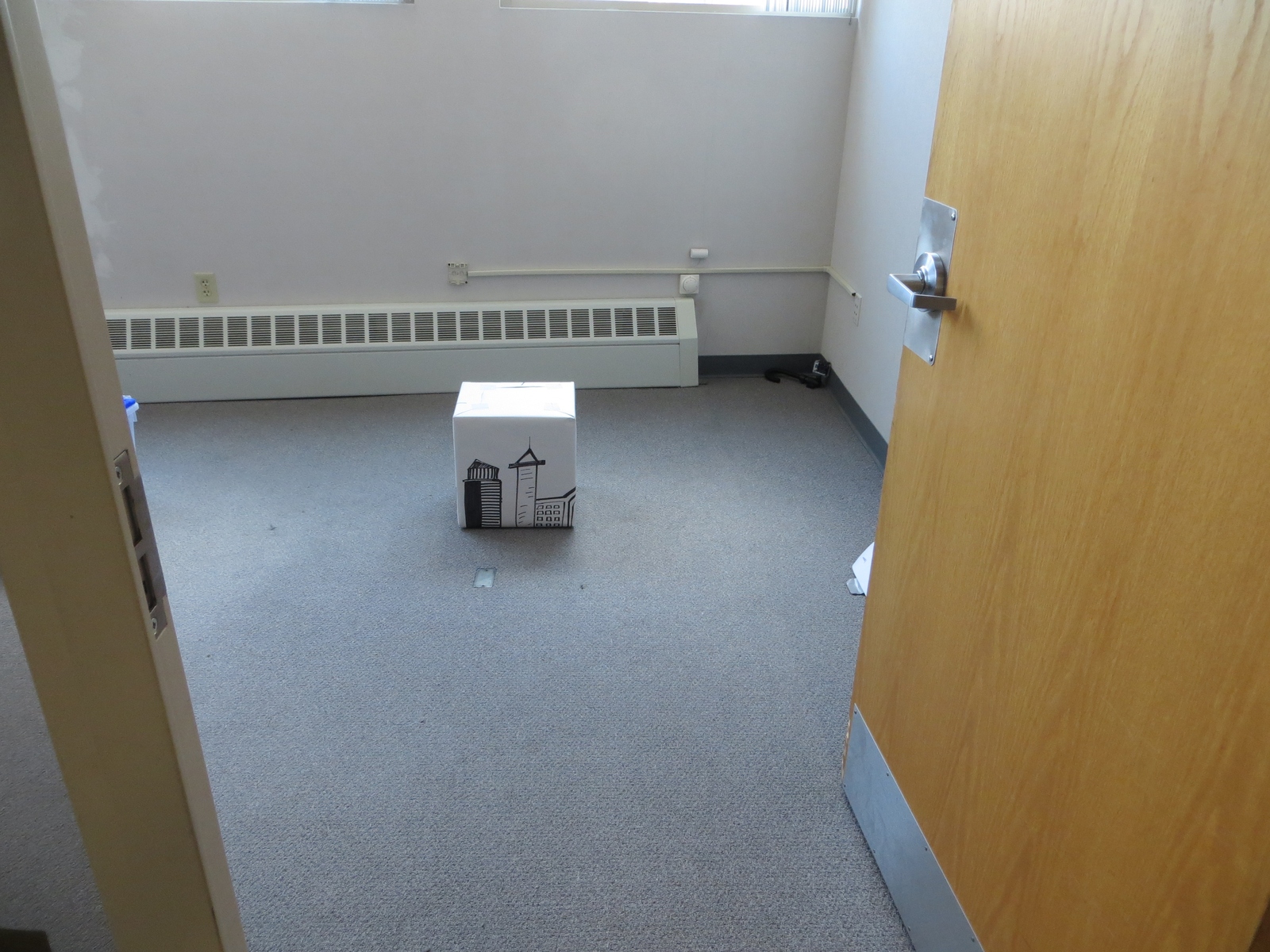
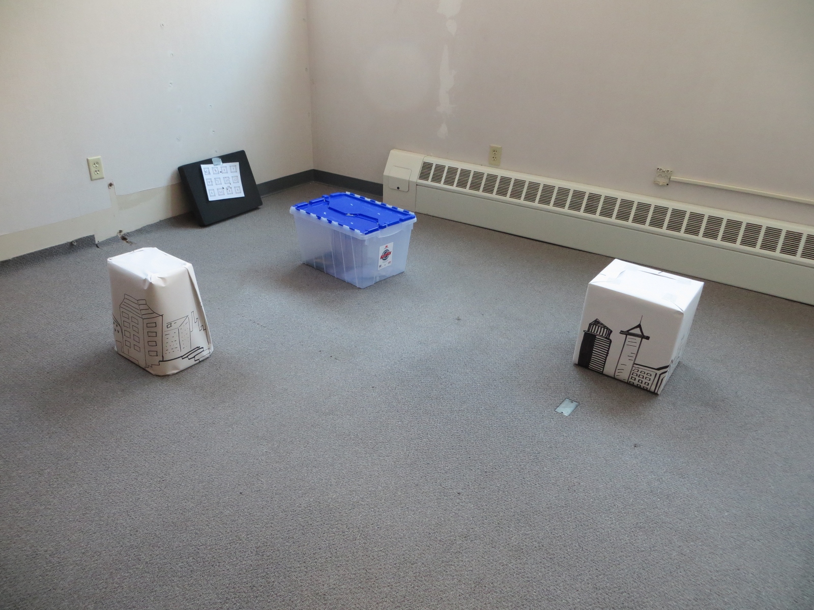
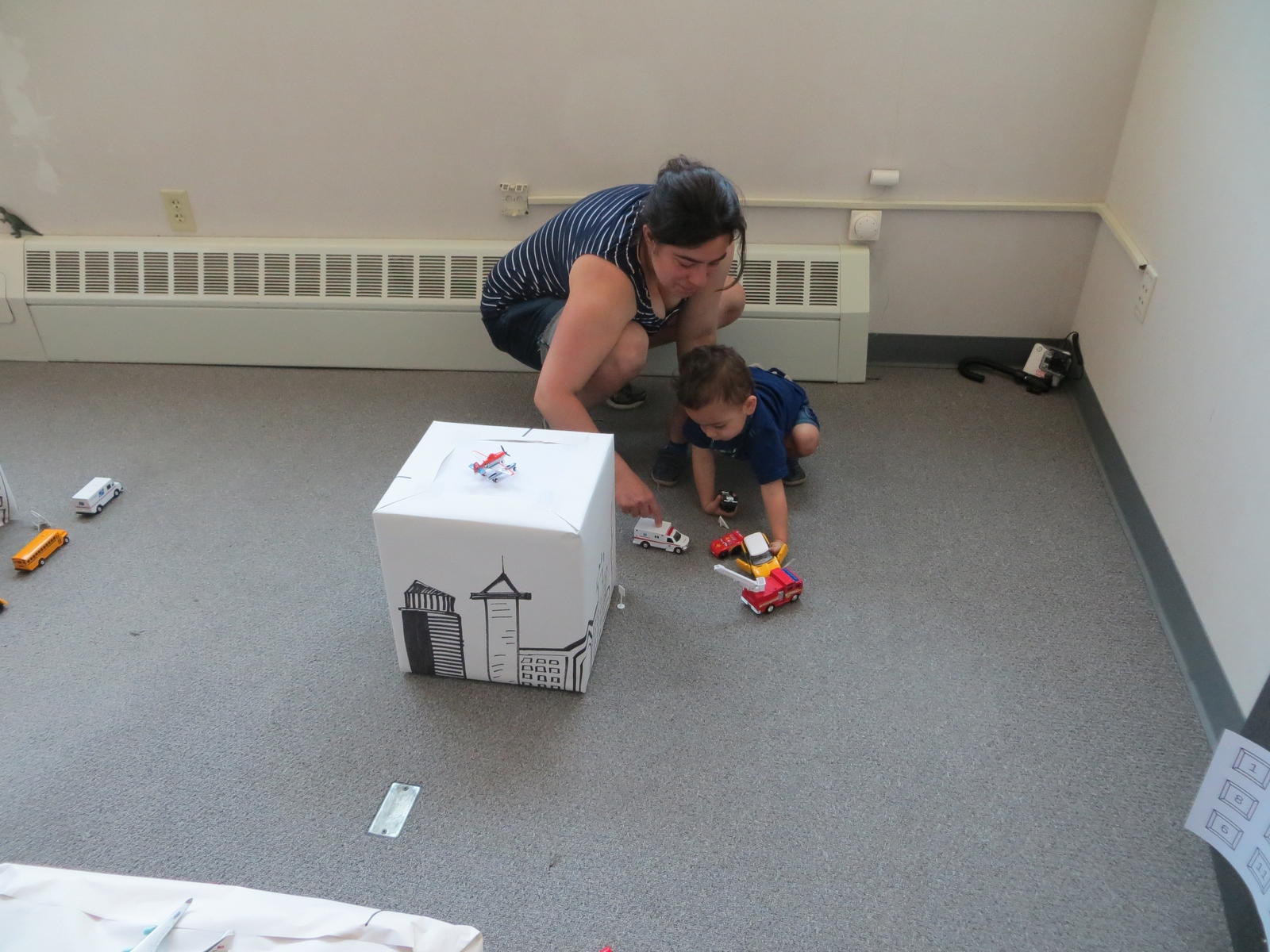
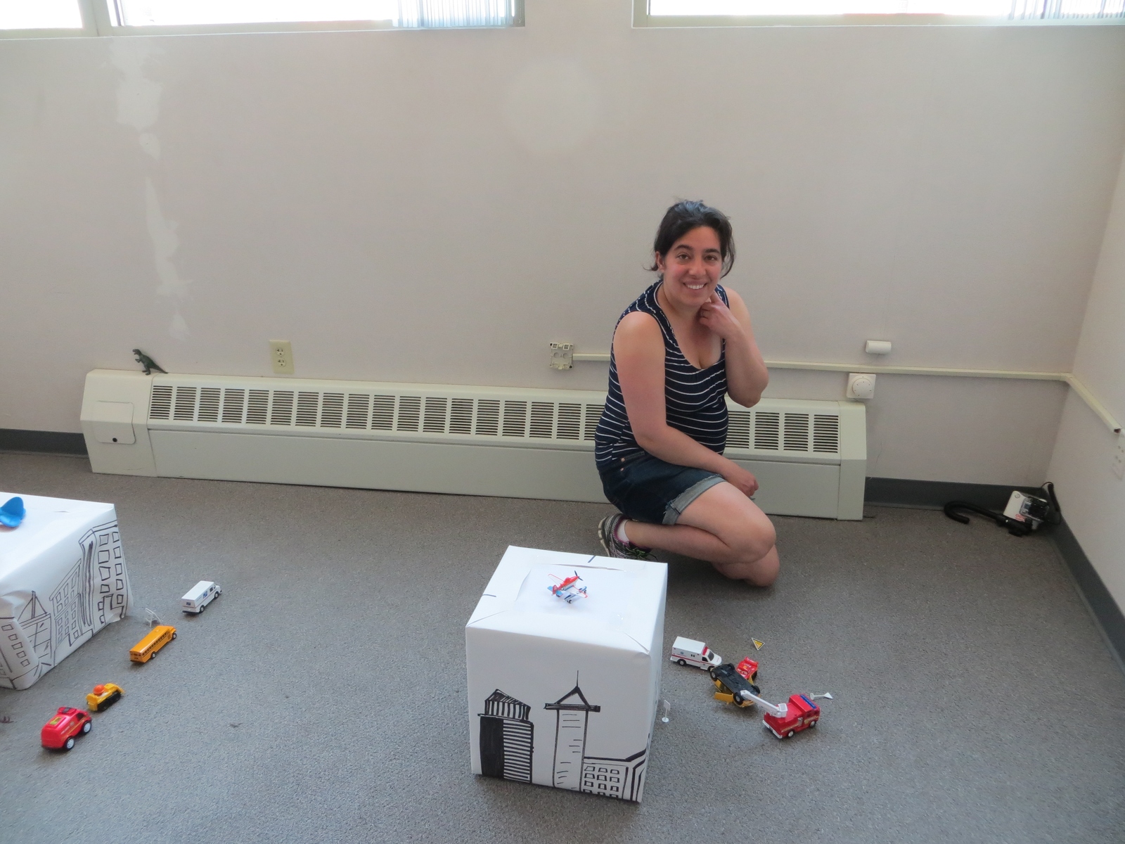
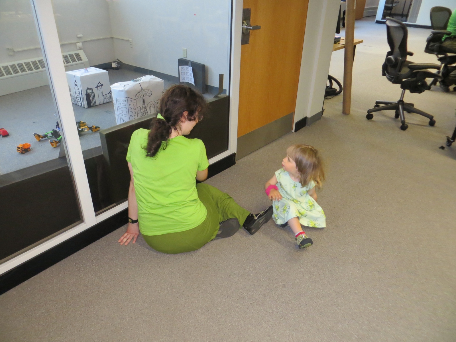
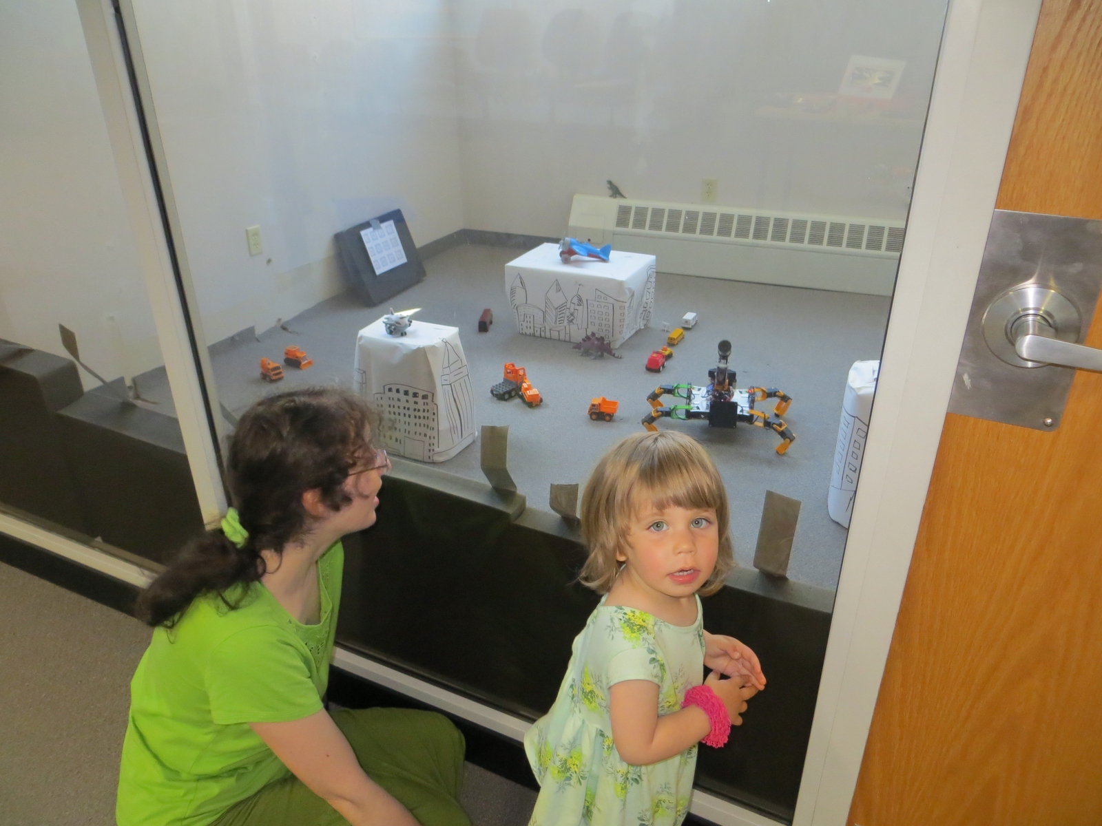
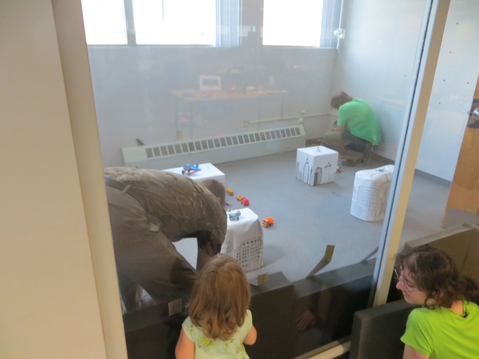
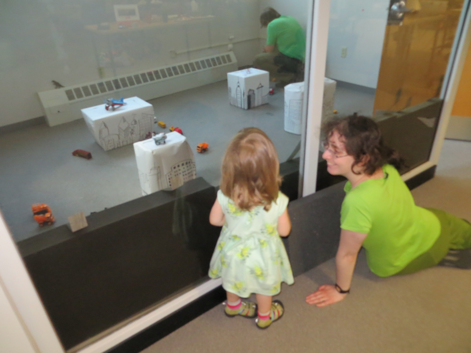
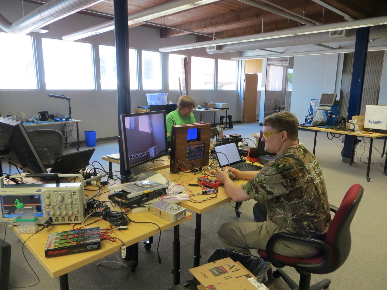
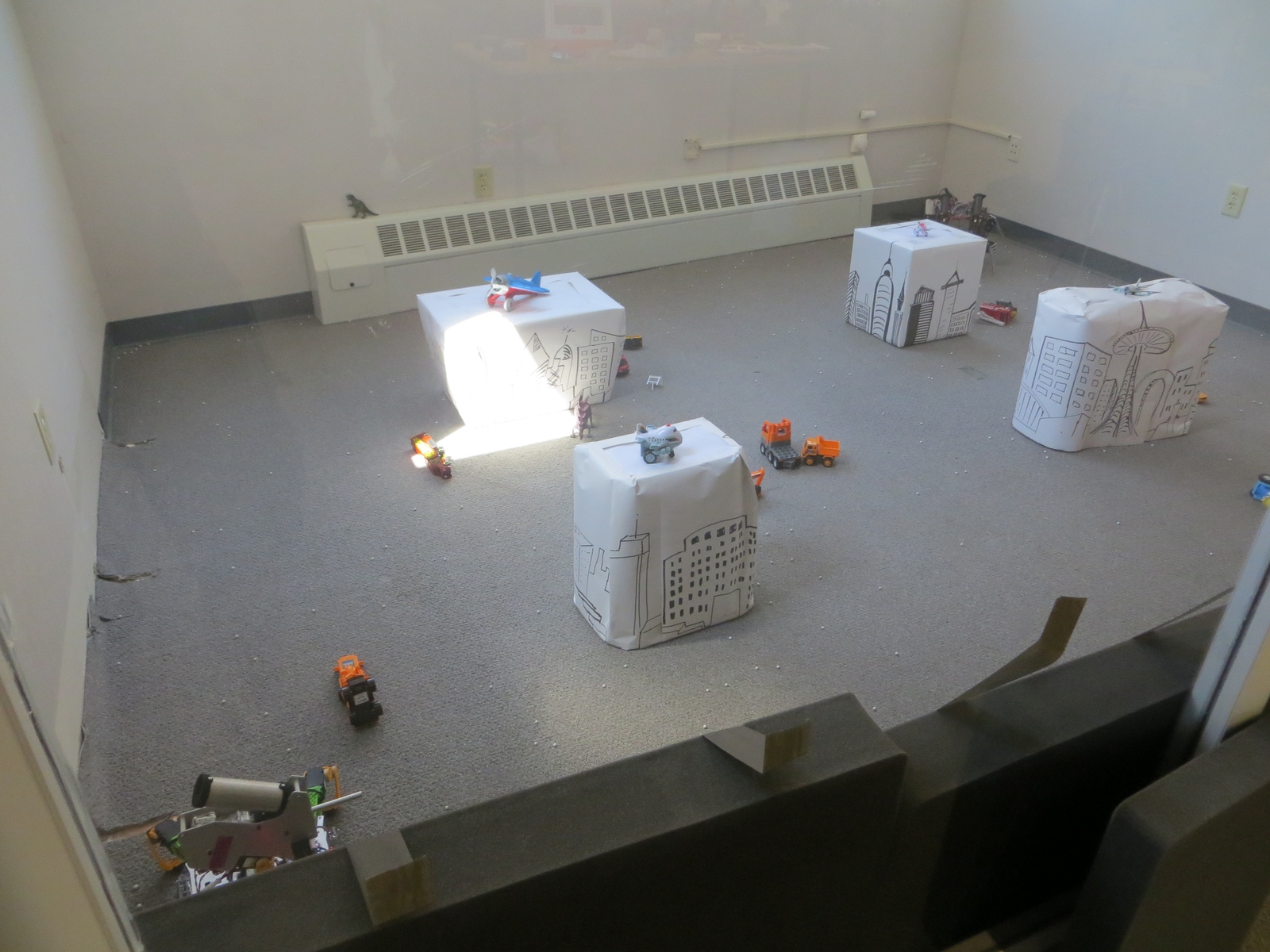
We just concluded the first ever Boston Mech Warfare Expo this weekend, held at Jaybridge Robotics in Cambridge. We had a lot of exciting mech fighting action, learned a lot, and even had a fair amount of exciting repairs! There are many hours of video I need to sort through, but in the meantime, here are some photos:
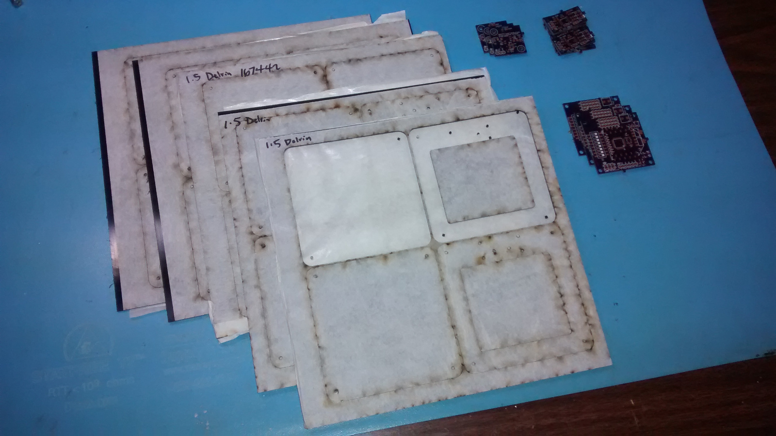
A whole lot of laser cut parts and printed boards just arrived for the scoring system for Super Mega Microbot. We’ll get them put together and tested soon!
In our efforts to reduce weight and complexity for Savage Solder, over the Christmas holiday and first couple of months of 2015 we designed a new computer system based on the Odroid U3 instead of the Mini-ITX form factor PC we had used previously.
Functions
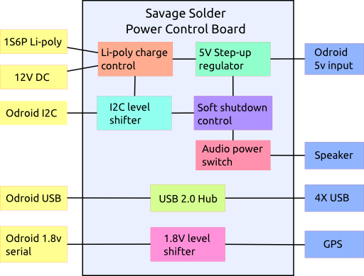
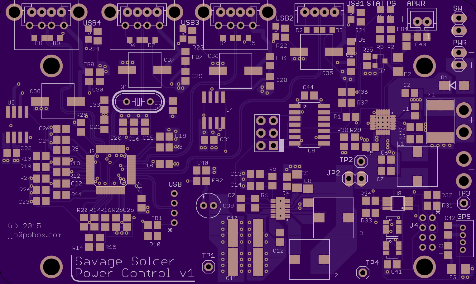
To make that happen, we put together a new power control board which was designed as a “shield” for the Odroid. It has the following functions:
Li-polymer charge management: Previously, Savage Solder used a laptop battery extender, which was functional, but suitable capacities came only in large form factors. We gained a lot of flexibility by using a custom form factor li-poly battery pack, but this means that charge control and safety need to be addressed.
DC/DC step up regulator: The Odroid (and other things), need 5V, so we have a step up regulator to bring the li-poly voltage up to what the Odroid can use.
USB hub: The Odroid has 3 USB ports, (4 if you count the OTG port). We need more than that, and there aren’t many small form factor hubs which would fit into a tiny enclosure. This needed to be USB 2.0 high speed, to support webcams.
Serial level shifter: To reduce the demand for USB ports, we pull out the exposed 1.8V serial port from the Odroid and level shift it up to 5V on a connector that also has 5V power. For Savage Solder, this is used for the GPS.
Speaker power: The control board has a FET to switch the audio power directly from the li-poly pack.
Soft shutdown management: The Odroid’s filesystem could be compromised if it gets powered off unexpectedly. We have a low power microcontroller which reads a discrete switch, informs the Odroid, and powers the system off after the Odroid has had a chance to shutdown cleanly.
**I2C Level shifter:**The Odroid’s expansion port I2C is level shifted to the li-poly voltage level to communicate with the li-poly charger control IC and the shutdown management microcontroller.
Functional block diagram
Components
These were the primary components that the rest of the board was designed around:
Part
Manufacturer
Function
BQ24192
TI
Li-poly charge management
LTC3124
Linear
5V step-up regulator
CY7C65632
Cypress
USB hub
ATTiny841
Atmel
Soft shutdown control
TCA9517
TI
I2C level shifter
SN74LVC1T45
TI
Serial level shifter
PCB
One of our goals with this design was to be pretty sure that the board itself would not be the cause of power problems, signal integrity problems, or really any sort of problems. Thus each USB port’s power is separately switched with a separate large decoupling capacitor and the USB signals have ESD protection. The board itself is 4 layer to give a proper ground plane under each of the USB traces and keep the impedance matched well. All the external connectors with power are separately decoupled and have PTC resettable fuses inline.
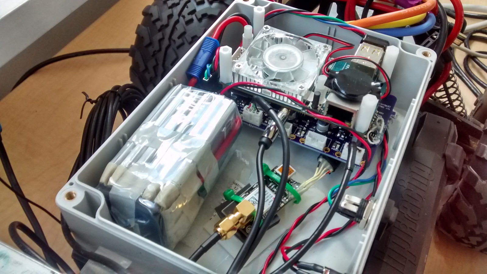
As mentioned, the board was designed as a “shield” for the Odroid. That meant that the mounting holes matched up with Odroid’s, and that the Odroid’s expansion port connects through with a stacking connector. Additionally, the USB connection was made by desoldering the Odroid’s vertical USB connector and using another stacking pin header to connect the two boards.
The board was manufactured on OSHpark’s 4 layer process, which worked out just fine for this project.
oshpark.com rendering
Assembly was challenging, especially for the QFN parts. The one that we built up so far I assembled by hand, using an iron and a hot air rework station with a lot of retries. If we make a subsequent revision, it will need to be with a toaster oven reflow system, or contracted out. Hand assembly time was probably around 16 hours.
While not strictly on the board itself, desoldering the vertical USB connector on the Odroid was very challenging as well. We ruined one Odroid in the process, and the other needed hand rework to replace some components which were lost in the desoldering process.
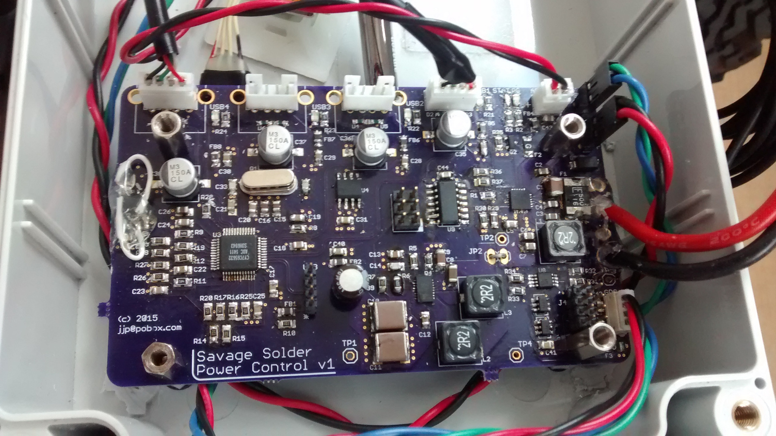
Final assembled board
There are of course a number of errata in the version one board, but nothing that couldn’t be reworked in place.
Installation and test
So far, we haven’t identified any performance or reliability problems when testing on Savage Solder. The board ran through our spring testing and RoboGames Robogamellan run without being the cause of any known failures.
Savage Solder competed in the Robomagellan event in the newly restored and most impressive Robogames 2015 this past weekend. We had two successful runs out of 3, one with no bonus cones and one which touched the challenging 0.01 bonus cone. Both runs put us on the top of the leaderboard.
Other competitors
Here are links to videos I found or uploaded from other other competitors from last weekend:
As part of preparing Savage Solder for events this spring, I’ve been overhauling the computer and sensing platform to have higher reliability and lower weight. One of the changes was a new LCD and input interface.
I wrote up the previous LCD here before, which was the width of the car, pretty heavy, and not resistant to the elements. For this version, I wanted to use a smaller screen, and remove the possibility of moisture getting into the case, while still maintaining roughly the same USB interface.
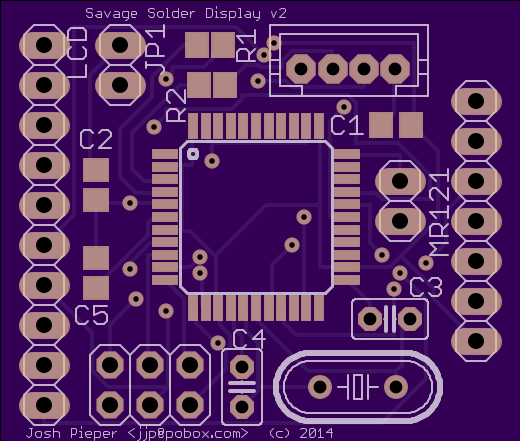
PCB and Assembly
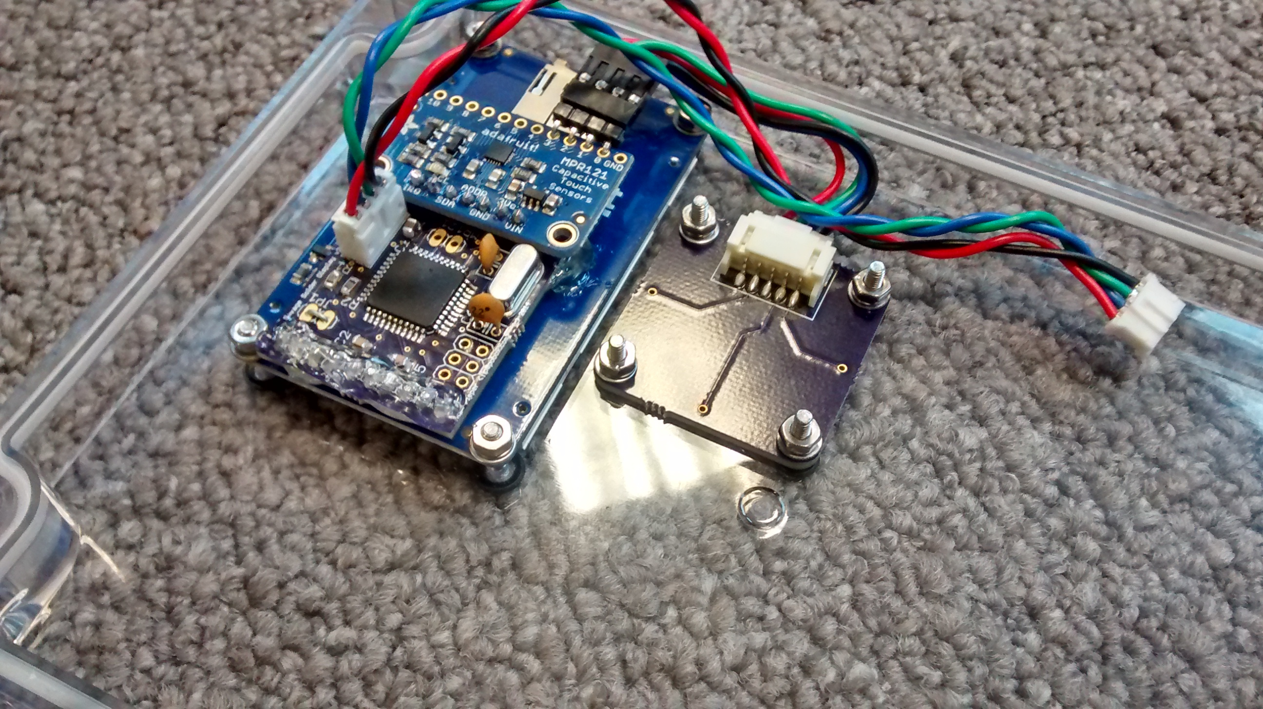
The display I ended up using was the 2.2" TFT LCD from Adafruit. It is color, has sufficient pixels to display everything we wanted, and has a SPI interface. The other half of the solution is the input device, for which I decided to use an off the shelf MPR121 capacitive touch sensor controller, with a breakout board, also from Adafruit.
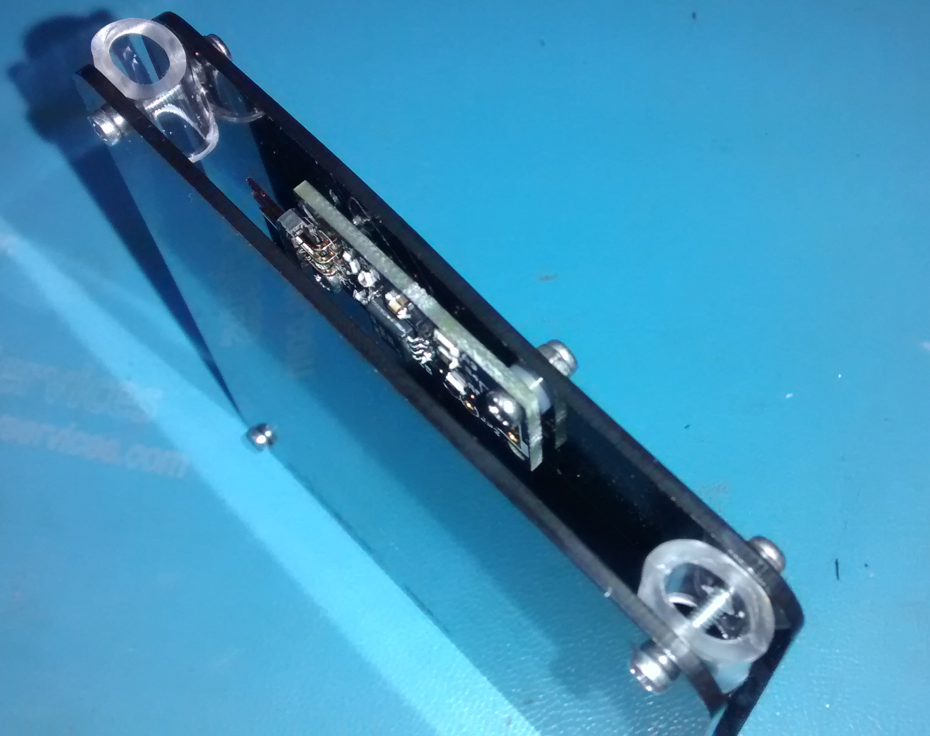
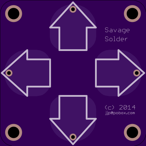
As before, these were glued together with a custom board holding an ATMega32U4 and a few other miscellaneous components. It is mezzanine mounted to the LCD and touch board, and has and external JST connector for USB. Also custom printed was the touch sensor itself. It is nothing more than a PCB with solder-masked copper where each of the touch sensitive areas should be, pulled out to a connector on the back.
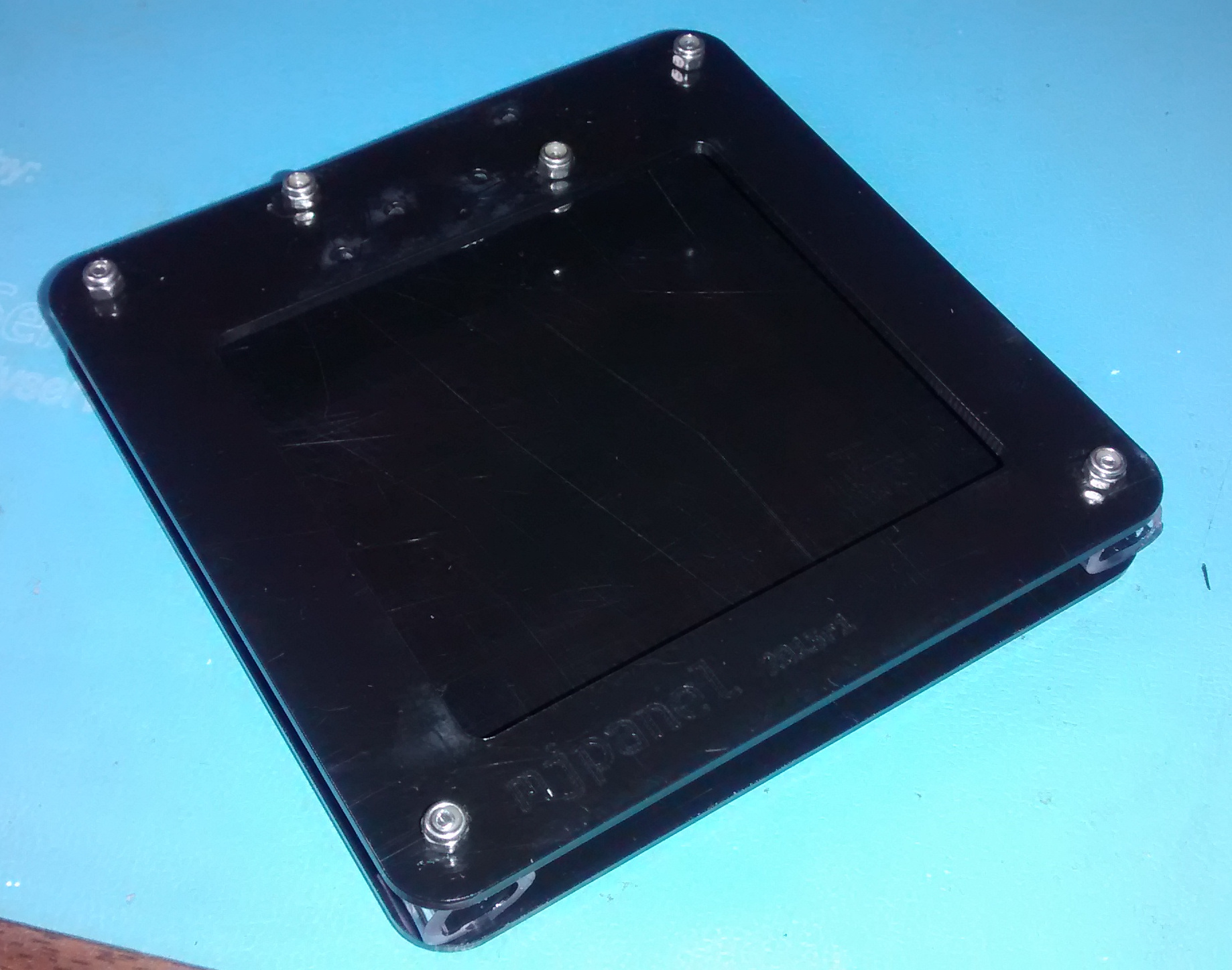
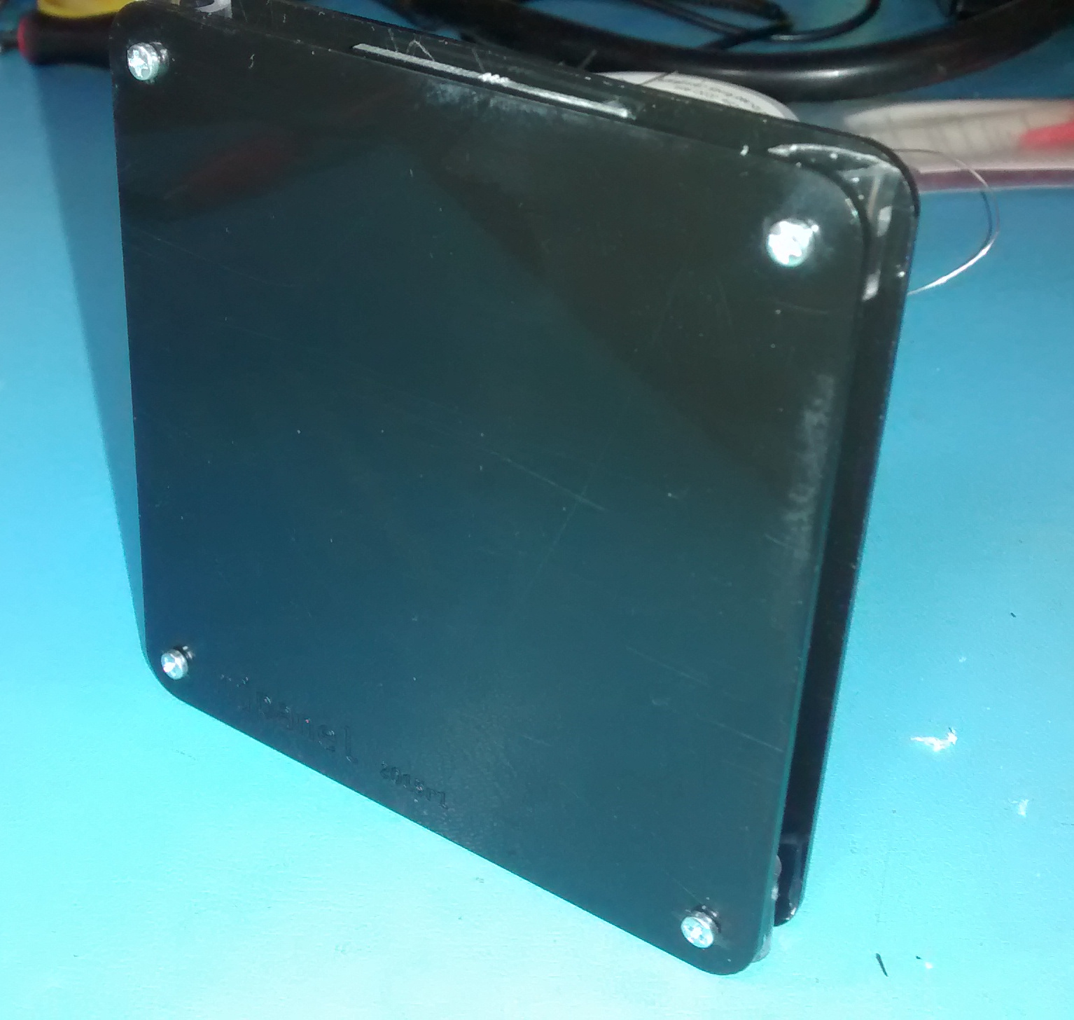
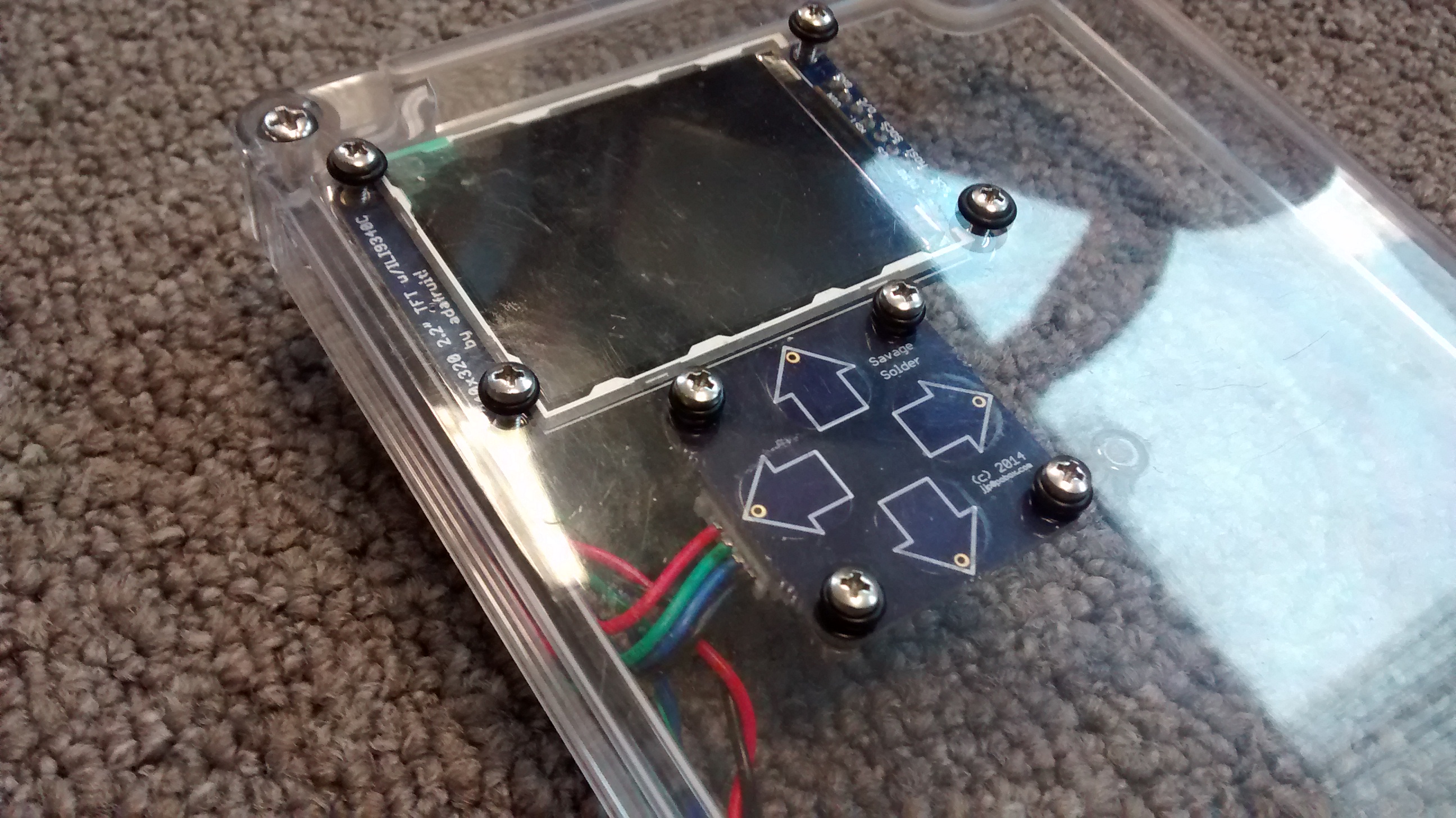
The entire assembly was designed to be mounted to the lid of an off the shelf enclosure with a clear polycarbonate lid (which is where the rest of the electronics is going). The LCD and touch board each have four mounting holes, which are attached with a bolt, nut and lockwasher assembly. Sealing is accomplished with neoprene o-rings on the outer surface of the lid.
Assembled LCD from front
Assembled LCD from back
Software
The MPR121 has a lot of options, many of which influence the performance of the device. The enclosure I am using is an off the shelf one from BUD (PN-1324-C amazon link). It has a polycarbonate lid approximately 1/8" thick, which is kind of at the extreme of what you can get capacitive touch sensors to work through. I was inspired by Adafruit’s MPR121 library, but rewrote it to not require Arduino. I had to tweak a number of the MPR121 constants as well to work under the thick polycarbonate:
MPR121 Register
Adafruit
Savage Solder
CONFIG1
0x10
0x20 (32uA charge current)
Thresholds
12, 6
4, 2
For rendering text on the display, I also based my code on the Adafruit ILI9340 library. Since this LCD controller has to render text one pixel at a time, it was much slower than the HD44780 text-based controller we were using previously. To get remotely acceptable performance, I had to make the AVR keep a framebuffer around, and only re-draw characters which had actually changed.
To act as a forcing function in our development of Super Mega Microbot, we put together a Mech Warfare style qualification video, showing it driving around for more than 5 minutes shooting at some targets. Here it is!
legtool is the library and graphical application I’ve developed for inverse kinematics and gait generation to use with Super Mega Microbot. I’ve pushed a public version of it to github, in the hopes that it may be useful for other developers of legged robots.
I’ve also put together a short demonstration video, showing how to download, install, and use legtool with a gazebo simulated quadruped.
In lieu of actual documentation (or possibly to start generating the text of some), I’ve written some text describing what legtool does and how to to use it below.
legtool overview and installation
legtool is a python library and PySide based graphical application useful for pose generation, inverse kinematics, and gait generation for legged robots. It consists of a set of python libraries, and a graphical debugging application which uses those libraries to allow a developer to explore legged locomotion. It has primarily been tested on Ubuntu linux, but may be portable to other operating systems.
legtool is not yet packaged for installation, so all you need to do is clone the github repository and install the dependencies as documented in the README.
git clone https://github.com/jpieper/legtool.git
Legtool by default creates a configuration file in ~/.config, however, you can specify an alternate configuration on the command line using the -c option. If you have multiple robots, or a simulation and an actual robot, you will want to keep multiple configurations around.
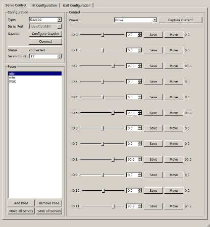
Servo tab
The first tab which is active, the “servo” tab, contains controls to select the servos to control and configure them, along with controls to maintain a list of named poses, where each pose consists of a set of servo positions.
legtool servo tab
Here you can move servos individually to verify their operation, and compose poses. The only use for poses currently is in the later inverse kinematics tabs, so there is no need to define more than idle, minimum, and maximum.
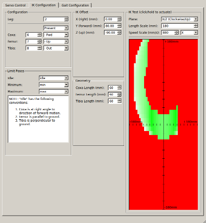
Inverse kinematics tab
The second tab, the IK tab, lets you configure which servos are in which leg, what sign they have, and also the geometry of the legs. The lower right corner visualizes the achievable region of operation in 2D. You can select alternate projections, and change the centerpoint of the test using the IK Offset group. Clicking on the rendering will command that leg to that position.
legtool IK tab
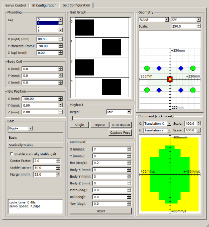
Gait tab
The third, and currently final tab, contains controls to allow configuring the placement of all shoulder joints, marking the center of gravity, and configuring the gait engine. It provides several debugging facilities to allow visualizing the results of the gait engine.
legtool gait tab
The geometry configuration is in the upper left. The shoulder position can be set individually for each leg. The center of gravity and idle position are common to all legs. The gait configuration area in the lower left selects which gait to use, and then exposes a number of configuration options for that gait.
The remainder of the tab is devoted to interactive tools for debugging the gaits:
Gait graph: The gait graph in the upper middle shows for the duration of a single cycle, when each of the legs is in the air.
Geometry view: Visible in the upper right, this shows a 2D rendering of where the shoulders, legs, body, center of gravity, and support polygon are located.
Graphical command view: Visible in the lower right, the graphical command view shows which commands are feasible given the current geometry and gait configuration. Any two command axes can be selected, after which the feasible region is shown in green, regions where the speed is limited are in yellow, and totally infeasible regions are in red.
Playback: The playback scrubber allows you to slide back and forward through a gait cycle, visualizing the results in the geometry view or on the simulated or real robot.
Textual command area: All of the 9 degrees of command freedom are settable here, in addition to the two available in the graphical command view.