ARR: Initial Camera Exploration: Wiring
What I expected to be the hardest hardware portion of the ARR has not disappointed – the camera. To recap, I am in the process of designing and building an autonomous helicopter. As part of that, I wanted to use a vision system combined with a laser pointer to provide low cost altimetry during takeoff and landing. The IGEP COM Module has a dedicated camera port with support for both camera and serial interfaces, and there are a large number of cheap camera phone camera modules out there which should be sufficient. How hard can it be?
I started with a TCM8230MD from SparkFun for which I simultaneously ordered a breakout board from some random online retailer. Unfortunately, the breakout board never came. I tried using some 26 guage wire I had around and a magnifying glass to solder up a by-hand breakout board to no avail. Finally, I broke down and found http://sigalrm.blogspot.com/2011/03/tcm8230md-breakout.html who posted eagle files of a breakout board. I dutifully submitted them to batchpcb and waited.
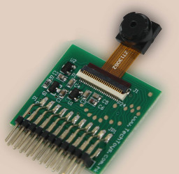
TechToys OV9650 Module
While I was waiting for batchpcb, I simultaneously ordered an OV9650 based board from techtoys, who also sold a breakout (pictured right). While the breakout was on 1mm spacing instead of 0.1in spacing, it was still a lot easier to experiment with. The Hong Kong post has gotten remarkably good, because this development board arrived long before the batchpcb breakout did, so I started integrating it. This board operates at 3.3V, while the TI DM3730 in the IGEP COM Pro uses 1.8V for all of its external IO. To mediate between them for logic level signals, I used a bank of SN74LVC245ANs from digikey, along with 2 discrete N-FETs to shift the I2C bidirectional signals as described in this application note from NXP.
The next challenging step was getting the camera port on the IGEP COM Pro into a usable form. It has a 27 pin 0.3mm FFC style connector, which if you haven’t seen one before is tiny! To make this work, I got a 4 inch passthrough cable from digikey and mating connector, and this 0.3mm FFC breakout from proto-advantage.com. I soldered down the FFC connector to the breakout using my hot air rework station, but should have used an iron with solder-wick technique, as the plastic on the connector melted and bubbled up a bit during soldering. Fortunately, it still worked, so I didn’t need to use my spare.
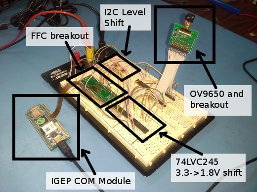
At this point, I had the camera and IGEP COM Module nominally wired up in a way that should be usable. The final breadboard is pictured above. To make progress from here, I wanted to try a smoke test: communicate with the camera over it’s I2C interface to verify that it is powered and working. However, I quickly discovered that it wouldn’t do anything unless it was supplied with a valid clock. This turned into my next odyssey – trying to enable the clock output on the TI DM3730 in the IGEP COM Module. That is involved enough to be the subject of a later post.