
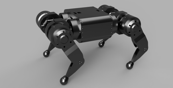
As described in my roadmap, the chassis for the quad A0 was on the verge of failing, or causing the shoulder motors themselves to fail, after only a few hours of walking around. Also, it was nigh impossible to assemble, disassemble, or change anything about it. Thus, the chassis v2!
More than one piece
The old chassis was a single monolithic print that took about 35 hours of print time. Because of its monolithic nature, there were lots of interference problems during assembly. For instance, the shoulder motors could only have 4 of the 6 possible bolts installed, and 2 more of the bolts extended beyond the chassis entirely. I decided to break it up into multiple pieces, which uses a lot more inserts and bolts, but should allow for a feasible order of assembly and manageable repair.
Now there are separate front and back plates, to which the shoulders can be attached in isolation. Then the top plate can attach to that, followed by the side plates, the battery holder, and eventually the bottom plates.
Enclosing the electronics
V1 had the primary computer sitting on top of the chassis. That was a legacy from the first Mech Warfare configuration, where the primary computer sat in the turret. I’ve decided that for Mech Warfare, I’ll just put a second independent computer in the turret, which frees the robot computer to be placed inside the chassis where it is much less likely to get mangled.
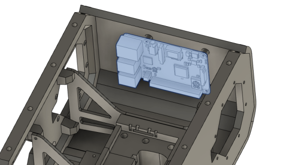
The power distribution board is now mounted to the other side opposite the computer, instead of on the now top-plate.
Power switch and strap
I’ve left room for a recessed top mounted power switch on the top plate. This should remove the need to unplug and re-plug the battery any time that power needs to be cycled. That hole is marked in red below.

Also, while I’m at it, I left holes in the top through which a carrying strap can be threaded (marked in blue above). The old chassis had some M3 inserts that I screwed eye bolts in and then threaded some cord through. That didn’t work terribly well and was unsightly.
Battery
As mentioned in the roadmap, I was going to try and replace the battery with something with a smaller form factor. I looked through a number of batteries, and got a Milwaukee M18 as the best of the options, but ultimately decided that the Ryobi style was the best compromise for now despite the wasted space. All the lower profile ones required insertion sliding in from the side, which would have required that the chassis be much longer than it was already.

Thus, I still have the 3D printed Ryobi battery holder, only now it attaches to the top plate with just some bolts instead of a complicated dovetail arrangement I had previously.

Stiffeners
Since this is being printed in multiple pieces, I wanted a separate piece to increase the longitudinal stiffness. That is now just two plates which bolt to the front and back plate, and to the battery holder.

Next steps
Next up is printing and assembling this chassis!

Question,
You put the raspberry pi on the side panel and the Raspberry pi Hat including Bosch IMU should be on it. Don’t you have any problem if the IMU is located on the side? I guess you need to offset position and pose data from IMU.
LikeLike
Yep. No matter where the imu is located you still need to reference its 3d pose to the body frame.
LikeLike
Hi,
Thanks for sharing your progress. Did you release fusion360 cad files? I would like to get them if you do not mind.
LikeLike
I snapshot the chassis F360 files intermittently into git at: https://github.com/mjbots/moteus/blob/master/hw/chassis_v2/chassis_v2.f3z
LikeLike